EP1338811A1 - Uniaxial hinge device with a plurality of torque generating parts - Google Patents
Uniaxial hinge device with a plurality of torque generating parts Download PDFInfo
- Publication number
- EP1338811A1 EP1338811A1 EP01981035A EP01981035A EP1338811A1 EP 1338811 A1 EP1338811 A1 EP 1338811A1 EP 01981035 A EP01981035 A EP 01981035A EP 01981035 A EP01981035 A EP 01981035A EP 1338811 A1 EP1338811 A1 EP 1338811A1
- Authority
- EP
- European Patent Office
- Prior art keywords
- shaft
- fixed
- cam
- rotary
- torque
- Prior art date
- Legal status (The legal status is an assumption and is not a legal conclusion. Google has not performed a legal analysis and makes no representation as to the accuracy of the status listed.)
- Granted
Links
Images




Classifications
-
- G—PHYSICS
- G06—COMPUTING OR CALCULATING; COUNTING
- G06F—ELECTRIC DIGITAL DATA PROCESSING
- G06F1/00—Details not covered by groups G06F3/00 - G06F13/00 and G06F21/00
- G06F1/16—Constructional details or arrangements
- G06F1/1613—Constructional details or arrangements for portable computers
- G06F1/1633—Constructional details or arrangements of portable computers not specific to the type of enclosures covered by groups G06F1/1615 - G06F1/1626
- G06F1/1675—Miscellaneous details related to the relative movement between the different enclosures or enclosure parts
- G06F1/1681—Details related solely to hinges
-
- G—PHYSICS
- G06—COMPUTING OR CALCULATING; COUNTING
- G06F—ELECTRIC DIGITAL DATA PROCESSING
- G06F1/00—Details not covered by groups G06F3/00 - G06F13/00 and G06F21/00
- G06F1/16—Constructional details or arrangements
- G06F1/1613—Constructional details or arrangements for portable computers
- G06F1/1615—Constructional details or arrangements for portable computers with several enclosures having relative motions, each enclosure supporting at least one I/O or computing function
- G06F1/1616—Constructional details or arrangements for portable computers with several enclosures having relative motions, each enclosure supporting at least one I/O or computing function with folding flat displays, e.g. laptop computers or notebooks having a clamshell configuration, with body parts pivoting to an open position around an axis parallel to the plane they define in closed position
-
- G—PHYSICS
- G06—COMPUTING OR CALCULATING; COUNTING
- G06F—ELECTRIC DIGITAL DATA PROCESSING
- G06F1/00—Details not covered by groups G06F3/00 - G06F13/00 and G06F21/00
- G06F1/16—Constructional details or arrangements
- G06F1/1613—Constructional details or arrangements for portable computers
- G06F1/1633—Constructional details or arrangements of portable computers not specific to the type of enclosures covered by groups G06F1/1615 - G06F1/1626
- G06F1/1675—Miscellaneous details related to the relative movement between the different enclosures or enclosure parts
- G06F1/1679—Miscellaneous details related to the relative movement between the different enclosures or enclosure parts for locking or maintaining the movable parts of the enclosure in a fixed position, e.g. latching mechanism at the edge of the display in a laptop or for the screen protective cover of a PDA
-
- E—FIXED CONSTRUCTIONS
- E05—LOCKS; KEYS; WINDOW OR DOOR FITTINGS; SAFES
- E05D—HINGES OR SUSPENSION DEVICES FOR DOORS, WINDOWS OR WINGS
- E05D11/00—Additional features or accessories of hinges
- E05D11/10—Devices for preventing movement between relatively-movable hinge parts
- E05D11/1028—Devices for preventing movement between relatively-movable hinge parts for maintaining the hinge in two or more positions, e.g. intermediate or fully open
- E05D11/1078—Devices for preventing movement between relatively-movable hinge parts for maintaining the hinge in two or more positions, e.g. intermediate or fully open the maintaining means acting parallel to the pivot
-
- E—FIXED CONSTRUCTIONS
- E05—LOCKS; KEYS; WINDOW OR DOOR FITTINGS; SAFES
- E05Y—INDEXING SCHEME ASSOCIATED WITH SUBCLASSES E05D AND E05F, RELATING TO CONSTRUCTION ELEMENTS, ELECTRIC CONTROL, POWER SUPPLY, POWER SIGNAL OR TRANSMISSION, USER INTERFACES, MOUNTING OR COUPLING, DETAILS, ACCESSORIES, AUXILIARY OPERATIONS NOT OTHERWISE PROVIDED FOR, APPLICATION THEREOF
- E05Y2999/00—Subject-matter not otherwise provided for in this subclass
Definitions
- the present invention relates to a single-shaft hinge component employed in the folding section of small electronic devices such as cellular phones, notebook computers, personal digital assistants or DVD monitors.
- the problem that the invention is intended to solve is to provide a single-shaft hinge component of high durability capable of being made of small size and light weight in cellular phones or notebook computers for which smaller size and lighter weight are required.
- the present invention are as follows:
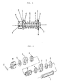
- Figure 1 is a front view of an embodiment of the invention according to claim 1 and Figure 2 is an exploded perspective view of Figure 1.
- a retaining flange is formed at the right-hand end of a shaft 1 and near the left-hand end thereof there is provided a pin hole into which is inserted a spring pin 7 for fixing purposes.
- a joining member 6 is fitted at the left-hand end of the shaft, this joining member 6 being fixed to the shaft 1 by this insertion of the spring pin 7 through the pin hole.
- the external circumferential shape of the shaft 1 is oval-shaped, with part thereof being cut parallel with the axis.
- the cross-sectional shape of the shaft 1 employed in the present invention is oval-shaped
- the cross-sectional shape could be rectangular or elliptical or of other shape and an E ring or caulking or other similar means could be employed instead of the flange or pin retaining element for fixing of the ends.
- resin molding, die casting, cutting or cold pressing or other similar techniques could be adopted; as the material thereof, a suitable choice may be made in accordance with the hinge performance from resin, metal or other material.
- 2 is a resin spacer of excellent lubricating properties
- 3 is a rotary cam with concave sections provided in one face thereof and another face thereof being planar, provided with a hole in the middle thereof allowing the shaft to be inserted therethrough in rotatable fashion
- 4 is a fixed cam having convex sections on one face thereof and another face thereof being planar, having the shaft 1 passing therethrough and being fitted onto the oval-shaped external circumference of the shaft cross-section, being slidable along the shaft and rotating together with the shaft
- 5 is a coil spring constituting an elastic member that generates rotary frictional torque by applying pressure-contacting force to the rotary and fixed cams
- 6 is a joining member
- 7 is a spring pin for fixing the joining member 6 to the shaft 1
- 8 is a stop plate.
- the joining member 6 is fixed to the shaft 1 by means of the spring pin 7 and a concave/convex section comprising a mechanism for preventing rotation with respect to a pivotally attached component is provided at the circumference of the flange 6.
- the hinge device according to this embodiment, as shown in Figure 2 is therefore completed by driving the spring pin 7 into the hole provided in the flange 6 and shaft 1 as the final assembly step.
- FIG. 1 shows the condition in which this rotary cam 3, which has concave sections, and the fixed cam 4, which has convex sections, are arranged to generate rotary frictional torque by pressure contact force being applied thereto by the coil spring 5.
- the positions in which the rotary cam 3 and the fixed cam 4 are assembled could be interchanged. If this is done, the coil spring 5 is arranged to press against the face opposite the abutment face of the rotary cam.
- a material is selected having excellent resistance to friction, such as metal, resin or ceramic.
- Figure 1 shows the mechanism in a condition in which the concave sections and convex sections of the rotary cam 3 and fixed cam 4 are in coincidence and the coil spring 5 is in an engaged (click) relationship; this engaged condition occurs every time rotation takes place through an angle of 180°.
- the engaged condition is eliminated and a shift takes place to a condition in which a fixed rotary frictional torque is generated with the convex sections of the fixed cam 4 and the flat sliding face of the rotary cam 3 in a condition of pressure contact.
- a so-called "free stop” condition is realized in which the angle of the inclination of the cover produced by shaft rotation by opening/closing of the cover containing the monitor can be stopped at any desired angle.
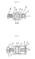
- Figure 3 is a front view of another embodiment of the invention according to claim 1.
- Rotary cams 3 are connected by means of a joining sleeve 9 shown in Figure 4 having an internal diameter that is substantially the same as the outer diameter of the rotary cams 3 and components such as the cams could also be enclosed within the sleeve. Thanks to the use of the joining sleeve 9, attachment of the main body onto the component that it co-operates with is simplified and ingress of foreign bodies can be prevented.
- Figure 5 is a front view of an embodiment of the invention according to claim 2, consisting of a single-shaft hinge device having a construction in which a plurality (two in the case of Figure 5) of assemblies constituted by fixed cams 4, arranged at both ends of each coil spring 5, and rotary cams 3, coupled with the respective fixed cams 4, are set in position with a single shaft 1 passing therethrough. Pressure contacting force is applied to adjacent rotary cams 3 by abutment faces 3-8 of the fixed cams 4, so that rotary frictional torque is generated by relative rotation thereof. It should be noted that the positions of the rotary cams 3 and fixed cams 4 in the assemblies could be reversed.
- Figure 6 is a front view of an embodiment of the invention according to claim 3.
- Two rotary cams 3 are assembled with two fixed cams 4 with abutment faces 3-8 arranged to be in contact therewith, with pressure contacting force applied by coil springs 5 from both ends of a single shaft 1 passing therethrough.
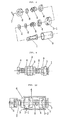
- Figure 7 is a front view of another embodiment of the invention according to claim 3.
- Figure 8 is an exploded perspective view of Figure 7.
- 3-1 is a rotary cam having concave faces on both side faces of the disc and formed with a hole through which is passed a shaft 1 in rotatable fashion;
- 9 is a joining sleeve having an internal diameter such as to fit and surround the outer circumference of the rotary cam 3-1 and that engages a retaining flange provided at the right-hand end of the shaft 1.
- Figure 9 is a front view of an embodiment of the invention in which the inventions of claim 2 and claim 3 are combined on the axis of shaft 1 wherein a further combination of a fixed cam 4 and a rotary cam 3 is set in position at the right-hand end of the coil spring 5 on the right of the embodiment of Figure 6.
- FIG. 10 is a front view of yet a further embodiment of invention in which the inventions according to claim 2 and claim 3 are combined on the axis of the shaft 1.
- Sections for torque generation at two locations are formed by abutment of fixed cams 4 having convex sections at two locations with both sides of a rotary cam 3-1 having concave sections at two locations on both side faces;
- a further torque-generating section is formed by coupling a fixed cam 4 having convex sections with a rotary cam 3-2 having concave sections at two locations on its left side face, its right side face being flat at the right-hand end of the coil spring 5 on the right-hand side, thereby making a total of three torque-generating sections in all on the single shaft 1; and a joining sleeve 9 surrounding the outer circumferences of the rotary cam 3-1 and rotary cam 3-2 is provided.
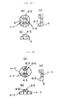
- Figure 11 shows an embodiment of the invention according to claim 5, (a) being a plan view, front view and right-hand side view of a fixed cam 4; elevation of the convex sections 4-2 commences at an angle ⁇ 1 and the peak is at an angle ⁇ 2 .
- the flat sections are 4-5.
- the face on the opposite side is a planar face 4-3, constituting a contacting face with the coil spring 5 (see Figure 1 to Figure 10).
- Figure 11(b) shows a plan view, front view and right-hand side view of the rotary cam 3 facing this fixed cam.
- Figure 12 shows another embodiment of the invention according to claim 5 wherein the convex sections 4-2 of the fixed cam 4 are of rounded shape.
- Figure 12(b) shows the rotary cam 3 facing this fixed cam.
- Figure 13 shows yet another embodiment of the invention according to claim 5 wherein lubrication between the rotary cam 3 and the fixed cam 4 in pressure contact with each other can be stabilized by providing holes 4-4 that accumulate lubricant such as grease.
- Figure 14 shows yet another embodiment of the invention according to claim 5 wherein mutual lubrication of the cams is stabilized by providing holes 4-4 that accumulate a lubricant such as grease in the fixed cam 4 and providing projecting sections 4-6 in the outer circumference of the fixed cam 4.
- a lubricant such as grease
- Figure 15 is a perspective view showing an embodiment of the invention according to claim 6 wherein a round hole 3-6 is provided in the center of a rotary cam 3, a semi-cylindrical convex section 3-7 is formed at the circumference thereof, an oval hole is provided at the center of the fixed cam 4, and a semi-circular annular concave section 4-7 is formed at the circumference thereof.
- the annular concave section 4-7 is fit into the cylindrical convex section 3-7 to form slidable abutment faces. It should be noted that, in the reverse arrangement to that described above, it would be possible to form a semi-circular annular concave section on the rotary cam 3 and to form a semi-cylindrical convex section on the fixed cam.
- Figure 16 is a perspective view showing another embodiment of the invention according to claim 6 wherein portions that are identical with those of Figure 15 are given the same reference symbols and a limited-rotation region is provided in the range 360° - ( ⁇ 7 + ⁇ 8 ) of the rotary cam 3 by forming a projection 3-9 of angular width ⁇ 8 on the outer circumference of the rotary cam 3 and forming a projection 4-8 of angular width ⁇ 7 on the outer circumference of the fixed cam 4.
- Figure 17 is a perspective view of yet another embodiment of the invention according to claim 6 wherein portions that are identical with those of Figure 15 are given the same reference symbols and wherein both sides of the outer circumference of the rotary cam 3 are cut in parallel shape. If the dimension between the cut faces of the rotary cam 3 is taken as L1 and the external diameter of the fixed cam 4 is taken as L2, it is necessary that L1 > L2.
- Figure 18 is a perspective view of yet another embodiment of the invention according to claim 6 wherein portions that are identical with those of Figure 17 are given the same reference symbols and wherein conical convex sections 3-10 are provided on the rotary cam 3.
- Figure 19 and Figure 20 are perspective views of an embodiment of the invention according to claim 7.
- diametrically concave sections 3-3 or concave sections 4-1 are formed on both side faces of the rotary cam 3 or fixed cam 4.
- diametrically opposite convex sections 3-4 or convex sections 4-2 are formed on both faces of a rotary cam 3 or fixed cam 4.
- Figure 21 is a front view of an embodiment of the invention according to claim 8 and Figure 22 is a front view of another embodiment of the invention according to claim 8. Portions that are identical with those of Figure 7 or Figure 10 are given the same reference symbols.
- the pivotally attached component such as the folding section of an electronic device can be held in position by an effect like a click stop function thereon at a prescribed angle by separately fixing the brackets 10 and 11 to the pivotally attached component.
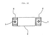
- FIG 23 shows an embodiment of the invention according to claim 9.
- the interior of the joining sleeve 9 is not shown but its construction is identical with the interior of the joining sleeve of Figure 3.
- Joining members 6 are fixed by spring pins 7 at both ends of the shaft.
- the external peripheral sections of the joining member 6 are respectively fitted on by an insertion process onto the pivotally attached component such as the folding section of an electronic device, not shown.
- a high rotary sliding torque can be obtained by means of an elastic member of weak restoring force according to the invention set forth in any of claims 1 to 9.
- the number of components can be reduced and costs lowered by using both side faces of one rotary cam or fixed cam as abutment faces.
- a click action is generated whereby force is generated that provides pulling in to a prescribed angle within a prescribed angular range or that generates a constant torque in a flat section.
- the shaft can be stopped at any desired angle.
- the shaft can be stopped at any desired angle and adhesion with the elastic body is stabilized by making the other face of the rotary cam or fixed cam planar, so a stable energizing force of the elastic member can be obtained without producing irregular loading, no matter what the angle of rotation.
- a pivotally attached component can be held at any desired angle of rotation by means of a joining plate.
- arrangement can be achieved substantially in the middle part of the rotary shaft and a stable action ensured by fixing flanges at both ends.
Landscapes
- Engineering & Computer Science (AREA)
- Computer Hardware Design (AREA)
- Theoretical Computer Science (AREA)
- Physics & Mathematics (AREA)
- Human Computer Interaction (AREA)
- General Engineering & Computer Science (AREA)
- General Physics & Mathematics (AREA)
- Mathematical Physics (AREA)
- Pivots And Pivotal Connections (AREA)
Abstract
Description
Claims (9)
- A single-shaft hinge device comprising a plurality of torque-generating sections and having a single-shaft hinge, the single-shaft hinge comprising a single shaft, rotary cams fitted on this shaft and that are capable of axially moving on the shaft and capable of rotating with respect to the shaft about an axis of the shaft, fixed cams fitted on the shaft and that are capable of axially moving on the shaft but incapable of relative rotation with respect to the shaft, and elastic members arranged coaxially with the shaft and that abut side faces of each adjacent rotary cam and fixed cam against each other, wherein abutment faces of the rotary cams and fixed cams are provided at two or more locations on the single shaft.
- The single-shaft hinge device comprising a plurality of torque-generating sections according to claim 1, wherein a plurality of the rotary cams and fixed cams are arranged coaxially with the shaft so as to abut both ends of the elastic members.
- The single-shaft hinge device comprising a plurality of torque-generating sections according to claim 1, wherein a plurality of the rotary cams and fixed cams are coaxially arranged on the shaft such that one end of each elastic member abuts a face opposite to the abutment face of the rotary cam or the fixed cam.
- The single-shaft hinge device comprising a plurality of torque-generating sections according to claim 1, wherein the inventions according to claims 2 and 3 are combined and arrangement is coaxially made on the shaft.
- The single-shaft hinge device comprising a plurality of torque-generating sections according to any of claim 1 to claim 4, wherein there are provided concave/convex sections and flat sections on the abutment faces of the rotary cam and the fixed cam for causing the torque to change in accordance with an angle of rotation.
- The single-shaft hinge device comprising a plurality of torque-generating sections according to any of claim 1 to claim 4, wherein a flat face is formed on either one of the rotary cam or the fixed cam or on mutual abutment faces thereof for generating a constant torque irrespective of angle of rotation.
- The single-shaft hinge device comprising a plurality of torque-generating sections according to any of claims 1 to 6, wherein an abutment face is formed on one side face or both side faces of the rotary cam or the fixed cam.
- The single-shaft hinge device comprising a plurality of torque-generating sections according to any of claim 1 to claim 7, which further comprises a bracket fixed to one of the rotary cam or the fixed cam and/or shaft and another bracket fixed to one of the fixed cam and/or shaft or the rotary cam, the one bracket and the other bracket being respectively fixed to a pivotally attached component.
- The single-shaft hinge device comprising a plurality of torque-generating sections according to any of claims 1 to 7, wherein a joining member is engaged with a co-operating pivotally attached component at both ends of the shaft.
Applications Claiming Priority (5)
| Application Number | Priority Date | Filing Date | Title |
|---|---|---|---|
| JP2000343600 | 2000-11-10 | ||
| JP2000343600 | 2000-11-10 | ||
| JP2001320317A JP4079407B2 (en) | 2000-11-10 | 2001-10-18 | Uniaxial hinge device having a plurality of torque generating parts |
| JP2001320317 | 2001-10-18 | ||
| PCT/JP2001/009793 WO2002038970A1 (en) | 2000-11-10 | 2001-11-08 | Uniaxial hinge device with a plurality of torque generating parts |
Publications (3)
| Publication Number | Publication Date |
|---|---|
| EP1338811A1 true EP1338811A1 (en) | 2003-08-27 |
| EP1338811A4 EP1338811A4 (en) | 2004-09-01 |
| EP1338811B1 EP1338811B1 (en) | 2006-03-29 |
Family
ID=26603755
Family Applications (1)
| Application Number | Title | Priority Date | Filing Date |
|---|---|---|---|
| EP01981035A Expired - Lifetime EP1338811B1 (en) | 2000-11-10 | 2001-11-08 | Uniaxial hinge device with a plurality of torque generating parts |
Country Status (7)
| Country | Link |
|---|---|
| US (1) | US6948217B2 (en) |
| EP (1) | EP1338811B1 (en) |
| JP (1) | JP4079407B2 (en) |
| CN (1) | CN1208558C (en) |
| AU (1) | AU2002212735A1 (en) |
| DE (1) | DE60118420T2 (en) |
| WO (1) | WO2002038970A1 (en) |
Cited By (1)
| Publication number | Priority date | Publication date | Assignee | Title |
|---|---|---|---|---|
| EP1679443A4 (en) * | 2003-10-28 | 2007-07-18 | Mitsubishi Steel Mfg | HINGE MECHANISM |
Families Citing this family (53)
| Publication number | Priority date | Publication date | Assignee | Title |
|---|---|---|---|---|
| JPH10115570A (en) * | 1996-10-11 | 1998-05-06 | Teisan Kk | Inspection apparatus for leak of a plurality of gas containers |
| JP4150615B2 (en) * | 2003-03-10 | 2008-09-17 | 京セラ株式会社 | Hinge device |
| TW566817U (en) * | 2003-03-11 | 2003-12-11 | Benq Corp | Electronic device and hinge assembly thereof |
| KR100538626B1 (en) * | 2003-05-13 | 2005-12-22 | 주식회사 팬택앤큐리텔 | Hinge apparatus of mobile terminal with deceleration section |
| JP4079833B2 (en) * | 2003-06-03 | 2008-04-23 | 三菱製鋼株式会社 | 2-axis hinge with rotation restriction mechanism |
| TWM243535U (en) * | 2003-06-06 | 2004-09-11 | Hon Hai Prec Ind Co Ltd | Hinge assembly |
| US7274564B2 (en) * | 2003-06-23 | 2007-09-25 | Jaco, Inc. | Locking cradle for tablet computers |
| JP4113092B2 (en) * | 2003-10-24 | 2008-07-02 | 三菱製鋼株式会社 | Biaxial hinge rotation mechanism and mobile phone equipped with the same |
| US7013532B2 (en) * | 2003-10-31 | 2006-03-21 | Shin Zu Shing Co., Ltd. | Hinge |
| KR100735974B1 (en) * | 2003-11-05 | 2007-07-06 | 엘지전자 주식회사 | Hinge structure for door of Kimchi refrigerator |
| JP4306436B2 (en) | 2003-12-11 | 2009-08-05 | 三菱製鋼株式会社 | 2-axis hinge mechanism for harness wiring |
| CN100373290C (en) * | 2004-04-13 | 2008-03-05 | 纬创资通股份有限公司 | Electronic device and rotating structure |
| US6986188B2 (en) * | 2004-06-14 | 2006-01-17 | Shin Zu Shing Co., Ltd. | Hinge |
| US7082642B2 (en) * | 2004-06-18 | 2006-08-01 | Sinher Technology Inc. | Hinge for anchoring and folding on a small pintle |
| US7565719B2 (en) * | 2004-06-18 | 2009-07-28 | Sinher Technology Inc. | Hinge for anchoring and folding on a small pintle |
| CN100439825C (en) * | 2004-09-20 | 2008-12-03 | 乐金电子(天津)电器有限公司 | Hinge structure of refrigerator door for storing pickles |
| CN2777915Y (en) * | 2004-12-30 | 2006-05-03 | 鸿富锦精密工业(深圳)有限公司 | Hinge structure |
| US7222396B2 (en) * | 2005-03-09 | 2007-05-29 | Shin Zu Shing Co., Ltd | Robust hinge |
| JP2006258116A (en) * | 2005-03-15 | 2006-09-28 | Matsushita Electric Ind Co Ltd | Switchgear |
| WO2007007817A1 (en) * | 2005-07-08 | 2007-01-18 | Citizen Holdings Co., Ltd. | Hinge device |
| JP4440189B2 (en) * | 2005-09-01 | 2010-03-24 | 三菱製鋼株式会社 | Biaxial hinge device |
| JP2007094249A (en) * | 2005-09-30 | 2007-04-12 | Roland Corp | Pedal device for musical instruments |
| US20070094845A1 (en) * | 2005-11-01 | 2007-05-03 | Chechu Tech. Enterprise Co., Ltd. | [hinge] |
| CN1959135B (en) * | 2005-11-04 | 2011-06-29 | 深圳富泰宏精密工业有限公司 | Hinge structure, and folding electronic equipment of using the hinge structure |
| US20070234514A1 (en) * | 2006-04-05 | 2007-10-11 | Shin Zu Shing Co., Ltd. | Hinge with a multi-stage positioning function |
| JP4384142B2 (en) * | 2006-07-13 | 2009-12-16 | 日本航空電子工業株式会社 | HINGE DEVICE AND ELECTRONIC DEVICE HAVING THE HINGE DEVICE |
| US20080141492A1 (en) * | 2006-12-18 | 2008-06-19 | Shin Zu Shing Co., Ltd. | Hinge capable of providing different friction forces |
| CN101338783B (en) * | 2007-07-04 | 2011-03-30 | 深圳富泰宏精密工业有限公司 | Hinge structure and portable electronic device using the hinge structure |
| US7631397B2 (en) * | 2007-09-06 | 2009-12-15 | Cheng Uei Precision Industry Co., Ltd. | Hinge |
| US7836550B2 (en) * | 2007-12-27 | 2010-11-23 | Cheng Uei Precision Industry Co., Ltd. | Damping hinge device |
| JP5112121B2 (en) * | 2008-03-13 | 2013-01-09 | 加藤電機株式会社 | Biaxial hinge device and electronic equipment |
| CN101672324B (en) * | 2008-09-12 | 2012-09-19 | 深圳富泰宏精密工业有限公司 | Hinge structure and portable electronic device applying same |
| US20100077565A1 (en) * | 2008-10-01 | 2010-04-01 | Wei-Kuo Huang | Hinge capable of being positioned at any angle |
| US20100175501A1 (en) * | 2009-01-13 | 2010-07-15 | Chao-Chi Lin | Effort-Saving Cam Device of Hinge Assembly for Electronic Device |
| FR2940986B1 (en) * | 2009-01-15 | 2011-01-07 | Saint Gobain Pont A Mousson | JOINT ASSEMBLY AND CORRESPONDING ROAD DEVICE |
| JP5307637B2 (en) * | 2009-06-11 | 2013-10-02 | 株式会社パイオラックス | Hinge device |
| CN102654236B (en) * | 2011-03-01 | 2014-01-01 | 信锦企业股份有限公司 | Support frame and latch unit |
| KR101804576B1 (en) * | 2011-04-26 | 2017-12-04 | 삼성전자주식회사 | Hinge device for portable terminal |
| KR101856780B1 (en) * | 2011-07-13 | 2018-05-10 | 삼성전자주식회사 | Gear cam mounting device in dual-hinge unit of portable terminal |
| KR101969588B1 (en) * | 2012-06-20 | 2019-04-16 | 엘지전자 주식회사 | A rerigerator including an ice container |
| US9101086B2 (en) | 2013-01-15 | 2015-08-04 | Blackberry Limited | Access panels for electronic devices |
| US10267075B2 (en) * | 2017-05-01 | 2019-04-23 | Nio Usa, Inc. | Self-contained door hinge mechanism |
| DE112018006003T5 (en) * | 2017-11-24 | 2020-08-13 | Sugatsune Kogyo Co., Ltd. | hinge |
| DE102018109569B4 (en) * | 2018-04-20 | 2026-04-23 | Stabilus Gmbh | Brake module for a drive system, drive system and manufacturing process for a brake module |
| CN209586923U (en) * | 2019-02-14 | 2019-11-05 | 欧普照明股份有限公司 | Torsional spring adaptive damping shaft |
| CN116336072B (en) | 2020-05-27 | 2026-02-27 | 三星电子株式会社 | Arm structure, hinge structure including arm structure, and electronic device including hinge structure. |
| US11795747B2 (en) * | 2021-06-28 | 2023-10-24 | Rivian Ip Holdings, Llc | Vehicle door hinge |
| JP7807787B2 (en) * | 2021-12-10 | 2026-01-28 | 株式会社ナチュラレーザ・ワン | Hinge device and electronic device using the hinge device |
| CN116428270B (en) * | 2021-12-30 | 2025-10-28 | 荣耀终端股份有限公司 | A foldable electronic device |
| US12473763B2 (en) * | 2022-08-23 | 2025-11-18 | Reell Precision Manufacturing Corporation | Detent hinge |
| CN116123209A (en) * | 2023-03-31 | 2023-05-16 | 维沃移动通信有限公司 | Hinge mechanism and electronic equipment |
| CN117145857B (en) * | 2023-04-03 | 2024-07-02 | 荣耀终端有限公司 | Hinge device and electronic apparatus |
| TWI873821B (en) * | 2023-08-30 | 2025-02-21 | 鋼國工業股份有限公司 | Hinge mechanism |
Family Cites Families (20)
| Publication number | Priority date | Publication date | Assignee | Title |
|---|---|---|---|---|
| JPS6024929A (en) | 1983-07-21 | 1985-02-07 | Murata Seihan Insatsu Kk | Manufacture of adhesive stopper |
| KR920002749Y1 (en) * | 1989-09-23 | 1992-04-30 | 현대전자산업 주식회사 | Tilting apparatus for l.c.d. of w.p. |
| JPH03125013A (en) | 1989-10-06 | 1991-05-28 | Canon Inc | tilt mechanism |
| US5259019A (en) * | 1991-04-08 | 1993-11-02 | Texas Instruments Incorporated | Apparatus providing for a curved device with hinged cover |
| US5274882A (en) * | 1992-03-03 | 1994-01-04 | Ericsson Ge Mobile Communications Inc. | Hinge mechanism |
| JP2705539B2 (en) | 1993-09-28 | 1998-01-28 | 日本電気株式会社 | Hinge |
| JPH09112538A (en) | 1995-10-17 | 1997-05-02 | Fuji Xerox Co Ltd | Hinge member |
| JPH10131947A (en) * | 1996-10-28 | 1998-05-22 | Kato Electrical Mach Co Ltd | Compound torque hinge |
| US5996132A (en) * | 1997-01-24 | 1999-12-07 | Katoh Electrical Machinery Co., Ltd. | Compound torque hinge |
| JPH10248757A (en) * | 1997-03-14 | 1998-09-22 | Kato Electrical Mach Co Ltd | Hinge for opening and closing toilet seat and toilet lid of western style toilet |
| JP3691630B2 (en) * | 1997-04-21 | 2005-09-07 | 加藤電機株式会社 | Opening and closing device for opening and closing body |
| JP3220412B2 (en) | 1997-05-12 | 2001-10-22 | 株式会社ニフコ | Hinge mechanism and hinge unit |
| US5799371A (en) * | 1997-05-20 | 1998-09-01 | Tamarack Technologies Inc. | Pivoting joint |
| JP3732619B2 (en) * | 1997-06-16 | 2006-01-05 | 加藤電機株式会社 | Hinge device |
| US6275999B1 (en) * | 1998-05-01 | 2001-08-21 | Katoh Electrical Machinery Co., Ltd. | Hinge device for supporting seat and seat lid of toilet bowl openably and closably |
| JP2000022790A (en) | 1998-06-30 | 2000-01-21 | Tokai Tsushin Kogyo Kk | Hinge unit |
| DE19854493A1 (en) | 1998-11-25 | 2000-06-08 | Kermi Gmbh | Two-part hinge has bolt in first part fitting into housing of second part, and has slide gearing and pre-tensioning element |
| JP3489668B2 (en) * | 1999-05-31 | 2004-01-26 | スガツネ工業株式会社 | Hinge device for holding open / close of foldable equipment |
| WO2002068833A1 (en) * | 2001-02-26 | 2002-09-06 | Sugatsune Kogyo Co., Ltd. | Hinge device |
| JP4014814B2 (en) * | 2001-03-30 | 2007-11-28 | スガツネ工業株式会社 | Hinge device |
-
2001
- 2001-10-18 JP JP2001320317A patent/JP4079407B2/en not_active Expired - Fee Related
- 2001-11-08 EP EP01981035A patent/EP1338811B1/en not_active Expired - Lifetime
- 2001-11-08 AU AU2002212735A patent/AU2002212735A1/en not_active Abandoned
- 2001-11-08 CN CNB018186696A patent/CN1208558C/en not_active Expired - Fee Related
- 2001-11-08 DE DE60118420T patent/DE60118420T2/en not_active Expired - Lifetime
- 2001-11-08 US US10/415,800 patent/US6948217B2/en not_active Expired - Lifetime
- 2001-11-08 WO PCT/JP2001/009793 patent/WO2002038970A1/en not_active Ceased
Cited By (2)
| Publication number | Priority date | Publication date | Assignee | Title |
|---|---|---|---|---|
| EP1679443A4 (en) * | 2003-10-28 | 2007-07-18 | Mitsubishi Steel Mfg | HINGE MECHANISM |
| US7506608B2 (en) | 2003-10-28 | 2009-03-24 | Mitsubishi Steel Mfg. Co., Ltd. | Hinge mechanism |
Also Published As
| Publication number | Publication date |
|---|---|
| US20040025299A1 (en) | 2004-02-12 |
| CN1474913A (en) | 2004-02-11 |
| DE60118420D1 (en) | 2006-05-18 |
| AU2002212735A1 (en) | 2002-05-21 |
| WO2002038970A1 (en) | 2002-05-16 |
| JP2002206520A (en) | 2002-07-26 |
| JP4079407B2 (en) | 2008-04-23 |
| DE60118420T2 (en) | 2006-09-21 |
| CN1208558C (en) | 2005-06-29 |
| EP1338811A4 (en) | 2004-09-01 |
| EP1338811B1 (en) | 2006-03-29 |
| US6948217B2 (en) | 2005-09-27 |
Similar Documents
| Publication | Publication Date | Title |
|---|---|---|
| US6948217B2 (en) | Single-shaft hinge device comprising a plurality of torque-generating sections | |
| EP2351938B1 (en) | Semi-automatic hinge with rotational angle restricting mechanism | |
| CN108026988A (en) | prevent reverse input clutch | |
| JP4298908B2 (en) | Biaxial hinge having a plurality of torque generators | |
| JPH10319856A (en) | Opening/closing device for opening/closing body | |
| WO1998045607A2 (en) | Friction hinge with detent capability | |
| US7506608B2 (en) | Hinge mechanism | |
| CN113767229B (en) | Reverse input disconnect clutch | |
| CN101725626B (en) | Hinge structure | |
| US7634838B2 (en) | Hinge and a mobile phone with the hinge | |
| WO2004051039A1 (en) | Hinge | |
| US20260110343A1 (en) | Reverse-input blocking clutch | |
| US6244032B1 (en) | Chain | |
| CN101828048A (en) | Shaft of belt-type continuously variable transmission, stationary sheave half for continuously variable transmission, method for production thereof, and continuously variable transmission | |
| US6408719B1 (en) | Differential mechanism | |
| CN105299069B (en) | Coupling | |
| CN101218443A (en) | hinge device | |
| CN214465532U (en) | Hinge assembly | |
| JP4739429B2 (en) | 2-axis hinge | |
| JP2006017313A (en) | Uniaxial hinge device having a plurality of torque generating parts | |
| WO1995016094A1 (en) | Friction hinge with selectively tightening bands | |
| JP7460893B2 (en) | reclining device | |
| CN114810799B (en) | Hinge | |
| JP2010270844A (en) | Rotating cam assembly for hinge device, and hinge device | |
| JP2005069367A (en) | Single axis hinge device |
Legal Events
| Date | Code | Title | Description |
|---|---|---|---|
| PUAI | Public reference made under article 153(3) epc to a published international application that has entered the european phase |
Free format text: ORIGINAL CODE: 0009012 |
|
| 17P | Request for examination filed |
Effective date: 20030527 |
|
| AK | Designated contracting states |
Designated state(s): AT BE CH CY DE DK ES FI FR GB GR IE IT LI LU MC NL PT SE TR |
|
| AX | Request for extension of the european patent |
Extension state: AL LT LV MK RO SI |
|
| RBV | Designated contracting states (corrected) |
Designated state(s): AT BE CH DE FR GB LI |
|
| A4 | Supplementary search report drawn up and despatched |
Effective date: 20040719 |
|
| 17Q | First examination report despatched |
Effective date: 20040921 |
|
| GRAP | Despatch of communication of intention to grant a patent |
Free format text: ORIGINAL CODE: EPIDOSNIGR1 |
|
| RBV | Designated contracting states (corrected) |
Designated state(s): DE FR GB |
|
| GRAS | Grant fee paid |
Free format text: ORIGINAL CODE: EPIDOSNIGR3 |
|
| GRAA | (expected) grant |
Free format text: ORIGINAL CODE: 0009210 |
|
| AK | Designated contracting states |
Kind code of ref document: B1 Designated state(s): DE FR GB |
|
| REG | Reference to a national code |
Ref country code: GB Ref legal event code: FG4D |
|
| REF | Corresponds to: |
Ref document number: 60118420 Country of ref document: DE Date of ref document: 20060518 Kind code of ref document: P |
|
| ET | Fr: translation filed | ||
| PLBE | No opposition filed within time limit |
Free format text: ORIGINAL CODE: 0009261 |
|
| STAA | Information on the status of an ep patent application or granted ep patent |
Free format text: STATUS: NO OPPOSITION FILED WITHIN TIME LIMIT |
|
| 26N | No opposition filed |
Effective date: 20070102 |
|
| REG | Reference to a national code |
Ref country code: FR Ref legal event code: PLFP Year of fee payment: 15 |
|
| REG | Reference to a national code |
Ref country code: FR Ref legal event code: PLFP Year of fee payment: 16 |
|
| REG | Reference to a national code |
Ref country code: FR Ref legal event code: PLFP Year of fee payment: 17 |
|
| REG | Reference to a national code |
Ref country code: FR Ref legal event code: PLFP Year of fee payment: 18 |
|
| PGFP | Annual fee paid to national office [announced via postgrant information from national office to epo] |
Ref country code: DE Payment date: 20191029 Year of fee payment: 19 |
|
| PGFP | Annual fee paid to national office [announced via postgrant information from national office to epo] |
Ref country code: FR Payment date: 20191014 Year of fee payment: 19 |
|
| PGFP | Annual fee paid to national office [announced via postgrant information from national office to epo] |
Ref country code: GB Payment date: 20191107 Year of fee payment: 19 |
|
| REG | Reference to a national code |
Ref country code: DE Ref legal event code: R119 Ref document number: 60118420 Country of ref document: DE |
|
| GBPC | Gb: european patent ceased through non-payment of renewal fee |
Effective date: 20201108 |
|
| PG25 | Lapsed in a contracting state [announced via postgrant information from national office to epo] |
Ref country code: FR Free format text: LAPSE BECAUSE OF NON-PAYMENT OF DUE FEES Effective date: 20201130 |
|
| PG25 | Lapsed in a contracting state [announced via postgrant information from national office to epo] |
Ref country code: DE Free format text: LAPSE BECAUSE OF NON-PAYMENT OF DUE FEES Effective date: 20210601 Ref country code: GB Free format text: LAPSE BECAUSE OF NON-PAYMENT OF DUE FEES Effective date: 20201108 |