EP1338427A2 - Image forming apparatus - Google Patents
Image forming apparatus Download PDFInfo
- Publication number
- EP1338427A2 EP1338427A2 EP03003771A EP03003771A EP1338427A2 EP 1338427 A2 EP1338427 A2 EP 1338427A2 EP 03003771 A EP03003771 A EP 03003771A EP 03003771 A EP03003771 A EP 03003771A EP 1338427 A2 EP1338427 A2 EP 1338427A2
- Authority
- EP
- European Patent Office
- Prior art keywords
- recording sheet
- recording
- upstream side
- sheet
- Prior art date
- Legal status (The legal status is an assumption and is not a legal conclusion. Google has not performed a legal analysis and makes no representation as to the accuracy of the status listed.)
- Withdrawn
Links
Images




Classifications
-
- B—PERFORMING OPERATIONS; TRANSPORTING
- B41—PRINTING; LINING MACHINES; TYPEWRITERS; STAMPS
- B41J—TYPEWRITERS; SELECTIVE PRINTING MECHANISMS, i.e. MECHANISMS PRINTING OTHERWISE THAN FROM A FORME; CORRECTION OF TYPOGRAPHICAL ERRORS
- B41J13/00—Devices or arrangements of selective printing mechanisms, e.g. ink-jet printers or thermal printers, specially adapted for supporting or handling copy material in short lengths, e.g. sheets
- B41J13/10—Sheet holders, retainers, movable guides, or stationary guides
- B41J13/14—Aprons or guides for the printing section
Definitions
- the present invention relates to an image forming apparatus, for instance, to technique preferably used for a sheet feed mechanism of an ink jet printer or the like.
- Such an ink jet printer as an image forming apparatus is made available that an image is recorded on a recording sheet by spitting out a droplet of ink on a desired print position of a recording objective along with moving an ink cartridge in a main scanning direction through a carriage with respect to the recording sheet and conveying the recording sheet in a sub-scanning direction, according to a print command indicated by, e.g., a personal computer.
- Fig. 9 is a schematic view for explaining a conventional ink jet printer 1.
- Figs. 10A to 10C are enlarged views of a main part showing a relation between an upstream side conveying mechanism 2 and a recording sheet 3.
- Fig. 11 is a view for explaining a condition of a position near a tail end of the recording sheet 3 just after the recording sheet 3 is apart from the upstream side conveying mechanism 2.
- Fig. 12 is a view for explaining a relative position of each portion with respect to a platen roller 4 in the conventional ink jet printer 1.
- print data is transferred to the ink jet printer 1.
- a preset maintenance operation is performed for an ink cartridge 6 and then the ink cartridge 6 is moved from a home position to a print start position of the ink cartridge 6.
- one sheet of recording sheet 3 is separated and taken out from the recording sheet tray 5 by a recording sheet separating portion 7.
- One recording sheet 3 is conveyed by a sheet feeding roller 8 to a position where a recording sheet detection sensor 9 is turned on and the recording sheet 3 is detected by turning the recording sheet detection sensor 9 on.
- the recording sheet 3 is conveyed at a certain distance until the recording sheet 3 abuts on a platen roller 4 and then the recording sheet 3 is stopped.
- a driving route of the sheet feed roller 8 is changed to that of the platen roller 4 by a driving system (not shown).
- the recording sheet 3 is conveyed to a position between the platen roller 4 and a recording sheet pressure roller 10 which is in pressure-contact with the platen roller 4.
- the recording sheet 3 is stopped once in a state where a leading end end of the recording sheet 3 is conveyed to the print start point by rotational driving of the platen roller 4.
- the ink cartridge 6 performs print by spitting out an ink on the basis of the print data along with moving the ink cartridge 6 from the print start position in a main scanning direction perpendicular to a conveying direction of the recording sheet 3 by a carriage (not shown).
- the ink cartridge 6 is returned to a predetermined standby position.
- the recording sheet 3 is accurately fed by an amount corresponding to one line in the conveying direction as a sub-scanning direction by rotation driving of the platen roller 4 and print for the second line is performed in the state where the recording sheet 3 is stopped in the same way as mentioned above.
- a discharge roller 11 and a discharge pinch roller 12 are arranged on a downstream side of an ink spitting position of the ink cartridge 6 along a conveying path and these rollers 11 and 12 are rotated in synchronization with the rotation of the platen roller 4.
- a pressure-contact force generated between the discharge roller 11 and the discharge pinch roller 12 is set so as to become smaller than that generated between the platen roller 4 and the recording sheet pressure roller 10.
- the recording sheet 3 is conveyed by one line by the platen roller 4, and the recording sheet 3 is conveyed in the sub-scanning direction along with performing print on the basis of print data.
- the recording sheet 3 is conveyed by one line in the sub-scanning direction by the platen roller 4 and the discharge roller 11, and print is performed by spitting out the ink from the ink cartridge 6 on the basis of print data.
- the recording sheet detection sensor 9 When a tail end of the recording sheet 3 passes through the recording sheet detection sensor 9, the recording sheet detection sensor 9 is turned off, and after the recording sheet detection sensor 9 is turned off, print is also performed for the recording sheet 3 on the basis of print data. Subsequently, when more print is performed on the basis of print data, the tail end of the recording sheet 3 is apart from the platen roller 4, and thereafter print is performed to the tail end of the recording sheet 3 along with conveying the recording sheet 3 by only the discharge roller 11, and then print is terminated. Subsequently, the recording sheet 3 is discharged onto a recording sheet tray 13 by the discharge roller 11.
- Fig. 13 is a schematic plan view of print dots made by the conventional ink jet printer 1.
- a black circle and a white circle represent dots of ink spat out.
- cross lines in the main scanning direction of the recording sheet 3 or color unevenness in the case of polychromic print occurs.
- an object of the invention is to provide an image forming apparatus enabling quality of an image at the time of recording the image in a recording medium to be improved and also enabling its configuration to be simplified.
- the invention provides an image forming apparatus comprising:
- the recording medium when the desired image is recorded on the recording medium, the recording medium is conveyed to the upstream side conveying means arranged on the upstream side of the recording means and then the image is recorded on the recording medium in cooperation with an operation of the upstream side conveying means.
- the image is recorded on the recording medium similarly as mentioned above in cooperation with operations of the upstream side conveying means and the downstream side conveying means.
- the guiding means guides the recording medium under the predetermined pressure-contact condition. Therefore, the problem of the change of the conveying amount of the recording medium due to the change of conveying speed of the recording medium as mentioned concerning the conventional technique can be previously solved, and besides, a relative distance of the recording medium to the recording means can be always stabilized.
- the guiding means guides the recording medium under the predetermined pressure-contact condition. Therefore, the problem of the change of conveying amount of the recording medium due to the change of conveying speed of the recording medium as mentioned concerning the conventional technique can be previously solved, so that deviation of a recording position from the normal position can be prevented from occurring. For instance, cross lines in the main scanning direction of the recording medium or color unevenness in the case of polychromic printing can be certainly prevented from occurring.
- a relative distance of the recording medium to the recording means can be always stabilized, variation of an impact point of a droplet can be suppressed and color unevenness can be prevented from occurring in the case of polychromic print.
- the guiding means is provided in the upstream side conveying means.
- the guiding means is provided in the upstream side conveying means, the quality of the image can be improved at the time of recording the image on the tail end of the recording medium and its configuration can be simplified.
- the upstream side conveying means comprises: a pair of rotating rollers capable of sandwiching the recording medium between the rollers and being rotatable; and a roller holder supporting one rotating roller which is elastically energized against another rotating roller, and that the guiding means is provided in the roller holder.
- the guiding means provided in the roller holder can guide at least the tail end of the recording medium by means of elastic force under the predetermined pressure-contact condition.
- the guiding means is formed of a sheet of synthetic resin.
- the guiding means is formed of a metal.
- the guiding means guides the tail end of the recording medium between the upstream side conveying means and the recording means under the predetermined pressure-contact condition.
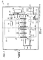
- Fig. 1 is a schematic plan view of an image forming apparatus in accordance with one embodiment of the invention
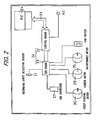
- Fig. 2 is a block diagram of a control system
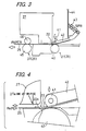
- Fig. 3 is a side view of a peripheral portion of an upstream side conveying mechanism 21.
- the present embodiment is an example of the case where an image forming apparatus is applied to an ink jet printer 20.
- the ink jet printer 20 is, for instance, connected to a personal computer 24 via a dedicated cable 23 and is configured so that print can be performed on a recording sheet 25 as a recording medium on the basis of a print command indicated by the personal computer 24.
- a printer driver for driving the ink jet printer 20 is installed in the personal computer 24.
- a downstream side of a conveying path H for the recording sheet 25 in Fig. 1 is defined as a frond direction
- an upstream side of the conveying path H is defined as a rear direction
- left and right sides of the conveying path H are defined as left and right directions, respectively.
- the ink jet printer 20 mainly comprises a cover member 26, an ink cartridge 27, a carriage (not shown), a carriage driving source 28, a conveying mechanism 29, a driving motor 30 for the conveying mechanism, a paper pressure flexible sheet 22 as guiding means, a recording sheet detecting sensor 31, a control unit 34 including a control board 32 and a sub board 33, a maintenance unit (not shown) and a maintenance motor 35.
- a recording sheet tray on which a plurality of recording sheets 25 can be stacked is attached to a back portion of the cover member 26 so as to incline in the rear direction so that the distal end thereof is positioned upward.
- a recording sheet discharge tray on which the printed recording sheet 25 is discharged and held is attached to a lower end portion of a front section of the cover member 26 so as to project toward the front direction.
- a recording sheet separation portion for separating the plurality of recording sheets 25 stacked on the recording sheet tray is provided on a lower end portion of the recording sheet discharge tray.
- an ink tank (not shown) is detachably held in the ink cartridge 27 and the ink cartridge 27 is configured so as to be detachable on an carriage and movable in right/left direction, i.e., a main scanning direction.
- the control unit 34 is configured so as to drive the carriage driving source 28 (a career motor 28) and spit out a droplet of ink on a desired print position of recording objective of the recording sheet 25 along with moving the ink cartridge 27 via the carriage in the main scanning direction on the basis of the print command.
- the ink cartridge 27, the carriage and the career motor 28 or the like correspond to recording means.
- the conveying mechanism 29 as recording medium conveying means capable of conveying the recording sheet 25 includes sequentially a sheet feeding roller 36, the upstream side conveying mechanism 21 as upstream side conveying means and a downstream side conveying mechanism 37 as downstream side conveying means along the conveying path H, which are arranged in the cover member 26, respectively.
- the sheet feeding roller 36 having a rotating shaft center extending in the right/left direction is arranged just ahead of the recording sheet tray so as to be rotatably around the rotating shaft center, and the sheet feeding roller 36 is rotationally driven in a clockwise direction R1 viewing from the right direction by the driving motor 30 for conveying mechanism (also named as a sheet feeding motor 30) via gears 38 and 39.
- the sheet feeding roller 36 applies pressure contact at a constant pressure to the recording sheet 25 arranged in the front row among the plurality of recording sheets 25 stacked on the recording sheet tray. Under this condition, the recording sheet 25 is fed one by one to the upstream side conveying mechanism 21 by rotationally driving the sheet feeding roller 36 in the clockwise direction R1 by the driving motor 30.
- the upstream side conveying mechanism 21 is arranged on the upstream side of the ink cartridge 27 along the conveying path H, and the upstream side conveying mechanism 21 including a platen roller 40, a plurality of recording sheet pressure rollers 41 as a pair of rotating rollers, a plurality of roller holders 42 for pressing a sheet of paper (hereinafter simply called "holder 42") and a plurality of coil springs 43.
- the recording sheet pressure rollers 41 and the platen roller 40 are configured so that they have a rotating shaft center extending in the right/left direction, respectively, and they are arranged parallel to each other vertically, and they can vertically sandwich the recording sheet 25 conveyed in substantially horizontal direction, and they are rotatable around each rotating shaft center.
- the platen roller 40 After the driving route (a pinion 30a and gears 38 and 39) of the sheet feeding roller 36 is changed to a driving route (a pinion 30a and gears 50 and 51) of the platen roller 40 by a driving system (not shown), the platen roller 40 is rotationally driven counterclockwise in Fig.3 via the gears 50 and 51 by the driving motor 30.
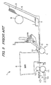
- Fig. 4 is an enlarged side view of the paper pressure flexible sheet 22
- Fig. 5 is an enlarged view of a main part showing a relation between the paper pressure flexible sheet 22 and the platen roller 40
- Fig. 6 is an enlarged view of the paper pressure flexible sheet 22 under the non-pressure contact condition.
- a frame member 44 is arranged in a substantially vertical direction inside the cover member 26.
- a plurality of platy holders 42 are arranged at appropriate intervals in the right/left direction and are supported so as to swing up and down.
- the holders 42 have a function of holding the recording sheet pressure roller 41 and a function of guiding the recording sheet 25.
- each coil spring 43 is arranged between one end of each holder 42 and the frame member 44.
- the holder 42 is configured so that the recording sheet pressure roller 41 which is rotatably supported on another end of the holder 42 abuts on the platen roller 40 at a constant pressure-contact force by spring force of the coil spring 43, namely, spring force acting in a direction in which one end of the holder 42 comes close to the frame member 44.
- Each paper pressure flexible sheet 22 is fixed toward a sub-scanning direction respectively in the bottom surface of each holder 42. These paper pressure flexible sheets 22 are arranged at constant intervals in the main scanning direction. Each paper pressure flexible sheet 22 is made of a material having appropriate elastic force, for instance, synthetic resin. A front end 22a of each paper pressure flexible sheet 22 is arranged so as to project from an ink jet orifice to a position which exists upstream by approximately 1 through 1.5 mm.
- the recording sheet pressure roller 41 is driven clockwise and the recording sheet 25 held between the recording sheet pressure roller 41 and the platen roller 40 is fed toward the downstream side of the conveying path H to be provided for print.
- the paper pressure flexible sheet 22 has a function of guiding the recording sheet 25 under the predetermined pressure-contact condition by spring force of the coil spring 43 and elastic force of the paper pressure flexible sheet 22.
- a part of each paper pressure flexible sheet 22 which exists on the rear side by, for instance, approximately 4.5 mm from the front end of each flexible sheet 22 is in pressure-contact with a position which exists downstream by approximately 2 mm in the conveying direction from the center, namely, the center of rotation of the platen roller 40 (See Fig. 5).
- the front end part 22a of the paper pressure flexible sheet 22 is attached so as to vertically bend by approximately 2 through 3 mm under the non-pressure contact condition, namely, free condition (See Fig. 6).
- the downstream side conveying mechanism 37 is arranged on the downstream side of the recording means along the conveying path H, and the downstream side conveying mechanism 37 has a function of feeding the recording sheet 25 fed from the upstream side conveying mechanism 21 toward the downstream side and finally discharging the recording sheet onto the recording sheet discharge tray.
- the downstream side conveying mechanism 37 includes a discharge roller 45 and a discharge pinch roller 46.
- the discharge pinch roller 46 and the discharge roller 45 are configured so that they have a rotating shaft center extending in the right/left direction, respectively, and they are arranged parallel to each other vertically, and they can vertically sandwich the recording sheet 25 conveyed in substantially horizontal direction, and they is rotatable around each rotating shaft center.
- the discharge roller 45 is rotationally driven counterclockwise in Fig.
- the discharge pinch roller 46 is configured so as to always abut on the discharge roller 45 with a constant pressure-contact force. Consequently, when the discharge roller 45 is rotationally driven counterclockwise, the discharge pinch roller 46 is driven clockwise and the recording sheet 25 sandwiched between the discharge pinch roller 46 and the discharge roller 45 is fed toward the downstream side of the conveying path H.
- the pressure-contact force generated between the discharge roller 45 and the discharge pinch roller 46 is set so as to become smaller than the pressure-contact force generated between the platen roller 40 and the recording sheet pressure roller 41 and so as to become larger than a pressure-contact force generated by elastic force of the paper pressure flexible sheet 22.
- the tail end of the recording sheet 25 is guided under the predetermined pressure-contact condition by the elastic force of the paper pressure flexible sheet 22 and the spring force of the coil spring 43. Therefore, it is possible to prevent the tail end of the recording sheet 25 from rising generated just after the tail end of the recording sheet 25 is apart from the platen roller 40. Consequently, the distance between an ink jet orifice 27a and the recording sheet 25 is always kept constant and variation of an impact point of ink can be suppressed and color unevenness in the case of polychromic print can be prevented from occurring.
- conveying force of the discharge roller 45 exceeds conveying force of the platen roller 40 generated by the paper pressure flexible sheet 22 because the pressure-contact force of each member is set as mentioned above. Therefore, a change of conveying speed of the recording sheet 25 can be suppressed as much as possible, and a change of conveying amount of the recording sheet 25 can be prevented, and deviation of a print position caused by the change of conveying amount of the recording sheet 25 can be prevented. Consequently, cross lines in the main scanning direction of the recording sheet 25 or color unevenness in the case of polychromic print can be certainly prevented from occurring.
- the recording sheet detecting sensor 31 is provided in a substantial middle part of the main scanning direction of the recording sheet 25.
- the recording sheet 25 is conveyed by the sheet feeding roller 36 to a position where the recording sheet detecting sensor 31 is turned on, and detection of the recording sheet 25 is performed by turning the recording sheet detecting sensor 31 on. Subsequently, the recording sheet 25 is conveyed until the recording sheet 25 abuts on the platen roller 40 and then the recording sheet 25 is stopped.
- the recording sheet detecting sensor 31 is turned off and then print is similarly performed on the recording sheet 25 on the basis of print data or the like.
- Fig. 7 is a flow chart of a series of operation sequences executed at the control unit 34.
- Fig. 8 is a schematic plan view of print dot made by the ink jet printer 20 in accordance with one embodiment of the invention.
- step S1 operation sequence is started, and at step S2 a standby state is come into, and then at step 3 whether a print-command is issued from the personal computer 24 is judged.
- the operation sequence proceeds to step S4, and the above mentioned operation of feeding the recording sheet 25 is performed, and the leading end of the recording sheet 25 is conveyed and stopped to a print starting position by the upstream side conveying mechanism 21.
- step S5 the maintenance motor 35 is driven and the ink cartridge 27 is maintained by a maintenance unit.
- step S6 the operation sequence proceeds to step S6 and the ink cartridge 27 is moved from the initial home position P1 to a print standby position P2 by the career motor 28.
- the ink cartridge 27 spits out ink on the basis of print data and various printing data which are previously set printing data, the printing data, for instance, being a desired recording objective among a plain paper, a post card and a photo or the like and a desired standard size among standard sizes of A4, A5 or the like of the recording sheet 25 along with moving from right to left in the main scanning direction from the print start position for the recording sheet 25.
- the ink cartridge 27 is moved from left to right in the main scanning direction and is returned to the print standby position P2.
- step S9 the recording sheet 25 is accurately conveyed by one line in the downstream side of the conveying direction, namely, in the sub-scanning direction and subsequently print on the second line is performed similarly as described above.
- print is performed on each line in the main scanning direction on the basis of print data and printing data along with sequentially conveying the recording sheet 25 by one line to the discharge roller 45 by the platen roller 40 of the upstream side conveying mechanism 21.
- step S10 when the tail end of the recording sheet 25 passes through the recording sheet detecting sensor 31 and the control unit 34 detects that the recording sheet detecting sensor 31 is turned off, print corresponding to one line is terminated.
- step S11 after operation sequence proceeds to step S11, and after the tail end of the recording sheet 25 is apart from the platen roller 40 and the recording sheet pressure roller 41 in a state where the recording sheet 25 is in pressure-contact therewith toward the downstream side of the conveying path H, the recording sheet 25 is conveyed by one line only by the downstream side conveying mechanism 37 and then print is performed along the main scanning direction.
- the recording sheet 25 is conveyed until the last line in the sub-scanning direction only by the downstream side conveying mechanism 37 and then print is performed on the basis of print data and printing data.
- a discharge operation of the printed recording sheet 25 is performed by the downstream side conveying mechanism 37 and the recording sheet 25 is discharged onto the recording sheet discharge tray.
- step S13 when it is judged that continuous print is performed, the operation sequence is returned to step S4, whereas when it is judged that the continuous print is not performed, the operation sequence is returned to step S1.
- the paper pressure flexible sheet 22 guides the recording sheet 25 under the predetermined pressure-contact condition. Therefore, such a problem of the change of conveying amount of the recording sheet 25 caused by change of conveying speed of the recording sheet 25 as mentioned concerning the conventional technique can be previously solved. Accordingly, as shown in Fig. 8, print of a black circle and a white circle of print dot is recorded on a normal position without adverse effect on print caused by conveying unevenness of the recording sheet 25 occurring at the moment that the recording sheet 25 is apart from the platen roller 40 and the recording pressing roller 41.
- the guiding means is not always restricted to the sheet of synthetic resin, and a metal having appropriate elastic force (for instance, a flat spring or a tension spring) may be applied to the guiding means.
- a metal having appropriate elastic force for instance, a flat spring or a tension spring
- the guide means mechanism, having a rotating shaft, in which a rotational acting part is provided on one side and a guiding portion being in contact with (or allowable to be not in contact with), for instance, the platen roller is provided on another side, and the tail end of the recording sheet is prevented from rising by the guiding portion, may be applied.
- the three paper pressure flexible sheets 22 are provided in holders 42, respectively, but the embodiment is not restricted to these three paper pressure flexible sheets 22, and at least two, i.e., right and left, paper pressure flexible sheets 22 may be provided for each holder 42, whereby it is possible to use members efficiently. There is a case where various partial changes in the embodiment are performed within the extent of no deviation from the scope of the claims.
Landscapes
- Ink Jet (AREA)
- Handling Of Cut Paper (AREA)
- Feeding Of Articles By Means Other Than Belts Or Rollers (AREA)
Abstract
An object of the invention is to provide an image
forming apparatus wherein quality of an image can be
improved at the time of recording the image on a recording
medium and its configuration can be simplified. The image
forming apparatus comprises an ink cartridge (27) capable
of print on a recording sheet (25), an upstream side
conveying mechanism (21), a downstream side conveying
mechanism (37) and a paper pressure flexible sheet (22) for
guiding the recording sheet (25) under a predetermined
pressure-contact condition when the tail end of the
recording sheet (25) passes through the upstream side
conveying mechanism (21). Thereby, The conventional
problem of a change of conveying amount of the recording
sheet (25) caused by a change of conveying speed of the
recording sheet (25) can be previously solved, and a
relative distance of the recording sheet (25) to the ink
cartridge (27) can be always stabilized.
Description
The present invention relates to an image forming
apparatus, for instance, to technique preferably used for a
sheet feed mechanism of an ink jet printer or the like.
Such an ink jet printer as an image forming apparatus
is made available that an image is recorded on a recording
sheet by spitting out a droplet of ink on a desired print
position of a recording objective along with moving an ink
cartridge in a main scanning direction through a carriage
with respect to the recording sheet and conveying the
recording sheet in a sub-scanning direction, according to a
print command indicated by, e.g., a personal computer. Fig.
9 is a schematic view for explaining a conventional ink jet
printer 1. Figs. 10A to 10C are enlarged views of a main
part showing a relation between an upstream side conveying
mechanism 2 and a recording sheet 3. Fig. 11 is a view for
explaining a condition of a position near a tail end of the
recording sheet 3 just after the recording sheet 3 is apart
from the upstream side conveying mechanism 2. Fig. 12 is a
view for explaining a relative position of each portion
with respect to a platen roller 4 in the conventional ink
jet printer 1.
In the case where print is performed on the recording
sheet 3 as a print objective, when after a plurality of
sheets of recording sheet 3 is set on a recording sheet
tray 5, for instance, a print command is indicated by a
personal computer, print data is transferred to the ink jet
printer 1. Next, a preset maintenance operation is
performed for an ink cartridge 6 and then the ink cartridge
6 is moved from a home position to a print start position
of the ink cartridge 6. Next, one sheet of recording sheet
3 is separated and taken out from the recording sheet tray
5 by a recording sheet separating portion 7. One recording
sheet 3 is conveyed by a sheet feeding roller 8 to a
position where a recording sheet detection sensor 9 is
turned on and the recording sheet 3 is detected by turning
the recording sheet detection sensor 9 on.
Subsequently, the recording sheet 3 is conveyed at a
certain distance until the recording sheet 3 abuts on a
platen roller 4 and then the recording sheet 3 is stopped.
Next, a driving route of the sheet feed roller 8 is changed
to that of the platen roller 4 by a driving system (not
shown). The recording sheet 3 is conveyed to a position
between the platen roller 4 and a recording sheet pressure
roller 10 which is in pressure-contact with the platen
roller 4. Subsequently, the recording sheet 3 is stopped
once in a state where a leading end end of the recording
sheet 3 is conveyed to the print start point by rotational
driving of the platen roller 4. The ink cartridge 6
performs print by spitting out an ink on the basis of the
print data along with moving the ink cartridge 6 from the
print start position in a main scanning direction
perpendicular to a conveying direction of the recording
sheet 3 by a carriage (not shown). When print for one line
is terminated, the ink cartridge 6 is returned to a
predetermined standby position. Next, the recording sheet
3 is accurately fed by an amount corresponding to one line
in the conveying direction as a sub-scanning direction by
rotation driving of the platen roller 4 and print for the
second line is performed in the state where the recording
sheet 3 is stopped in the same way as mentioned above.
A discharge roller 11 and a discharge pinch roller 12
(also called "star roller") are arranged on a downstream
side of an ink spitting position of the ink cartridge 6
along a conveying path and these rollers 11 and 12 are
rotated in synchronization with the rotation of the platen
roller 4. A pressure-contact force generated between the
discharge roller 11 and the discharge pinch roller 12 is
set so as to become smaller than that generated between the
platen roller 4 and the recording sheet pressure roller 10.
The recording sheet 3 is conveyed by one line by the platen
roller 4, and the recording sheet 3 is conveyed in the sub-scanning
direction along with performing print on the basis
of print data. Subsequently, when the leading end of the
recording sheet 3 reaches the discharge roller 11, the
recording sheet 3 is conveyed by one line in the sub-scanning
direction by the platen roller 4 and the discharge
roller 11, and print is performed by spitting out the ink
from the ink cartridge 6 on the basis of print data.
When a tail end of the recording sheet 3 passes
through the recording sheet detection sensor 9, the
recording sheet detection sensor 9 is turned off, and after
the recording sheet detection sensor 9 is turned off, print
is also performed for the recording sheet 3 on the basis of
print data. Subsequently, when more print is performed on
the basis of print data, the tail end of the recording
sheet 3 is apart from the platen roller 4, and thereafter
print is performed to the tail end of the recording sheet 3
along with conveying the recording sheet 3 by only the
discharge roller 11, and then print is terminated.
Subsequently, the recording sheet 3 is discharged onto a
recording sheet tray 13 by the discharge roller 11.
According to such a conventional technique, there is
a problem that a subtle change of conveying speed occurs at
the moment that the tail end 3a of the recording sheet 3 is
apart from the platen roller 4, which leads to a change of
a conveying amount of the recording sheet 3. Fig. 13 is a
schematic plan view of print dots made by the conventional
ink jet printer 1. In Fig. 13, a black circle and a white
circle represent dots of ink spat out. As shown in Fig.13,
since a print position is deviated from a normal print
position due to the change of the amount of conveying the
recording sheet 3, cross lines in the main scanning
direction of the recording sheet 3 or color unevenness in
the case of polychromic print occurs. In other words, in
the normal print condition, an ink is spat out from a
nozzle of the ink cartridge 6 and a black circle and a
white circle are printed alternately. (see Fig. 8)
Correspondingly, in the conventional technique, a
phenomenon that the black circle and the white circle are
not printed alternately due to the change of the amount of
conveying the recording sheet 3 occurs, and the black
circle and the white circle are separated from each other
or overlaps with each other. Therefore, cross lines in the
main scanning direction of the recording sheet 3 or color
unevenness in the case of polychromic print occurs.
In addition, just after the tail end 3a of the
recording sheet 3 is apart from the platen roller 4, the
tail end 3a rises a little upward and a distance CP between
an ink jet orifice 6a and the tail end 3a of the recording
sheet 3 is changed. Consequently, an impact point of ink
varies and color unevenness in the case of polychromic
print occurs. To eliminate these cross lines or uneven
colors, there is such a method that a recording sheet
having longer size in the sub-scanning direction than a
predetermined size is previously prepared and such a
countermeasure is taken that the tail end of the recording
sheet is prevented from being apart from a platen roller in
the middle of print and an unnecessary part of the tail end
is cut off after print is terminated. However, the
recording sheet having longer size than the predetermined
size should be prepared, and besides, a work for cutting
off an unnecessary part of the recording sheet should be
required, so that working efficiency becomes low.
Consequently, an object of the invention is to
provide an image forming apparatus enabling quality of an
image at the time of recording the image in a recording
medium to be improved and also enabling its configuration
to be simplified.
The invention provides an image forming apparatus
comprising:
According to the invention, when the desired image is
recorded on the recording medium, the recording medium is
conveyed to the upstream side conveying means arranged on
the upstream side of the recording means and then the image
is recorded on the recording medium in cooperation with an
operation of the upstream side conveying means. In a state
where the recording medium is conveyed to the downstream
side conveying means on the downstream side of the
recording means, the image is recorded on the recording
medium similarly as mentioned above in cooperation with
operations of the upstream side conveying means and the
downstream side conveying means. And then, when the tail
end of the recording medium passes through the upstream
side conveying means or after the tail end of the recording
medium passes through the upstream side conveying means,
the guiding means guides the recording medium under the
predetermined pressure-contact condition. Therefore, the
problem of the change of the conveying amount of the
recording medium due to the change of conveying speed of
the recording medium as mentioned concerning the
conventional technique can be previously solved, and
besides, a relative distance of the recording medium to the
recording means can be always stabilized.
According to the invention, when the tail end of the
recording medium passes through the upstream side conveying
means or after the tail end of the recording medium passes
through the upstream side conveying means, the guiding
means guides the recording medium under the predetermined
pressure-contact condition. Therefore, the problem of the
change of conveying amount of the recording medium due to
the change of conveying speed of the recording medium as
mentioned concerning the conventional technique can be
previously solved, so that deviation of a recording
position from the normal position can be prevented from
occurring. For instance, cross lines in the main scanning
direction of the recording medium or color unevenness in
the case of polychromic printing can be certainly prevented
from occurring. In addition, since a relative distance of
the recording medium to the recording means can be always
stabilized, variation of an impact point of a droplet can
be suppressed and color unevenness can be prevented from
occurring in the case of polychromic print.
In addition, in the invention it is preferred that
the guiding means is provided in the upstream side
conveying means.
According to the invention, when the image is
recorded on the tail end of the recording medium, quality
of the image can be improved and its configuration can be
simplified.
In addition, according to the invention, since the
guiding means is provided in the upstream side conveying
means, the quality of the image can be improved at the time
of recording the image on the tail end of the recording
medium and its configuration can be simplified.
In addition, in the invention it is preferred that
the upstream side conveying means comprises: a pair of
rotating rollers capable of sandwiching the recording
medium between the rollers and being rotatable; and a
roller holder supporting one rotating roller which is
elastically energized against another rotating roller, and
that the guiding means is provided in the roller holder.
According to the invention, even in a state where the
tail end of the recording medium is apart from one rotating
roller which is elastically energized against another
rotating roller, the guiding means provided in the roller
holder can guide at least the tail end of the recording
medium by means of elastic force under the predetermined
pressure-contact condition.
In the invention it is preferable that the guiding
means is formed of a sheet of synthetic resin.
In the invention it is preferable that the guiding
means is formed of a metal.
In the invention it is preferable that the guiding
means guides the tail end of the recording medium between
the upstream side conveying means and the recording means
under the predetermined pressure-contact condition.
Other and further objects, features, and advantages
of the invention will be more explicit from the following
detailed description taken with reference to the drawings
wherein:
Now referring to the drawings, preferred embodiments
of the invention are described below.
Fig. 1 is a schematic plan view of an image forming
apparatus in accordance with one embodiment of the
invention, and Fig. 2 is a block diagram of a control
system, and Fig. 3 is a side view of a peripheral portion
of an upstream side conveying mechanism 21. The present
embodiment is an example of the case where an image forming
apparatus is applied to an ink jet printer 20. The ink jet
printer 20 is, for instance, connected to a personal
computer 24 via a dedicated cable 23 and is configured so
that print can be performed on a recording sheet 25 as a
recording medium on the basis of a print command indicated
by the personal computer 24. In addition, a printer driver
for driving the ink jet printer 20 is installed in the
personal computer 24. Hereinafter, a downstream side of a
conveying path H for the recording sheet 25 in Fig. 1 is
defined as a frond direction, and an upstream side of the
conveying path H is defined as a rear direction, and left
and right sides of the conveying path H are defined as left
and right directions, respectively. The following
explanation is given according to the definition.
The ink jet printer 20 mainly comprises a cover
member 26, an ink cartridge 27, a carriage (not shown), a
carriage driving source 28, a conveying mechanism 29, a
driving motor 30 for the conveying mechanism, a paper
pressure flexible sheet 22 as guiding means, a recording
sheet detecting sensor 31, a control unit 34 including a
control board 32 and a sub board 33, a maintenance unit
(not shown) and a maintenance motor 35. A recording sheet
tray on which a plurality of recording sheets 25 can be
stacked is attached to a back portion of the cover member
26 so as to incline in the rear direction so that the
distal end thereof is positioned upward. A recording sheet
discharge tray on which the printed recording sheet 25 is
discharged and held is attached to a lower end portion of a
front section of the cover member 26 so as to project
toward the front direction. In addition, a recording sheet
separation portion for separating the plurality of
recording sheets 25 stacked on the recording sheet tray is
provided on a lower end portion of the recording sheet
discharge tray.
Inside the cover member 26, an ink tank (not shown)
is detachably held in the ink cartridge 27 and the ink
cartridge 27 is configured so as to be detachable on an
carriage and movable in right/left direction, i.e., a main
scanning direction. The control unit 34 is configured so
as to drive the carriage driving source 28 (a career motor
28) and spit out a droplet of ink on a desired print
position of recording objective of the recording sheet 25
along with moving the ink cartridge 27 via the carriage in
the main scanning direction on the basis of the print
command. The ink cartridge 27, the carriage and the career
motor 28 or the like correspond to recording means.
The conveying mechanism 29 as recording medium
conveying means capable of conveying the recording sheet 25
includes sequentially a sheet feeding roller 36, the
upstream side conveying mechanism 21 as upstream side
conveying means and a downstream side conveying mechanism
37 as downstream side conveying means along the conveying
path H, which are arranged in the cover member 26,
respectively. The sheet feeding roller 36 having a
rotating shaft center extending in the right/left direction
is arranged just ahead of the recording sheet tray so as to
be rotatably around the rotating shaft center, and the
sheet feeding roller 36 is rotationally driven in a
clockwise direction R1 viewing from the right direction by
the driving motor 30 for conveying mechanism (also named as
a sheet feeding motor 30) via gears 38 and 39. The sheet
feeding roller 36 applies pressure contact at a constant
pressure to the recording sheet 25 arranged in the front
row among the plurality of recording sheets 25 stacked on
the recording sheet tray. Under this condition, the
recording sheet 25 is fed one by one to the upstream side
conveying mechanism 21 by rotationally driving the sheet
feeding roller 36 in the clockwise direction R1 by the
driving motor 30.
The upstream side conveying mechanism 21 is arranged
on the upstream side of the ink cartridge 27 along the
conveying path H, and the upstream side conveying mechanism
21 including a platen roller 40, a plurality of recording
sheet pressure rollers 41 as a pair of rotating rollers, a
plurality of roller holders 42 for pressing a sheet of
paper (hereinafter simply called "holder 42") and a
plurality of coil springs 43. In other words, the
recording sheet pressure rollers 41 and the platen roller
40 are configured so that they have a rotating shaft center
extending in the right/left direction, respectively, and
they are arranged parallel to each other vertically, and
they can vertically sandwich the recording sheet 25
conveyed in substantially horizontal direction, and they
are rotatable around each rotating shaft center. After the
driving route (a pinion 30a and gears 38 and 39) of the
sheet feeding roller 36 is changed to a driving route (a
pinion 30a and gears 50 and 51) of the platen roller 40 by
a driving system (not shown), the platen roller 40 is
rotationally driven counterclockwise in Fig.3 via the gears
50 and 51 by the driving motor 30.
Fig. 4 is an enlarged side view of the paper pressure
flexible sheet 22, and Fig. 5 is an enlarged view of a main
part showing a relation between the paper pressure flexible
sheet 22 and the platen roller 40, and Fig. 6 is an
enlarged view of the paper pressure flexible sheet 22 under
the non-pressure contact condition. A frame member 44 is
arranged in a substantially vertical direction inside the
cover member 26. On an lower portion of the frame member
44, a plurality of platy holders 42 are arranged at
appropriate intervals in the right/left direction and are
supported so as to swing up and down. The holders 42 have
a function of holding the recording sheet pressure roller
41 and a function of guiding the recording sheet 25. In
detail, each coil spring 43 is arranged between one end of
each holder 42 and the frame member 44. The holder 42 is
configured so that the recording sheet pressure roller 41
which is rotatably supported on another end of the holder
42 abuts on the platen roller 40 at a constant pressure-contact
force by spring force of the coil spring 43, namely,
spring force acting in a direction in which one end of the
holder 42 comes close to the frame member 44.
Three rectangular paper pressure flexible sheets 22
are fixed toward a sub-scanning direction respectively in
the bottom surface of each holder 42. These paper pressure
flexible sheets 22 are arranged at constant intervals in
the main scanning direction. Each paper pressure flexible
sheet 22 is made of a material having appropriate elastic
force, for instance, synthetic resin. A front end 22a of
each paper pressure flexible sheet 22 is arranged so as to
project from an ink jet orifice to a position which exists
upstream by approximately 1 through 1.5 mm. When the
platen roller 40 is rotationally driven counterclockwise as
mentioned above in a state where the platen roller 40 abuts
on the recorded sheet pressing roller 41, the recording
sheet pressure roller 41 is driven clockwise and the
recording sheet 25 held between the recording sheet
pressure roller 41 and the platen roller 40 is fed toward
the downstream side of the conveying path H to be provided
for print.
When the tail end of the recording sheet 25 passes
between the recording sheet pressure roller 41 and the
platen roller 40, or after the tail end of the recording
sheet 25 passes between the recording sheet pressure roller
41 and the platen roller 40, the paper pressure flexible
sheet 22 has a function of guiding the recording sheet 25
under the predetermined pressure-contact condition by
spring force of the coil spring 43 and elastic force of the
paper pressure flexible sheet 22. As a concrete example, a
part of each paper pressure flexible sheet 22 which exists
on the rear side by, for instance, approximately 4.5 mm
from the front end of each flexible sheet 22 is in
pressure-contact with a position which exists downstream by
approximately 2 mm in the conveying direction from the
center, namely, the center of rotation of the platen roller
40 (See Fig. 5). In this case, the front end part 22a of
the paper pressure flexible sheet 22 is attached so as to
vertically bend by approximately 2 through 3 mm under the
non-pressure contact condition, namely, free condition (See
Fig. 6).
The downstream side conveying mechanism 37 is
arranged on the downstream side of the recording means
along the conveying path H, and the downstream side
conveying mechanism 37 has a function of feeding the
recording sheet 25 fed from the upstream side conveying
mechanism 21 toward the downstream side and finally
discharging the recording sheet onto the recording sheet
discharge tray. The downstream side conveying mechanism 37
includes a discharge roller 45 and a discharge pinch roller
46. The discharge pinch roller 46 and the discharge roller
45 are configured so that they have a rotating shaft center
extending in the right/left direction, respectively, and
they are arranged parallel to each other vertically, and
they can vertically sandwich the recording sheet 25
conveyed in substantially horizontal direction, and they is
rotatable around each rotating shaft center. The discharge
roller 45 is rotationally driven counterclockwise in Fig. 4
in synchronization with the platen roller 40 via gears 47,
48 and 49 by the driving motor 30 mentioned above. The
discharge pinch roller 46 is configured so as to always
abut on the discharge roller 45 with a constant pressure-contact
force. Consequently, when the discharge roller 45
is rotationally driven counterclockwise, the discharge
pinch roller 46 is driven clockwise and the recording sheet
25 sandwiched between the discharge pinch roller 46 and the
discharge roller 45 is fed toward the downstream side of
the conveying path H. In addition, the pressure-contact
force generated between the discharge roller 45 and the
discharge pinch roller 46 is set so as to become smaller
than the pressure-contact force generated between the
platen roller 40 and the recording sheet pressure roller 41
and so as to become larger than a pressure-contact force
generated by elastic force of the paper pressure flexible
sheet 22.
In particular, even after the tail end of the
recording sheet 25 is apart from the platen roller 40 and
the recording sheet pressure roller 41 under the pressure-contact
condition of the recording sheet 25 toward the
downstream side of the conveying path H, the tail end of
the recording sheet 25 is guided under the predetermined
pressure-contact condition by the elastic force of the
paper pressure flexible sheet 22 and the spring force of
the coil spring 43. Therefore, it is possible to prevent
the tail end of the recording sheet 25 from rising
generated just after the tail end of the recording sheet 25
is apart from the platen roller 40. Consequently, the
distance between an ink jet orifice 27a and the recording
sheet 25 is always kept constant and variation of an impact
point of ink can be suppressed and color unevenness in the
case of polychromic print can be prevented from occurring.
Moreover, conveying force of the discharge roller 45
exceeds conveying force of the platen roller 40 generated
by the paper pressure flexible sheet 22 because the
pressure-contact force of each member is set as mentioned
above. Therefore, a change of conveying speed of the
recording sheet 25 can be suppressed as much as possible,
and a change of conveying amount of the recording sheet 25
can be prevented, and deviation of a print position caused
by the change of conveying amount of the recording sheet 25
can be prevented. Consequently, cross lines in the main
scanning direction of the recording sheet 25 or color
unevenness in the case of polychromic print can be
certainly prevented from occurring.
In the frame member 44, the recording sheet detecting
sensor 31 is provided in a substantial middle part of the
main scanning direction of the recording sheet 25. The
recording sheet 25 is conveyed by the sheet feeding roller
36 to a position where the recording sheet detecting sensor
31 is turned on, and detection of the recording sheet 25 is
performed by turning the recording sheet detecting sensor
31 on. Subsequently, the recording sheet 25 is conveyed
until the recording sheet 25 abuts on the platen roller 40
and then the recording sheet 25 is stopped. When most of
printing on the recording sheet 25 is terminated and then
the tail end of the recording sheet 25 passes through the
recording sheet detecting sensor 31, the recording sheet
detecting sensor 31 is turned off and then print is
similarly performed on the recording sheet 25 on the basis
of print data or the like.
Fig. 7 is a flow chart of a series of operation
sequences executed at the control unit 34. Wherein, Si (i
= 1, 2, 3) denotes a step. Fig. 8 is a schematic plan view
of print dot made by the ink jet printer 20 in accordance
with one embodiment of the invention. At step S1,
operation sequence is started, and at step S2 a standby
state is come into, and then at step 3 whether a print-command
is issued from the personal computer 24 is judged.
When print command exists, the operation sequence proceeds
to step S4, and the above mentioned operation of feeding
the recording sheet 25 is performed, and the leading end of
the recording sheet 25 is conveyed and stopped to a print
starting position by the upstream side conveying mechanism
21. With this operation, a nozzle jet surface of the ink
cartridge 27 arranged on a home position P1 is cleaned
using a wiper rubber (not shown) and ink is jetted from the
nozzle. Subsequently, at step S5 the maintenance motor 35
is driven and the ink cartridge 27 is maintained by a
maintenance unit. Subsequently, the operation sequence
proceeds to step S6 and the ink cartridge 27 is moved from
the initial home position P1 to a print standby position P2
by the career motor 28.
Subsequently, at step S7 the ink cartridge 27 spits
out ink on the basis of print data and various printing
data which are previously set printing data, the printing
data, for instance, being a desired recording objective
among a plain paper, a post card and a photo or the like
and a desired standard size among standard sizes of A4, A5
or the like of the recording sheet 25 along with moving
from right to left in the main scanning direction from the
print start position for the recording sheet 25. After
print on the first line is terminated, at step S8 the ink
cartridge 27 is moved from left to right in the main
scanning direction and is returned to the print standby
position P2. Subsequently, at step S9 the recording sheet
25 is accurately conveyed by one line in the downstream
side of the conveying direction, namely, in the sub-scanning
direction and subsequently print on the second
line is performed similarly as described above. In this
way, print is performed on each line in the main scanning
direction on the basis of print data and printing data
along with sequentially conveying the recording sheet 25 by
one line to the discharge roller 45 by the platen roller 40
of the upstream side conveying mechanism 21. When the
recording sheet 25 is conveyed to the discharge roller 45
of the downstream side conveying mechanism 37, print is
performed on each line in the main scanning direction on
the basis of print data and printing data along with
sequentially conveying the recording sheet 25 by one line
in the sub-scanning direction in cooperation with the
upstream side conveying mechanism 21 and the downstream
side conveying mechanism 37.
Subsequently, at step S10 when the tail end of the
recording sheet 25 passes through the recording sheet
detecting sensor 31 and the control unit 34 detects that
the recording sheet detecting sensor 31 is turned off,
print corresponding to one line is terminated.
Subsequently, after operation sequence proceeds to step S11,
and after the tail end of the recording sheet 25 is apart
from the platen roller 40 and the recording sheet pressure
roller 41 in a state where the recording sheet 25 is in
pressure-contact therewith toward the downstream side of
the conveying path H, the recording sheet 25 is conveyed by
one line only by the downstream side conveying mechanism 37
and then print is performed along the main scanning
direction. Subsequently, the recording sheet 25 is
conveyed until the last line in the sub-scanning direction
only by the downstream side conveying mechanism 37 and then
print is performed on the basis of print data and printing
data. Subsequently, at step S12 a discharge operation of
the printed recording sheet 25 is performed by the
downstream side conveying mechanism 37 and the recording
sheet 25 is discharged onto the recording sheet discharge
tray. Subsequently, at step S13 when it is judged that
continuous print is performed, the operation sequence is
returned to step S4, whereas when it is judged that the
continuous print is not performed, the operation sequence
is returned to step S1.
According to the ink jet printer 20 described above,
when the tail end of the recording sheet 25 passes through
the upstream side conveying mechanism 21 or after the tail
end of the recording sheet 25 passes through the upstream
side conveying mechanism 21, the paper pressure flexible
sheet 22 guides the recording sheet 25 under the
predetermined pressure-contact condition. Therefore, such
a problem of the change of conveying amount of the
recording sheet 25 caused by change of conveying speed of
the recording sheet 25 as mentioned concerning the
conventional technique can be previously solved.
Accordingly, as shown in Fig. 8, print of a black circle
and a white circle of print dot is recorded on a normal
position without adverse effect on print caused by
conveying unevenness of the recording sheet 25 occurring at
the moment that the recording sheet 25 is apart from the
platen roller 40 and the recording pressing roller 41.
Consequently, cross lines in the main scanning direction of
the recording sheet 25 or color unevenness in the case of
polychromic print can be certainly prevented from occurring.
In addition, a relative distance of the recording sheet 25
to the ink jet orifice 27a of the ink cartridge 27 can be
always stabilized and therefore variation of an impact
point of ink can be suppressed and color unevenness in the
case of polychromic print can be prevented from occurring.
In addition, since the paper pressure flexible sheet 22 is
provided in the holder 42 of the upstream side conveying
mechanism 21, quality of print can be improved at the time
of performing the print on the tail end of the recording
sheet 25 and its configuration can be simplified.
As other embodiment in accordance with the invention,
the guiding means is not always restricted to the sheet of
synthetic resin, and a metal having appropriate elastic
force (for instance, a flat spring or a tension spring) may
be applied to the guiding means. In addition, as the guide
means, mechanism, having a rotating shaft, in which a
rotational acting part is provided on one side and a
guiding portion being in contact with (or allowable to be
not in contact with), for instance, the platen roller is
provided on another side, and the tail end of the recording
sheet is prevented from rising by the guiding portion, may
be applied. In the embodiment, the three paper pressure
flexible sheets 22 are provided in holders 42, respectively,
but the embodiment is not restricted to these three paper
pressure flexible sheets 22, and at least two, i.e., right
and left, paper pressure flexible sheets 22 may be provided
for each holder 42, whereby it is possible to use members
efficiently. There is a case where various partial changes
in the embodiment are performed within the extent of no
deviation from the scope of the claims.
The invention may be embodied in other specific forms
without departing from the spirit or essential
characteristics thereof. The present embodiments are
therefore to be considered in all respects as illustrative
and not restrictive, the scope of the invention being
indicated by the appended claims rather than by the
foregoing description and all changes which come within the
meaning and the range of equivalency of the claims are
therefore intended to be embraced therein.
Claims (6)
- An image forming apparatus comprising:recording means (27, 28) for recording a desired image on a recording medium (25);recording medium conveying means (29) capable of conveying the recording medium (25), including upstream side conveying means (21) and arranged on an upstream side of the recording means (27, 28) along a conveying path (H) and downstream conveying means (37) arranged on a downstream side of the recording means (27, 28) along the conveying path (H); andguiding means (22) for guiding the recording medium (25) under a predetermined pressure-contact condition when a tail end of the recording medium (25) passes through the upstream side conveying means (21) or after the tail end of the recording medium (25) passes through the upstream side conveying means (21).
- The image forming apparatus of claim 1, wherein the guiding means (22) is provided in the upstream side conveying means (21).
- The image forming apparatus of claim 1, wherein the upstream side conveying means (21) comprises:wherein the guiding means (22) is provided in the roller holder (42).a pair of rotating rollers (40, 41) capable of sandwiching the recording medium (25) between the rollers and being rotatable; anda roller holder (42) supporting one rotating roller (41) which is elastically energized against another rotating roller (40),
- The image forming apparatus of claim 1, wherein the guiding means (22) is formed of a sheet of synthetic resin.
- The image forming apparatus of claim 1, wherein the guiding means (22) is formed of a metal.
- The image forming apparatus of claim 1, wherein the guiding means (22) guides the tail end of the recording medium (25) between the upstream side conveying means (21) and the recording means (27, 28) under the predetermined pressure-contact condition.
Applications Claiming Priority (2)
| Application Number | Priority Date | Filing Date | Title |
|---|---|---|---|
| JP2002043858 | 2002-02-20 | ||
| JP2002043858A JP2003237163A (en) | 2002-02-20 | 2002-02-20 | Image forming device |
Publications (1)
| Publication Number | Publication Date |
|---|---|
| EP1338427A2 true EP1338427A2 (en) | 2003-08-27 |
Family
ID=27655272
Family Applications (1)
| Application Number | Title | Priority Date | Filing Date |
|---|---|---|---|
| EP03003771A Withdrawn EP1338427A2 (en) | 2002-02-20 | 2003-02-19 | Image forming apparatus |
Country Status (5)
| Country | Link |
|---|---|
| US (1) | US20030174194A1 (en) |
| EP (1) | EP1338427A2 (en) |
| JP (1) | JP2003237163A (en) |
| CN (1) | CN1443649A (en) |
| TW (1) | TW200303826A (en) |
Families Citing this family (6)
| Publication number | Priority date | Publication date | Assignee | Title |
|---|---|---|---|---|
| JP2004292092A (en) * | 2003-03-26 | 2004-10-21 | Brother Ind Ltd | Paper guide device and printing device having the same |
| CN103106758B (en) * | 2011-11-11 | 2015-11-25 | 山东新北洋信息技术股份有限公司 | Pressboard assembly, paper-pressing mechanism and laminated medium processing unit |
| EP3148905B1 (en) | 2014-05-28 | 2021-10-27 | Hewlett-Packard Development Company, L.P. | Print-medium buffering |
| US9925763B2 (en) * | 2016-01-21 | 2018-03-27 | Seiko Epson Corporation | Print system |
| JP6380604B2 (en) * | 2017-04-24 | 2018-08-29 | セイコーエプソン株式会社 | Liquid ejector |
| CN114701268B (en) * | 2022-04-20 | 2024-02-20 | 郑州新世纪数码科技股份有限公司 | Two-stage adjusting high-precision pinch roller adjusting structure and wide digital printer |
-
2002
- 2002-02-20 JP JP2002043858A patent/JP2003237163A/en active Pending
-
2003
- 2003-02-19 EP EP03003771A patent/EP1338427A2/en not_active Withdrawn
- 2003-02-20 TW TW092103512A patent/TW200303826A/en unknown
- 2003-02-20 US US10/368,418 patent/US20030174194A1/en not_active Abandoned
- 2003-02-20 CN CN03110773.7A patent/CN1443649A/en active Pending
Also Published As
| Publication number | Publication date |
|---|---|
| US20030174194A1 (en) | 2003-09-18 |
| TW200303826A (en) | 2003-09-16 |
| JP2003237163A (en) | 2003-08-27 |
| CN1443649A (en) | 2003-09-24 |
Similar Documents
| Publication | Publication Date | Title |
|---|---|---|
| US7533962B2 (en) | Ink jet printing apparatus and ink jet printing method | |
| US6682190B2 (en) | Controlling media curl in print-zone | |
| CN102189827B (en) | Recording device and recording method | |
| US6808259B2 (en) | Controlling media curl in print-zone | |
| US20030174194A1 (en) | Image forming apparatus | |
| JP2025085777A (en) | Printer | |
| JP5289021B2 (en) | Inkjet recording device | |
| JP5327448B2 (en) | Image forming apparatus | |
| US7992991B2 (en) | Image forming apparatus | |
| JP3741243B2 (en) | Inkjet recording device | |
| JP4583876B2 (en) | Image forming apparatus and program | |
| JP5821441B2 (en) | Image forming apparatus | |
| JPH05221103A (en) | Image recording apparatus | |
| JP4957004B2 (en) | Inkjet recording device | |
| JP4027002B2 (en) | Inkjet recording apparatus and image forming apparatus | |
| JP4104512B2 (en) | Image forming apparatus | |
| JP2007276147A (en) | Inkjet printer | |
| US20240092100A1 (en) | Printing apparatus | |
| JP5145909B2 (en) | Image forming apparatus | |
| JP2005066960A (en) | Image forming apparatus | |
| JPH058481A (en) | Recording device | |
| JPH06286159A (en) | Ink jet recorder | |
| JPH06143717A (en) | Inkjet printer | |
| WO2021021182A1 (en) | Automatic document feeder with serpentine belt drive | |
| JP2000302286A (en) | Sheet guide device and image recording device provided with this device |
Legal Events
| Date | Code | Title | Description |
|---|---|---|---|
| PUAI | Public reference made under article 153(3) epc to a published international application that has entered the european phase |
Free format text: ORIGINAL CODE: 0009012 |
|
| AK | Designated contracting states |
Designated state(s): AT BE BG CH CY CZ DE DK EE ES FI FR GB GR HU IE IT LI LU MC NL PT SE SI SK TR |
|
| AX | Request for extension of the european patent |
Extension state: AL LT LV MK RO |
|
| STAA | Information on the status of an ep patent application or granted ep patent |
Free format text: STATUS: THE APPLICATION HAS BEEN WITHDRAWN |
|
| 18W | Application withdrawn |
Effective date: 20050218 |