EP1338425A2 - Thermal printer having a platen release mechanism - Google Patents
Thermal printer having a platen release mechanism Download PDFInfo
- Publication number
- EP1338425A2 EP1338425A2 EP03251001A EP03251001A EP1338425A2 EP 1338425 A2 EP1338425 A2 EP 1338425A2 EP 03251001 A EP03251001 A EP 03251001A EP 03251001 A EP03251001 A EP 03251001A EP 1338425 A2 EP1338425 A2 EP 1338425A2
- Authority
- EP
- European Patent Office
- Prior art keywords
- bearing
- platen
- engagement
- engagement portion
- engagement groove
- Prior art date
- Legal status (The legal status is an assumption and is not a legal conclusion. Google has not performed a legal analysis and makes no representation as to the accuracy of the status listed.)
- Granted
Links
Images




Classifications
-
- B—PERFORMING OPERATIONS; TRANSPORTING
- B41—PRINTING; LINING MACHINES; TYPEWRITERS; STAMPS
- B41J—TYPEWRITERS; SELECTIVE PRINTING MECHANISMS, i.e. MECHANISMS PRINTING OTHERWISE THAN FROM A FORME; CORRECTION OF TYPOGRAPHICAL ERRORS
- B41J11/00—Devices or arrangements of selective printing mechanisms, e.g. ink-jet printers or thermal printers, for supporting or handling copy material in sheet or web form
- B41J11/24—Detents, brakes, or couplings for feed rollers or platens
-
- B—PERFORMING OPERATIONS; TRANSPORTING
- B41—PRINTING; LINING MACHINES; TYPEWRITERS; STAMPS
- B41J—TYPEWRITERS; SELECTIVE PRINTING MECHANISMS, i.e. MECHANISMS PRINTING OTHERWISE THAN FROM A FORME; CORRECTION OF TYPOGRAPHICAL ERRORS
- B41J11/00—Devices or arrangements of selective printing mechanisms, e.g. ink-jet printers or thermal printers, for supporting or handling copy material in sheet or web form
- B41J11/02—Platens
- B41J11/04—Roller platens
-
- B—PERFORMING OPERATIONS; TRANSPORTING
- B41—PRINTING; LINING MACHINES; TYPEWRITERS; STAMPS
- B41J—TYPEWRITERS; SELECTIVE PRINTING MECHANISMS, i.e. MECHANISMS PRINTING OTHERWISE THAN FROM A FORME; CORRECTION OF TYPOGRAPHICAL ERRORS
- B41J15/00—Devices or arrangements of selective printing mechanisms, e.g. ink-jet printers or thermal printers, specially adapted for supporting or handling copy material in continuous form, e.g. webs
- B41J15/04—Supporting, feeding, or guiding devices; Mountings for web rolls or spindles
- B41J15/042—Supporting, feeding, or guiding devices; Mountings for web rolls or spindles for loading rolled-up continuous copy material into printers, e.g. for replacing a used-up paper roll; Point-of-sale printers with openable casings allowing access to the rolled-up continuous copy material
Definitions
- the present invention relates to a thermal printer in which paper is clamped between a printing head and a platen to perform printing and a platen release mechanism for separating the platen away from the printing head is provided.
- a thermal printer in which paper is clamped between a printing head and a platen to perform printing is used as a printer unit mounted on a cash resistor for performing printing onto a receipt.
- a platen release mechanism for attaching/detaching the platen to/fromthe printing head is provided, and the platen is once separated away from the printing head during replacement of paper and new paper is laid on the printing head, and thereafter, the platen is returned back to the original position to thereby set the paper.
- Fig. 8 is a side elevational view illustrating a conventional platen release mechanism.
- right and left bearings 82 for rotatably holding a shaft 80a of a platen 80 is held by a platen frame 84 with a play being given back and forth, and this platen frame 84 is rotated to separate the platen 80 away from a printing head 90 or fix the platen to the normal operational position where it is brought into contact with the printing head 90.
- the above-described bearings 82 are engaged with engagement grooves 86A formed in the body frame 86 of the thermal printer and the bearings 82 are fixed under the condition that the bearings are hooked and retained at lock arms 92.
- portions engaging with the engagement grooves 86A in the bearings 82 of the platen 80 are in cylindrical shapes, in the case where frictional force is reduced due to, for example, adhesion of oily components to these portions, there is a possibility that the bearings 82 are rotated under the condition that the bearings are fitted with the engagement grooves 86A in accordance with the rotational drive of the platen 80.
- the portions of the engagement grooves 86A and the bearings 82 are worn out to cause reduction in durability and the rotary center of the platen 80 is displaced to adversely affect the feed amount of paper to generate degradation in printing quality and printing faults.
- An object of this invention is to prevent the idle rotation of platen bearings while keeping the detaching and attaching operationability of a platen in a thermal printer provided with a platen release mechanism for separating the platen away from a printing head.
- a thermal printer for printing on paper clamped between a printing head and a platen, including: a bearing for rotatably holding a shaft of the platen; a movable platen frame for holding the bearing; an engagement groove that is provided on a body frame and is engageable with an engagement portion of the bearing in a state in which the platen is moved to a normal operation position; and a lock arm for retaining a part of the bearing and for fixing the bearing in engagement with the engagement groove, with the thermal printer being provided with a platen release mechanism for allowing the platen to be attachable to and detachable from the normal operation position, in which the engagement portion of the bearing is formed into a point-symmetrical shape with respect to a center of a platen shaft and a non-circular shape (for example, rhombus or ellipsoid) as viewed from axial direction of the platen shaft and the engagement groove is formed into a shape
- the engagement portion of the bearing is formed into a line-symmetrical shape with respect to a straight line passing through a center of the platen shaft and a non-circular shape (for example, a regular triangular shape or a regular pentagonal shape) as viewed from axial direction of the platen shaft and the engagement groove is formed into a shape corresponding to the engagement portion of the bearing.
- the shape of the bearings is formed to be point-symmetrical with respect to the center of the platen shaft or to be line-symmetrical with respect to the straight line passing through the center, so that even if the bearings are held to the platen frame under the condition that a play is given and in a rotatable state, it is easy to engage the bearings and the engagement grooves in the normal orientation.
- the engagement portion of the bearing is formed into a longitudinal shape as viewed from the axial direction of the platen shaft.
- a size of an introduction port of the engagement groove is set so as to be smaller than a longer width of the engagement portion of the bearing.
- a contact member brought into contact with one side of the engagement portion for correcting the orientation of the engagement portion of the bearing is provided on a forward side of the engagement groove on a path along which the engagement portion of the bearing is moved.
- Fig. 1 is a side elevational view of an overall structure of a thermal printer in accordance with a first embodiment of the present invention.
- Fig. 2 is a plan view showing a periphery of a platen bearing under the condition in which the platen bearing is engaged.
- a thermal printer 1 is, for example, a printer unit mounted on a cash resistor or the like for performing printing of a receipt, and performs printing while clamping a roll of paper R between a platen 20 and a printing head (not shown) and, at the same time, is structured so that the platen 20 is rotated to feed the roll of paper R in a paper feed direction. Furthermore, this thermal printer 1 has a platen release mechanism for separating the platen 20 away from the printing head when the roll of paper R is replaced and so on.
- the platen release mechanism is provided with a platen frame 24 for holding the platen 20 attached to a roll cover 28 for covering a receiving portion of the roll of paper R, and is adapted to rotate and open the roll cover 28 about a rotary shaft 28a and, at the same time, separate the platen 20 away from the printing head.
- a lock arm 32 for fixing the platen 20 under the condition that the platen 20 is in pressing contact with the printing head during the normal operation is provided on the side of a printer body, and a lever 32a of this lock arm 32 is depressed to release the retaining of the lock arm 32 so that the platen may be released from the normal operational position.
- a shaft 20a of the platen 20 is rotatably held to right and left bearings 22 and the bearings 22 are held to the platen frame 24 under the condition that the bearings 22 have a slight play and are rotatable so that the platen is held to the platen frame 24.
- the platen bearing 22 includes a central portion 22b that takes a cylindrical shape having a small diameter, a flange 22c for preventing the pull-out with a large diameter is provided on the side close to the platen 20, and also a portion overlapping with a body frame 30 becomes an engagement portion 22 having a predetermined shape and engaged with an engagement groove 30A of the frame.
- the central portion 22b, the flange 22c and the engagement portion 22a are formed integrally with each other.
- the central portion 22b is fitted in a bifurcated holder portion of the platen frame 24 so that the platen bearing 22 is rotatably held to the platen frame 24 and the flange 22c is brought into contact with the platen frame 24 so that the platen bearing is not so much moved in the right and left directions (in the axial direction of the platen shaft 20a).
- the bearing 22 is held so that the platen 20 or the bearing 22 is not pulled out in the right and left directions.
- a retainer claw 32b at an end of the lock arm 32 is adapted to be slightly hooked to the central portion 22b of the platen bearing 22 to retain the bearing 22.
- the lockarm 32 is kept under the condition that it is biased at one end by a spring or the like fixed to the printing head, and the platen 20 and the printing head are depressed against each other under the condition that the bearing 22 is retained.
- Fig. 3 is a side elevational view showing the respective shapes of the engagement portion 22a of the platen bearing 22 and the engagement groove 30A formed in the frame 30.
- An engagement portion 22a of the platen bearing 22 is formed substantially into a rhombus shape as viewed from an axial direction of the platen shaft 20a. More specifically, two angles having a smaller distance between apexes out of sets of the opposite two angles of the rhombus are made arcuate. This shape is a point-symmetrical shape about the center of the platen shaft 22a and is adapted to overlap the original shape when the bearing 22 is rotated through 180 degrees.
- a groove formed substantially in the same shape as that of a portion of one angle (an angle having a larger apex interval of the opposite two angles) of the above-described engagement portion 22a is formed so as to be engaged with the portion.
- a guide wall 30B as a contact member that is brought into contact with one side of the bearing 22 when the bearing 22 enters the engagement groove 30A for correcting the bearing 22 to be in engagement in the normal direction (longitudinal direction) is formed in a left shoulder portion of the engagement groove 30A, whereas anything is not provided in a right shoulder portion of the engagement groove 30A in a portion overlapping the path along which the bearing 22 is moved so that the rotation of the bearing 22 is not prevented and the right shoulder portion is formed to be lowered by a step F than the guide wall 30B.
- a cutaway 30C for expanding an introduction port for allowing the bearing 22 to easily enter the engagement groove 30A when the bearing 22 enters with its apex slanted most rightward is provided in the introduction port (also see Fig. 4(c')) of the engagement groove 30A.
- a size D of the introduction port of the engagement groove 30A is set to be smaller than a longitudinal width A of the engagement portion 22a of the bearing 22, also greater than a lateral width B and somewhat greater than a distance E between sides facing each other.
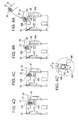
- Figs. 4 show illustrations of first examples (a) to (d) of a process until the platen bearing 22 is engaged with the engagement groove 30A.
- Fig. 4(c') is an enlarged view in which a part of the bearing 22 and the engagement groove 30A in a state of Fig. 4(c) is enlarged.
- Figs. 5 show illustrations of second examples (a) to (d) of the process until the platen bearing 22 is engaged with the engagement groove 30A.
- the bearing 22 is brought into contact with the guide wall 30B depending upon its orientation and its orientation is corrected.
- the bearing 22 is rotated clockwise and introduced into the engagement groove 30A.
- shapes of the engagement portion of the bearing and the engagement groove formed in the frame are different from those of the first embodiment.
- the engagement portion of the bearing 22 is indicated by reference symbol 22a' and the engagement groove of the frame 30 is indicated by reference symbol 30A'.
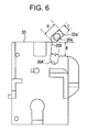
- Fig. 6 shows a side elevational view showing the respective shapes of the engagement portion 22a' of the platen bearing 22 and the engagement groove 30A' formed in the frame 30 according to the second embodiment.
- each shorter side of a rectangular shape is formed into a semicircular shape as viewed from an axial direction of the platen shaft 20a.
- This shape is a point-symmetrical shape with respect to a center of the platen shaft 20a and overlapping the original shape when the bearing 22 is rotated through 180 degrees.
- the engagement groove 30A' has substantially the same shape as that of a lower half of the above-described engagement portion 22a' so as to be engaged therewith in the case where the engagement portion 22a' is arranged longitudinally.
- a size J of the introduction port of the engagement groove 30A' is smaller than a longitudinal width H of the engagement portion 22a and is set to be somewhat larger than a lateral width I and the arcuate portion of the above-described engagement portion 22a enters and is fitted into the bottom portion of the engagement groove 30A'.
- a guide wall 30B is formed in a left shoulder portion of the engagement groove 30A' and a right shoulder portion of the engagement groove 30A' is formed to be lower by a step K.
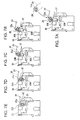
- Figs. 7 illustrate a process in which the platen bearing is engaged with the engagement groove according to the second embodiment.
- the orientation of the bearing 22 is not always kept constant. Accordingly, the bearing is brought into contact with the guide wall 30B and corrected in its orientation depending upon its orientation.
- the arcuate portion of the engagement portion 22a' of the bearing 22 is introduced while being brought into contact with a corner portion of the guide wall 30, as shown in Figs. 7(c) to 7(e), the engagement portion 22a' is rotated clockwise and corrected to the longitudinal orientation and is introduced into the introduction port of the engagement groove 30A'.
- the bearing is smoothly introduced and fitted into the engagement groove 30A under this condition. Namely, in the case where the engagement portion 22a' of the bearing 22 is introduced at any orientation, it is possible to engage the engagement portion 22a and the engagement groove 30A with each other at a normal orientation.
- the thermal printer according to the above-described first and second embodiments, it is possible to readily perform the replacement of rolls of paper or the set of the paper by the platen release mechanism for separating the platen 20 together with the bearing 22 away from the printing head, and at the same time, when the platen 20 is returned back to the normal operational position, the engagement portion 22a (22a') of the bearing 22 is engaged without any rotation to the engagement groove 30A (30A') of the frame 30. Accordingly, it is possible to solve the conventional problem that the bearing would be worn out through the rotation with respect to the frame and the printing quality would be advertently affected.
- the shape of the engagement portion 22a, 22a' of the bearing 22 is set as a point-symmetrical shape with respect to the center of the platen shaft 20a in order to cause no problem even if the bearing 22 is rotated through 180 degrees and set therein, even if the bearing 22 is held to the platen frame 24 so that it is rotatable and has a play, it is possible to smoothly engage the bearing 22 with the engagement groove 30A, 30A' in a normal orientation.
- the engagement portion 22a, 22a' is formed into a longitudinal shape, it is possible to completely avoid the retaining in a wrong orientation.
- the engagement groove 30A, 30A' is also formed into a longitudinal shape and the size of the introduction port is smaller than the longer width of the engagement portion 22a, 22a' of the bearing 22, so that it is possible to more completely avoid the retaining in a wrong direction of the engagement portion 22a, 22a' of the bearing 22.
- the guide wall 308 is brought into contact with the engagement portion 22a, 22a' of the bearing 22 to correct the bearing 22 in a normal orientation. Accordingly, it is possible to smoothly introduce the bearing 22 into the engagement groove 30A, 30A'.
- the present invention is not limited to the foregoing embodiments and various changes are possible.
- the shape is a line-symmetrical shape with respect to a straight line passing through an axial center such as a regular triangle or a regular pentagon, it is possible to ensure the effect that the bearing is not rotated.
- the engagement groove is formed into a shape following the part of the engagement portion of the bearing and the engagement portion of the bearing is fitted with almost no gap.
- the engagement portion of the bearing has a shape in which it is positioned and engaged, any shape may be taken.
- the bearings are not rotated on the engagement grooves, it is possible to prevent the degradation in durability due to the wear of the bearings and the frame, and further to stabilize the rotation of the platen to thereby make it possible to enhance the printing quality.
- the bearing is not rotated. It is thus possible to reduce the cost due to the miniaturization of the overall structure or the decrease in necessary mechanical strength of each member. Also, it is possible to reduce the rotational load of the platen to reduce the cost of the drive motor of the platen.
- the shape in which the bearing may engage with the engagement groove is similarly taken (rhombus, ellipsoid, or regular triangle or regular pentagon), it is possible to allow the bearing to be easily engaged with the engagement groove even if the bearing is held rotatably. Thus, it is possible to increase the degree of freedom of the platen release mechanism that moves while holding the bearing.
- the engagement portion of the bearing is formed into a longitudinal shape and the engagement groove is also formed into a longitudinal shape so that the engagement between the bearing and the engagement groove in a wrong orientation may be avoided.
- the contact member for correcting the orientation of the engagement portion while contacting from one side with the engagement portion of the bearing is provided in the previous stage of the engagement groove so that the bearing may always be introduced into the engagement groove smoothly and be engaged therewith normally.
Landscapes
- Handling Of Sheets (AREA)
- Common Mechanisms (AREA)
- Electronic Switches (AREA)
Abstract
Description
Claims (8)
- A thermal printer for printing on paper clamped between a printing head and a platen, comprising:wherein the engagement portion of the bearing is formed into a point-symmetrical shape with respect to a center of a platen shaft and a non-circular shape as viewed from axial direction of the platen shaft and the engagement groove is formed into a shape corresponding to the engagement portion of the bearing.a bearing for rotatably holding a shaft of the platen; a movable platen frame for holding the bearing; an engagement groove being provided on a body frame and being engageable with an engagement portion of the bearing in a state in which the platen is moved to a normal operation position; and a lock arm for retaining a part of the bearing and for fixing the bearing in engagement with the engagement groove, in which a platen release mechanism for allowing the platen to be attachable to and detachable from the normal operation position is provided,
- The thermal printer according to claim 1, wherein the engagement portion of the bearing is formed into a longitudinal shape as viewed from the axial direction of the platen shaft.
- The thermal printer according to claim 2, wherein a size of an introduction port of the engagement groove is set so as to be smaller than a longer width of the engagement portion of the bearing.
- The thermal printer according to 1, further a contact member that is brought into contact with one side of the engagement portion for correcting an orientation of the engagement portion is provided on a forward side of the engagement groove on a path along which the engagement portion of the bearing is moved.
- A thermal printer for printing on paper clamped between a printing head and a platen, comprising:wherein the engagement portion of the bearing is formed into a line-symmetrical shape with respect to a straight line passing through a center of a platen shaft and a non-circular shape as viewed from axial direction of the platen shaft and said engagement groove is formed into a shape corresponding to the engagement portion of the bearing.a bearing for rotatably holding a shaft of the platen; a movable platen frame for holding the bearing; an engagement groove being provided on a body frame and being engageable with an engagement portion of the bearing in a state in which the platen is moved to a normal operation position; and a lock arm for retaining a part of the bearing and for fixing the bearing in engagement with the engagement groove, in which a platen release mechanism for allowing said platen to be attachable to and detachable from the normal operation position is provided,
- The thermal printer according to claim 5, wherein the engagement portion of the bearing is formed into a longitudinal shape as viewed from the axial direction of the platen shaft.
- The thermal printer according to claim 6, wherein a size of an introduction port of the engagement groove is set so as to be smaller than a longer width of the engagement portion of the bearing.
- The thermal printer according to 5, further a contact member that is brought into contact with one side of the engagement portion for correcting an orientation of the engagement portion is provided on a forward side of the engagement groove on a path along which the engagement portion of the bearing is moved.
Applications Claiming Priority (2)
| Application Number | Priority Date | Filing Date | Title |
|---|---|---|---|
| JP2002046569 | 2002-02-22 | ||
| JP2002046569A JP3910465B2 (en) | 2002-02-22 | 2002-02-22 | Thermal printer |
Publications (3)
| Publication Number | Publication Date |
|---|---|
| EP1338425A2 true EP1338425A2 (en) | 2003-08-27 |
| EP1338425A3 EP1338425A3 (en) | 2004-07-07 |
| EP1338425B1 EP1338425B1 (en) | 2007-04-04 |
Family
ID=27655363
Family Applications (1)
| Application Number | Title | Priority Date | Filing Date |
|---|---|---|---|
| EP03251001A Expired - Lifetime EP1338425B1 (en) | 2002-02-22 | 2003-02-19 | Thermal printer having a platen release mechanism |
Country Status (4)
| Country | Link |
|---|---|
| US (1) | US6744457B2 (en) |
| EP (1) | EP1338425B1 (en) |
| JP (1) | JP3910465B2 (en) |
| DE (1) | DE60312907T2 (en) |
Cited By (5)
| Publication number | Priority date | Publication date | Assignee | Title |
|---|---|---|---|---|
| EP2353875A1 (en) * | 2010-02-02 | 2011-08-10 | Seiko Instruments Inc. | Printer |
| US8585305B2 (en) | 2010-02-02 | 2013-11-19 | Seiko Instruments Inc. | Printer |
| CN106079903A (en) * | 2016-08-15 | 2016-11-09 | 厦门普瑞特科技有限公司 | A kind of printer core of quick mounting or dismounting |
| CN107336531A (en) * | 2016-04-28 | 2017-11-10 | 富士通电子零件有限公司 | Print apparatus |
| EP3251861A1 (en) * | 2016-05-24 | 2017-12-06 | Fujitsu Component Limited | Printer |
Families Citing this family (17)
| Publication number | Priority date | Publication date | Assignee | Title |
|---|---|---|---|---|
| JP4343796B2 (en) * | 2004-08-24 | 2009-10-14 | セイコーインスツル株式会社 | Platen moving mechanism and thermal printer |
| JP2007331112A (en) * | 2006-06-12 | 2007-12-27 | Seiko Epson Corp | Thermal printer |
| JP6138552B2 (en) | 2013-04-01 | 2017-05-31 | 富士通コンポーネント株式会社 | Printer device and operation method of printer device |
| JP6372982B2 (en) | 2013-08-28 | 2018-08-15 | 富士通コンポーネント株式会社 | Printer device |
| JP6250333B2 (en) | 2013-08-28 | 2017-12-20 | 富士通コンポーネント株式会社 | Printer device |
| JP6293439B2 (en) | 2013-08-28 | 2018-03-14 | 富士通コンポーネント株式会社 | Printer device |
| EP3427965B1 (en) | 2014-07-23 | 2021-04-21 | Fujitsu Component Limited | Printer |
| JP6886233B2 (en) | 2015-09-09 | 2021-06-16 | 富士通コンポーネント株式会社 | Printer equipment |
| JP6534588B2 (en) | 2015-09-10 | 2019-06-26 | 富士通コンポーネント株式会社 | Printer device |
| JP6587878B2 (en) | 2015-09-18 | 2019-10-09 | 富士通コンポーネント株式会社 | Printer device |
| JP2017081128A (en) | 2015-10-30 | 2017-05-18 | 富士通コンポーネント株式会社 | Printer device |
| JP2017081129A (en) * | 2015-10-30 | 2017-05-18 | 富士通コンポーネント株式会社 | Printer device |
| JP6751309B2 (en) | 2016-05-24 | 2020-09-02 | 富士通コンポーネント株式会社 | Printer |
| JP6829008B2 (en) | 2016-05-24 | 2021-02-10 | 富士通コンポーネント株式会社 | Printer |
| JP6901246B2 (en) | 2016-08-03 | 2021-07-14 | 富士通コンポーネント株式会社 | Printer |
| CN111332036B (en) * | 2020-04-15 | 2025-05-20 | 厦门汉印股份有限公司 | Roll paper printer |
| US11904603B2 (en) | 2022-01-27 | 2024-02-20 | Zebra Technologies Corporation | Printer with tabs to secure platen roller bushing |
Family Cites Families (8)
| Publication number | Priority date | Publication date | Assignee | Title |
|---|---|---|---|---|
| JPS6368445U (en) * | 1986-10-24 | 1988-05-09 | ||
| JP2535587B2 (en) * | 1988-03-29 | 1996-09-18 | 日本トムソン株式会社 | Thin cross roller bearing |
| FR2697776B1 (en) * | 1992-11-06 | 1995-03-03 | Axiohm | Opening thermal printing device. |
| FR2737153B1 (en) * | 1995-07-28 | 1999-01-29 | Investix Sa | EVOLVING THERMAL PRINTING MECHANISM |
| US6118469A (en) * | 1995-11-21 | 2000-09-12 | Seiko Epson Corporation | Thermal printer |
| US6004053A (en) * | 1998-09-11 | 1999-12-21 | Comtec Informationsystems, Inc. | Printer apparatus |
| JP2000094767A (en) * | 1998-09-25 | 2000-04-04 | Fujitsu Takamisawa Component Ltd | Thermal printer |
| DE60002145T2 (en) * | 1999-12-15 | 2003-12-18 | Seiko Epson Corp., Tokio/Tokyo | printer |
-
2002
- 2002-02-22 JP JP2002046569A patent/JP3910465B2/en not_active Expired - Fee Related
-
2003
- 2003-02-05 US US10/358,822 patent/US6744457B2/en not_active Expired - Fee Related
- 2003-02-19 DE DE60312907T patent/DE60312907T2/en not_active Expired - Lifetime
- 2003-02-19 EP EP03251001A patent/EP1338425B1/en not_active Expired - Lifetime
Cited By (7)
| Publication number | Priority date | Publication date | Assignee | Title |
|---|---|---|---|---|
| EP2353875A1 (en) * | 2010-02-02 | 2011-08-10 | Seiko Instruments Inc. | Printer |
| US8585305B2 (en) | 2010-02-02 | 2013-11-19 | Seiko Instruments Inc. | Printer |
| CN107336531A (en) * | 2016-04-28 | 2017-11-10 | 富士通电子零件有限公司 | Print apparatus |
| EP3246170A1 (en) * | 2016-04-28 | 2017-11-22 | Fujitsu Component Limited | Printer |
| EP3251861A1 (en) * | 2016-05-24 | 2017-12-06 | Fujitsu Component Limited | Printer |
| CN106079903A (en) * | 2016-08-15 | 2016-11-09 | 厦门普瑞特科技有限公司 | A kind of printer core of quick mounting or dismounting |
| CN106079903B (en) * | 2016-08-15 | 2017-11-21 | 厦门普瑞特科技有限公司 | A kind of printer core fast assembled and disassembled |
Also Published As
| Publication number | Publication date |
|---|---|
| EP1338425A3 (en) | 2004-07-07 |
| JP3910465B2 (en) | 2007-04-25 |
| EP1338425B1 (en) | 2007-04-04 |
| DE60312907T2 (en) | 2007-12-13 |
| DE60312907D1 (en) | 2007-05-16 |
| JP2003246104A (en) | 2003-09-02 |
| US20030160857A1 (en) | 2003-08-28 |
| US6744457B2 (en) | 2004-06-01 |
Similar Documents
| Publication | Publication Date | Title |
|---|---|---|
| EP1338425B1 (en) | Thermal printer having a platen release mechanism | |
| USRE40202E1 (en) | Ink ribbon cassette for thermal transfer printer | |
| US5678936A (en) | Printer with head gap adjusting mechanism | |
| KR20210069008A (en) | Printing unit and thermal printer | |
| JP4089643B2 (en) | Image recording device | |
| US4937632A (en) | Cleaning device of image-forming apparatus | |
| EP1055623B1 (en) | Sheet feeder with lateral adjusting means | |
| EP2096058A2 (en) | Sheet conveying device and image recording apparatus | |
| US4865478A (en) | Retractable pin sheet feed mechanism | |
| JPH10114091A (en) | Thermal printer | |
| US10144603B2 (en) | Medium transportation device and recording apparatus | |
| JP4449710B2 (en) | Variable paper width printer | |
| US4212551A (en) | Ribbon cartridge | |
| JPH11322095A (en) | Sheet feeding apparatus and image forming apparatus | |
| US8287122B2 (en) | Image forming apparatus | |
| JP3874100B2 (en) | Recording device with paper support | |
| US4971467A (en) | Printer | |
| EP0286363B1 (en) | Pin tractor assembly | |
| JP3337277B2 (en) | Paper size detection device | |
| JP2026072248A (en) | Media transport device, media placement device, media processing device | |
| JPH0671962A (en) | Sheet pressing device | |
| US20070274760A1 (en) | Cartridge case | |
| JP3667277B2 (en) | Paper feeding device and image forming apparatus provided with the device | |
| JP4191916B2 (en) | Paper feeder | |
| JP2007144729A (en) | Printer |
Legal Events
| Date | Code | Title | Description |
|---|---|---|---|
| PUAI | Public reference made under article 153(3) epc to a published international application that has entered the european phase |
Free format text: ORIGINAL CODE: 0009012 |
|
| AK | Designated contracting states |
Designated state(s): AT BE BG CH CY CZ DE DK EE ES FI FR GB GR HU IE IT LI LU MC NL PT SE SI SK TR |
|
| AX | Request for extension of the european patent |
Extension state: AL LT LV MK RO |
|
| PUAL | Search report despatched |
Free format text: ORIGINAL CODE: 0009013 |
|
| AK | Designated contracting states |
Kind code of ref document: A3 Designated state(s): AT BE BG CH CY CZ DE DK EE ES FI FR GB GR HU IE IT LI LU MC NL PT SE SI SK TR |
|
| AX | Request for extension of the european patent |
Extension state: AL LT LV MK RO |
|
| RIC1 | Information provided on ipc code assigned before grant |
Ipc: 7B 41J 11/24 B Ipc: 7B 41J 11/04 B Ipc: 7B 41J 15/04 A |
|
| 17P | Request for examination filed |
Effective date: 20041209 |
|
| AKX | Designation fees paid |
Designated state(s): DE FR IT |
|
| RAP1 | Party data changed (applicant data changed or rights of an application transferred) |
Owner name: SEIKO INSTRUMENTS INC. |
|
| GRAP | Despatch of communication of intention to grant a patent |
Free format text: ORIGINAL CODE: EPIDOSNIGR1 |
|
| GRAS | Grant fee paid |
Free format text: ORIGINAL CODE: EPIDOSNIGR3 |
|
| RIN1 | Information on inventor provided before grant (corrected) |
Inventor name: SEINO, TAKUMI Inventor name: JIMBO, SEIICHI |
|
| GRAA | (expected) grant |
Free format text: ORIGINAL CODE: 0009210 |
|
| AK | Designated contracting states |
Kind code of ref document: B1 Designated state(s): DE FR IT |
|
| RIN1 | Information on inventor provided before grant (corrected) |
Inventor name: JIMBOI, SEIICHI Inventor name: SEINO, TAKUMI |
|
| REF | Corresponds to: |
Ref document number: 60312907 Country of ref document: DE Date of ref document: 20070516 Kind code of ref document: P |
|
| ET | Fr: translation filed | ||
| PLBE | No opposition filed within time limit |
Free format text: ORIGINAL CODE: 0009261 |
|
| STAA | Information on the status of an ep patent application or granted ep patent |
Free format text: STATUS: NO OPPOSITION FILED WITHIN TIME LIMIT |
|
| 26N | No opposition filed |
Effective date: 20080107 |
|
| PGFP | Annual fee paid to national office [announced via postgrant information from national office to epo] |
Ref country code: DE Payment date: 20110216 Year of fee payment: 9 Ref country code: IT Payment date: 20110216 Year of fee payment: 9 Ref country code: FR Payment date: 20110218 Year of fee payment: 9 |
|
| REG | Reference to a national code |
Ref country code: FR Ref legal event code: ST Effective date: 20121031 |
|
| PG25 | Lapsed in a contracting state [announced via postgrant information from national office to epo] |
Ref country code: IT Free format text: LAPSE BECAUSE OF NON-PAYMENT OF DUE FEES Effective date: 20120219 |
|
| REG | Reference to a national code |
Ref country code: DE Ref legal event code: R119 Ref document number: 60312907 Country of ref document: DE Effective date: 20120901 |
|
| PG25 | Lapsed in a contracting state [announced via postgrant information from national office to epo] |
Ref country code: FR Free format text: LAPSE BECAUSE OF NON-PAYMENT OF DUE FEES Effective date: 20120229 |
|
| PG25 | Lapsed in a contracting state [announced via postgrant information from national office to epo] |
Ref country code: DE Free format text: LAPSE BECAUSE OF NON-PAYMENT OF DUE FEES Effective date: 20120901 |