-
This application is a continuation-in-part of pending U.S. Patent application Serial
No. 09/483,914 filed on January 18, 2000.
Background of the Invention
-
The subject invention relates to a catheter and introducer needle assembly that
includes a needle shield that will safely shield the sharp distal tip of the introducer
needle after the needle has been used to insert the catheter into a patient.
-
Catheters, particularly intravenous (IV) catheters, are used for infusing fluid, such
as normal saline solution, various medicaments and total parenteral nutrition, into a
patient or withdrawing blood from a patient. Peripheral IV catheters tend to be relatively
short, and are on the order of about one and one-half inches in length. The most
common type of IV catheter is an over the needle peripheral IV catheter. As its name
implies, an over the needle catheter is mounted over an introducer needle having a
sharp distal tip. The catheter and the introducer needle are assembled so that the distal
tip of the introducer needle extends beyond the distal tip of the catheter with the bevel of
the needle facing up away from the patient's skin.
-
The catheter and introducer needle assembly is inserted at a shallow angle
through the patient's skin into a peripheral blood vessel. These are smaller blood
vessels that are not connected directly to the heart but are the branches of the central
blood vessels that are directly connected to the heart. In order to verify proper
placement of the assembly in the blood vessel, the clinician confirms that there is
flashback of blood in the needle and in a flashback chamber located at the proximal end
of the needle. The flashback chamber is typically formed as part of the needle hub.
Once proper placement is confirmed, the clinician applies pressure to the blood vessel
by pressing down on the patient's skin over the distal tip of the introducer needle and
the catheter. This finger pressure occludes further blood flow through the introducer
needle. The clinician withdraws the introducer needle, leaving the catheter in place,
and attaches a fluid-handling device to the catheter hub.
-
Clinicians typically use a specific technique when inserting over the needle
catheters into a patient. This technique varies depending on whether a ported over the
needle catheter or a straight over the needle catheter is used. A ported catheter
includes a radially extending side port integral with the catheter hub. In a ported
catheter, the fluid-handling device is connected to the side port. Such ported catheters
are typically used in Europe. A straight catheter does not include a side port so that the
fluid-handling device is connected to the proximal end of the catheter hub. Such
straight catheters are typically used in the United States.
-
Once the introducer needle is withdrawn from the catheter, it is a "blood
contaminated sharp" and must be properly handled. In recent years, there has been
great concern over the contamination of clinicians with a patient's blood and a
recognition that "blood contaminated sharps" must be immediately disposed. This
concern has arisen because of the advent of currently incurable and fatal diseases,
such as Acquired Immunosuppressive Deficiency Syndrome ("AIDS") and hepatitis,
which can be transmitted by the exchange of body fluids from an infected person to
another person. Thus, contact with the body fluid of an AIDS or hepatitis infected
person must be avoided to prevent the transmission of such diseases to a healthy
person. As noted above, if an introducer needle has been used to place a catheter in
the vein of an AIDS or hepatitis infected person, the introducer needle is a vehicle for
the transmission of the disease. Although clinicians are aware of the need to properly
handle "blood contaminated sharps", unfortunately in certain medical environments,
such as emergency situations or as a result of inattention or neglect, needlesticks with
contaminated introducer needles still occur.
-
As a result of the problem of accidental needlesticks by "blood contaminated
sharps", various needle shields have been developed. Generally, such needle shields
work for their intended purpose but could be improved. For example, some needle
shields are bulky, difficult to use or require special features or techniques to be
operative or are ergonomically uncomfortable for the clinician to use. In addition, some
needle shields cannot be used with both ported and straight catheters or would require
a significant change in technique by the clinician in order to be used in both ported and
straight catheters. Furthermore, certain needle shields prevent access through the
introducer needle to the blood vessel during venipuncture.
Summary of the Invention
-
It is therefore an object of this invention to provide a needle shield that is
compact.
-
It is another object of this invention to provide a needle shield that is simple and
easy to use.
-
It is still another object of this invention to provide a needle shield that requires
no special features or technique to be operative.
-
It is yet another object of this invention to provide a needle shield that is
ergonomically comfortable for the clinician to use.
-
It is a further object of this invention to provide a needle shield that can be used
with both ported and straight catheters so that the clinician does not need to change her
insertion technique.
-
It is yet a further object of this invention to provide a needle shield that will allow
access through the introducer needle to the blood vessel during venipuncture.
-
The catheter and introducer needle assembly with the needle shield and tether of
this invention includes a catheter having a distal end and a proximal end connected to
the distal end of a catheter hub. The introducer needle has a sharp distal tip and a
proximal end connected to the distal end of a needle hub. A flashback chamber is
defined in the needle hub. A vented plug may be located in the open proximal end of
the flashback chamber to allow air to escape from the flashback chamber when blood
enters the flashback chamber from the introducer needle. When the vented plug is
removed during venipuncture, the clinician can gain access to the blood vessel through
the introducer needle. The catheter is coaxially disposed over the introducer needle so
the sharp distal tip of the introducer needle is distal of the distal end of the catheter.
-
The needle shield is located substantially between the catheter and the needle
hub and defines a longitudinally extending passage through which the introducer needle
extends. The needle shield may include some barrier or other mechanism that prevents
the sharp distal tip of the needle from being moved distally with respect to the needle
shield after the sharp distal tip of the needle has been withdrawn into the needle shield.
This prevents the sharp distal tip of the needle from being reexposed once it has been
withdrawn into the needle shield.
-
The needle shield is connected to the needle hub by a tether that prevents the
needle shield from being moved distally past the sharp distal tip of the needle once the
needle has been proximally withdrawn into the needle shield. The combination of the
barrier or other mechanism associated with the needle shield and the tether prevents
distal movement of the needle with respect to the needle shield. This ensures that the
sharp distal tip of the needle remains trapped in the needle shield after the needle has
been withdrawn proximally into the needle shield after use.
-
The tether is folded over itself to form a plurality of pleats like an accordion.
Each pleat or fold defines a central opening therein to allow the needle to extend
through each pleat or fold no matter whether the tether is completely extended or
completely folded with the needle shield adjacent to the needle hub. Because the tether
can be folded into a small space so it is located between the needle shield and the
needle hub, the overall device is compact. This makes the overall device easier to
control by the clinician. In addition, the pleated configuration of the tether allows the
clinician to better control the action of the needle shield. The tether is connected to the
needle hub and the needle shield by a variety of mechanisms, such as by an adhesive,
by heat-sealing or by mechanical engagement.
Brief Description of the Drawings
-
The preferred embodiments are illustrated in the drawings in which like reference
numerals refer to like elements and in which:
- FIG. 1 is a perspective view of a ported catheter and introducer needle assembly
with the needle shield and tether of this invention prior to use;
- FIG. 2 is a perspective view of a ported catheter and introducer needle assembly
with the needle shield and tether of this invention after the needle has been withdrawn
from the catheter into the needle shield and the needle shield has been removed from
the catheter hub;
- FIG. 3 is a top plan view of a ported catheter and introducer needle assembly
with the needle shield and tether of this invention prior to use;
- FIG. 4 is a top plan view of a ported catheter and introducer needle assembly
with the needle shield and tether of this invention after the needle has been withdrawn
from the catheter into the needle shield and the needle shield has been removed from
the catheter hub;
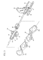
- FIG. 5 is an exploded bottom perspective view in partial cross section and
partially in phantom of a portion of the needle shield, tether and the needle hub
illustrating one method of connecting the tether to the needle shield and the needle hub;
- FIG. 6 is a bottom perspective view in partial cross section and partially in
phantom of a portion of the needle shield, tether and the needle hub illustrating one
method of connecting the tether to the needle shield and the needle hub;
- FIG. 7 is a cross sectional view of a portion of the introducer needle assembly
showing the needle shield and tether prior to use and attached to a catheter hub;
- FIG. 8 is a cross sectional view of a portion of the introducer needle assembly
showing the needle shield and tether after the sharp distal tip of the introducer needle
has been withdrawn into the needle shield and the needle shield has been removed
from the catheter hub;
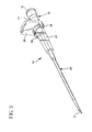
- FIG. 9 is a perspective view of a straight catheter and introducer needle
assembly with the needle shield and tether of this invention prior to use;
- FIG. 10 is a bottom perspective view of the needle shield, tether and the needle
hub where the needle shield is adjacent to the needle hub illustrating a second method
of connecting the tether to the needle hub with the proximal most pleat of the tether
disengaged from the needle hub;
- FIG. 11 is a bottom perspective view of the needle shield, tether and the needle
hub where the needle shield is adjacent to the needle hub illustrating a second method
of connecting the tether to the needle hub with the proximal most pleat of the tether
engaged with the needle hub; and
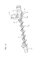
- FIG. 12 is a bottom perspective view of introducer needle assembly with
the needle shield and tether of this invention after the needle has been withdrawn from
the catheter into the needle shield and the needle shield has been removed from the
catheter hub illustrating a second method of connecting the tether to the needle hub.
-
Detailed Description of the Invention
-
As used herein, the term "proximal" refers to a location on the catheter and
introducer needle assembly with the needle shield and tether of this invention that is
closest to the clinician using the device and farthest from the patient in connection with
whom the device is used when the device is used in its normal operation. Conversely,
the term "distal" refers to a location on the catheter and introducer needle assembly with
the needle shield and tether of this invention that is farthest from the clinician using the
device and closest to the patient in connection with whom the device is used when the
device is used in its normal operation.
-
The catheter and introducer needle assembly of this invention is identified
generally by the numeral 10. It includes a catheter assembly 20 and an introducer
needle assembly 30 that includes a needle shield 40 and a tether 44.
-
Catheter assembly 20 includes a catheter 21 that has a proximal end and a distal
ends A catheter hub 24 is affixed to the proximal end of catheter 21. Suitable materials
for catheter 21 include, but are not limited to, thermoplastic resins such as
polytetrafluoroethylene (PTFE), fluorinated ethylene propylene copolymer (FEP),
polyurethane and the like. Preferably, catheter 21 is formed from thermoplastic
hydrophilic polyurethane that softens with exposure to physiological conditions present
in the patient's body. Suitable materials for catheter hub 24 include, but are not limited
to, thermoplastic polymeric resins such as polycarbonate, polystyrene, polypropylene
and the like.
-
Catheter hub 24 may include a radially outwardly extending side port 25, which is
useful for connecting a fluid handling device to catheter 21 for infusing fluids into the
patient's blood vessel. See FIG. 1. Preferably, side port 25 extends upwardly away
from the patient when catheter 21 is inserted into the patient. In addition, a pair of
wings 26 may be attached to or integrally formed with catheter hub 24. Wings 26 are
useful to stabilize catheter 21 in the patient and provide a surface that facilitates taping
of catheter assembly 20 to the patient to fix catheter 21 properly in the patient's
vasculature.
-
Although, the majority of the description of catheter and introducer needle
assembly 10 of this invention is directed to a catheter having a side port, it is to be
understood that this invention can also be used with a straight catheter. See for
example, FIG. 9.
-
A cover 27 may be used to cover catheter 21 and the introducer needle 31 prior
to use. Preferably cover 27 is formed from a hard polymeric material such as
thermoplastic polymeric resins, which include polycarbonate, polystyrene,
polypropylene and the like. Of course other materials may also be used for cover 27.
-
Introducer needle assembly 30 includes introducer needle 31 having a sharp
distal tip defined by a bevel. The proximal end of introducer needle 31 is connected to a
needle hub 34. Introducer needle 31 is preferably formed from stainless steel. Needle
hub 34 can include an integrated flashback chamber having an open proximal end.
Needle hub 34 is preferably formed from the same types of materials that are used to
form catheter hub 24. Preferably, the open proximal end of needle hub 34 is closed to
fluid flow by a vented plug 35 which allows air but not fluid to flow therethrough. This
facilitates blood flow into the flashback chamber but prevents blood from leaking out.
-
Vented plug 35 may be removably connected to the open proximal end of needle
hub 34. This allows a clinician to gain access to the patient's blood vessel during
venipuncture. In this way, a syringe could be attached to the open proximal end of
needle hub 34 for aspiration during insertion of catheter and introducer needle assembly
10.
-
Needle hub 34 may also include a radially extending tab 36, which may be
grasped in combination with side port 25 to facilitate insertion of assembly 10 into the
patient. Tab 36 may also be useful for withdrawing introducer needle 31 from catheter
21 after catheter 21 has been properly located in the patient's vasculature.
-
In addition, needle hub 34 may include a pair of longitudinally extending fingers
39. These fingers 39 frictionally engage needle shield 40. In this way, needle hub 34 is
held in place adjacent to catheter hub 24 so that the sharp distal tip of introducer needle
31 extends distally of the distal end of catheter 21. The proximally directed force
needed to overcome the frictional engagement between fingers 39 and needle shield 40
is less than the proximally directed force needed to overcome the removable connection
between needle shield 40 and catheter hub 24.
-
As noted above, introducer needle assembly 30 also includes needle shield 40.
Like catheter hub 24 and needle hub 34, suitable materials for needle shield 40 include,
but are not limited to, thermoplastic polymeric resins such as polycarbonate,
polystyrene, polypropylene and the like. Needle shield 40 includes main body portion
41, which defines a longitudinally extending passage 42 therethrough. Longitudinally
extending passage 42 allows introducer needle 31 to extend longitudinally through main
body portion 41. The diameter of longitudinally extending passage 42 is slightly larger
than the diameter of the main portion of introducer needle 31. This allows the main
portion of introducer needle 31 to easily pass through longitudinally extending passage
42.
-
An annular lip 43 is located along the distal portion of longitudinally extending
passage 42. Preferably, lip 43 is integrally formed with needle shield 40 and contacts
the main portion of introducer needle 31. In this way, lip 43 acts as a fluid seal along
the main portion of introducer needle 31. During venipuncture, blood flow between
introducer needle 31 and needle shield 40 is minimized to minimize blood leakage from
the device.
-
A transverse barrier 49 located in needle shield 40 to act as a barrier to
reexposure of the sharp distal tip of introducer needle 31 after it has been withdrawn
into main body portion 41. Transverse barrier 49 is preferably formed as an integral
member from a resilient metal, such as stainless steel. Preferably, transverse barrier is
formed as a generally cylindrical main body portion 49b with two lips 49a in the
configuration of a duckbill extending generally proximally from the distal end of main
body portion 49b. The longitudinal dimension of main body portion 49b and lips 49a
can be any value but preferably, main body portion 49b is longer than lips 49a. This
relationship facilitates the manufacture of this device and makes for a more robust
design.
-
Prior to use, lips 49a extend toward the proximal end of introducer needle 31 and
generally parallel to the main body portion of introducer needle 31. See FIG. 7. After
proper placement of catheter 21 into a patient's blood vessel, lips 49a ride along the
main body portion of introducer needle 31 when introducer needle 31 is being
withdrawn from catheter 21. Once the sharp distal tip of introducer needle 31 is
withdrawn to a position proximal of lips 49a, the resilient nature of lips 49a causes them
to return to a position that is transverse to introducer needle 31. The configuration of
lips 49a as shown in FIG. 8 prevents reexposure of the sharp distal tip that could occur
if introducer needle 31 were thereafter moved distally with respect to needle shield 40.
See FIG. 8.
-
Other types of transverse barriers could also be used. For example, a transverse
barrier having a single arm could be used in place of the pair of lips 49a forming a
duckbill as described above.
-
Main body portion 41 also includes a plurality of longitudinally extending fingers
47. Fingers 47 engage catheter hub 24 to hold introducer needle assembly 30 together
with catheter assembly 20. Thus, as needle hub 34 is moved proximally with respect to
catheter hub 24, needle shield 40 remains adjacent to catheter hub 24. As described in
more detail below, tether 44 has a length that maintains the sharp distal tip of introducer
needle 31 in main body portion 41 of needle shield when tether 44 is fully extended.
Thus, once the sharp distal tip of introducer needle 31 is moved into main body portion
41 of needle shield 40, any additional proximally directed movement applied to needle
hub 24 will overcome the friction force between fingers 47 and catheter hub 24. In this
way, needle shield 40 can be removed from catheter hub 24. If desired, main body
portion 41 may be configured so that the exterior surface of the distal portion of main
body portion 41 frictionally engages the interior surface of catheter hub 24 to help hold
needle shield 40 with catheter hub 24.
-
Fingers 47 may also include radially inwardly directed projections 48. Projections
48 are sized to mechanically engage catheter hub 24 by a snap fit. If projections 48 are
used, the force needed to remove main body portion 41 from catheter hub 24 may be
more precisely controlled than if only fingers 47 or a friction fit are used. Once the
proper proximally directed force is applied to main body portion 41, projections 48
override catheter hub 24 and main body portion 41 can be removed from catheter hub
24. Again, tether 44 maintains main body portion 41 in the proper location so that the
sharp distal tip of introducer needle 31 is safely located within main body portion 41 of
needle shield 40.
-
Tether 44 has a length that is comparable to the exposed length of introducer
needle 31. This length maintains the sharp distal tip of introducer needle 31 in main
body portion 41 of needle shield 40 when tether 44 is fully extended. Tether 44 is
folded over itself to form a plurality of pleats 44a like an accordion. Each pleat 44a
defines a central opening 45 therein to allow introducer needle 31 to extend through
each pleat 44a whether tether 44 is completely extended, see FIG. 4, or completely
folded with main body portion 41 of needle shield 40 adjacent to needle hub 34, see
FIG. 3. By forming tether 44 in this way, a compact design is achieved for catheter and
introducer needle assembly 10.
-
Tether 44 can be made of any relatively stiff yet flexible material. However,
polyethylene terephthalate (PET) is the preferred material. One benefit of using PET is
that it is relatively stiff so that when it is folded into a pleated or an accordion-like
configuration, it provides a slight biasing force to help maintain tether 44 in the
completely extended position. This in turn aids in maintaining needle shield 40 in
position over the sharp distal tip of introducer needle 31.
-
Tether 44 can be connected to needle hub 34 and needle shield 40 by any
standard means, such as by an adhesive or by heat-sealing. Preferably, tether 44 is
connected to needle hub 34 and needle shield 4o through mechanical engagement as
well as by an adhesive. For example, a slot 37 may be formed along a distal portion of
needle hub 34 where one end of tether 44 can be placed. Slot 37 thus provides an
edge along which a proximal pleat 44b of tether 44 can mechanically engage needle
hub 34 to prevent tether 44 from being removed from needle hub 34 during use. See
FIGS. 5 and 6. Alternatively, a radially extending button 32 defining a slot 33 therein
can be formed along a bottom portion of needle hub 34. One end of tether 44 can be
located about button 32 so that slot 33 provides an edge along which a proximal pleat
44b can mechanically engage needle hub 34. See FIGS. 10-12. As to main body
portion 41, a distal pleat 44c can be looped around main body portion 41 of needle
shield 40 to prevent tether 44 from being removed from main body portion 41 during
use. See FIGS. 5 and 6. Although it is preferred to have tether 44 connected to needle
hub 34 and needle shield 40 as described above, it is to be understood that other well
known methods for joining two pieces together may be used.
-
The combination of the material for tether 44, the pleated configuration of tether
44, and the specific connection of distal pleat 44c to main body portion 41 causes the
longitudinal axis of main body portion 41 to form an oblique angle with respect to
introducer needle 31 when tether 44 is fully extended. This helps to ensure that the
sharp distal tip of introducer needle 31 remains trapped inside needle shield 40 if
introducer needle 31 were to subsequently be moved distally with respect to main body
portion 41 and prevents the sharp distal tip of introducer needle 31 from being
reexposed after use.
-
In order to place catheter 21 into a patient's blood vessel, the clinician
substantially longitudinally aligns introducer needle 31 and catheter 21 with the target
blood vessel. The bevel defining the sharp distal tip of introducer needle 31 should be
facing substantially away from the skin surface during venipuncture. The clinician
inserts introducer needle 31 and catheter 21 at a shallow angle, preferably less than
about 35 degrees, into the skin so that the sharp distal tip of introducer needle 31 enters
the target blood vessel. The clinician then preferably observes a blood flashback in the
flashback chamber.
-
After confirming placement of introducer needle 31 and catheter 21 in the target
blood vessel, the clinician advances catheter 21 distally axially along introducer needle
31 into position in the blood vessel. After proper placement of catheter 21 is achieved,
the clinician places a finger from her other hand on the patient's skin over the blood
vessel distal of distal end of catheter 21 and the sharp distal tip of introducer needle 31.
By placing her finger on the patient's skin and applying sufficient pressure on the skin,
the clinician thereby minimizes blood flow through catheter 21. The clinician then
withdraws introducer needle 31 from catheter 21 by pulling needle hub 34 in a proximal
direction. Once sharp distal tip of introducer needle 31 is located within main body
portion 41 of needle shield 40, continued proximal movement of needle hub 34 will
result in a force sufficient to overcome the force holding fingers 47 to catheter hub 24 so
that main body portion 41 can be removed from catheter hub 24. Thereafter, the
clinician may attach any desired fluid-handling device to side port 25, if a ported
catheter is used, or to catheter hub 24, if a straight catheter is used, and commence the
planned treatment. Main body portion 41 of needle shield 40 with the sharp distal tip of
introducer needle 31 shielded therein may then be disposed of according to the facility's
disposal protocol.
-
Thus, it is seen that a catheter and introducer needle assembly with a needle
shield and tether is provided that is compact, simple and easy to use, that requires no
special features or technique to be operative, that is ergonomically comfortable for the
clinician to use, that can be used with both ported and straight catheters without any
change in technique by the clinician, and that allows access through the introducer
needle to the blood vessel during venipuncture.