EP1337811B1 - Multiphase flow meter using multiple pressure differentials - Google Patents
Multiphase flow meter using multiple pressure differentials Download PDFInfo
- Publication number
- EP1337811B1 EP1337811B1 EP01998161A EP01998161A EP1337811B1 EP 1337811 B1 EP1337811 B1 EP 1337811B1 EP 01998161 A EP01998161 A EP 01998161A EP 01998161 A EP01998161 A EP 01998161A EP 1337811 B1 EP1337811 B1 EP 1337811B1
- Authority
- EP
- European Patent Office
- Prior art keywords
- pressure
- location
- conduit
- measuring
- flow meter
- Prior art date
- Legal status (The legal status is an assumption and is not a legal conclusion. Google has not performed a legal analysis and makes no representation as to the accuracy of the status listed.)
- Expired - Lifetime
Links
- 239000012530 fluid Substances 0.000 claims abstract description 37
- 239000012223 aqueous fraction Substances 0.000 claims abstract description 29
- XLYOFNOQVPJJNP-UHFFFAOYSA-N water Substances O XLYOFNOQVPJJNP-UHFFFAOYSA-N 0.000 claims abstract description 27
- 238000000034 method Methods 0.000 claims abstract description 14
- 238000011144 upstream manufacturing Methods 0.000 claims abstract description 11
- 238000005259 measurement Methods 0.000 claims description 13
- 230000008569 process Effects 0.000 claims description 2
- 229930195733 hydrocarbon Natural products 0.000 description 8
- 150000002430 hydrocarbons Chemical class 0.000 description 8
- 239000004215 Carbon black (E152) Substances 0.000 description 7
- 230000008901 benefit Effects 0.000 description 5
- 230000002285 radioactive effect Effects 0.000 description 4
- 239000000203 mixture Substances 0.000 description 3
- RXZBMPWDPOLZGW-HEWSMUCTSA-N (Z)-roxithromycin Chemical compound O([C@@H]1[C@@H](C)C(=O)O[C@@H]([C@@]([C@H](O)[C@@H](C)C(=N\OCOCCOC)/[C@H](C)C[C@@](C)(O)[C@H](O[C@H]2[C@@H]([C@H](C[C@@H](C)O2)N(C)C)O)[C@H]1C)(C)O)CC)[C@H]1C[C@@](C)(OC)[C@@H](O)[C@H](C)O1 RXZBMPWDPOLZGW-HEWSMUCTSA-N 0.000 description 2
- 230000008859 change Effects 0.000 description 2
- 238000011065 in-situ storage Methods 0.000 description 2
- 238000004519 manufacturing process Methods 0.000 description 2
- FAPWRFPIFSIZLT-UHFFFAOYSA-M Sodium chloride Chemical compound [Na+].[Cl-] FAPWRFPIFSIZLT-UHFFFAOYSA-M 0.000 description 1
- 238000009529 body temperature measurement Methods 0.000 description 1
- 238000001739 density measurement Methods 0.000 description 1
- 230000009977 dual effect Effects 0.000 description 1
- 230000036541 health Effects 0.000 description 1
- 230000001939 inductive effect Effects 0.000 description 1
- 238000000691 measurement method Methods 0.000 description 1
- 230000007246 mechanism Effects 0.000 description 1
- 230000004048 modification Effects 0.000 description 1
- 238000012986 modification Methods 0.000 description 1
- 239000003129 oil well Substances 0.000 description 1
- 238000004806 packaging method and process Methods 0.000 description 1
- 238000010079 rubber tapping Methods 0.000 description 1
- 239000011780 sodium chloride Substances 0.000 description 1
- 239000000126 substance Substances 0.000 description 1
- 239000011800 void material Substances 0.000 description 1
Images

Classifications
-
- G—PHYSICS
- G01—MEASURING; TESTING
- G01F—MEASURING VOLUME, VOLUME FLOW, MASS FLOW OR LIQUID LEVEL; METERING BY VOLUME
- G01F1/00—Measuring the volume flow or mass flow of fluid or fluent solid material wherein the fluid passes through a meter in a continuous flow
- G01F1/05—Measuring the volume flow or mass flow of fluid or fluent solid material wherein the fluid passes through a meter in a continuous flow by using mechanical effects
- G01F1/34—Measuring the volume flow or mass flow of fluid or fluent solid material wherein the fluid passes through a meter in a continuous flow by using mechanical effects by measuring pressure or differential pressure
- G01F1/36—Measuring the volume flow or mass flow of fluid or fluent solid material wherein the fluid passes through a meter in a continuous flow by using mechanical effects by measuring pressure or differential pressure the pressure or differential pressure being created by the use of flow constriction
- G01F1/40—Details of construction of the flow constriction devices
- G01F1/44—Venturi tubes
-
- G—PHYSICS
- G01—MEASURING; TESTING
- G01F—MEASURING VOLUME, VOLUME FLOW, MASS FLOW OR LIQUID LEVEL; METERING BY VOLUME
- G01F1/00—Measuring the volume flow or mass flow of fluid or fluent solid material wherein the fluid passes through a meter in a continuous flow
- G01F1/74—Devices for measuring flow of a fluid or flow of a fluent solid material in suspension in another fluid
Definitions
- the present invention relates to apparatus for, and a method of, measuring the flow of a multi-phase fluid.
- the invention is particularly, but not exclusively, suitable for measuring the flow of multi-phase fluids produced from oil and gas wells.
- Multi-phase metering systems are widely used in the oil and gas and petrochemical industries. In the oil and gas industry it is necessary to measure the flow rates of oil, gas and water, all of which are produced from the sub-surface reservoir to surface via "production wells" drilled in the earth.
- two-phase hydrocarbon/water flow metering is achieved by the use of a volume fraction determining device in addition to a venturi.
- the fraction measurement device for hydrocarbon/water usually, but not always, takes advantage of differing electro-magnetic properties of the two phases to determine the volumetric phase fractions.
- Existing downhole water fraction meters allow the metering of the two-phase fractions (oil-water or gas-water) over the whole of the water fraction range from 0 to 1 - for example, roxar MF1 water cut meter (Roxar, Norway), Fluenta MPFM 1900 (Fluenta, Norway). It is also known that it is possible to measure the gas fraction, otherwise known as the void fraction, by the use of radio-active density measurement devices.
- radio-active sources have two principal disadvantages. Firstly, the sources require careful and substantial packaging to mitigate the health and safety implications of using such sources and, secondly, the use of such sources currently installed in oil and gas wells is still not an accepted practice throughout the oil and gas industry.
- EP0684458 describes a device for measuring flow rate of multiphase fluids such as oil well effluents containing hydrocarbons, gas and water.
- the device comprises first and second sections each including a passage provided with means for inducing a change of speed and means for measuring the resulting pressure differences.
- WO95/02165 describes an apparatus and method for measuring flow rate which allows measurement of the flow rate of separate phases of a multiphase fluid.
- two flow metres are disposed in series, separated by a choke or orifice plate.
- An object of the present invention is to provide an improved apparatus and method for measuring the flow and multi-phase fluids, particularly from production wells.
- the present invention solves the problems associated with such radio-active sources by eliminating the need for such sources to measure the gas fraction, by taking advantage of the high compressibility of the gas phase, as disclosed in US Patent No. 4,168,624 .
- said water fraction measuring means has a capacitance sensor for calculating a water fraction of an oil-continuous fluid flowing in said conduit and a conductance sensor for calculating the conductivity of a water-continuous fluid flowing in said conduit.
- said water fraction measuring means includes a microwave generator and detector for detecting the water fraction of fluid flowing in said conduit.
- the first and second venturi, the pressure drop creation means and the water fraction measuring means are disposed in a single tubular member.
- first and the second venturi, the pressure drop creation means and the water fraction measuring means are disposed over a plurality of tubular members.
- the method includes the step of measuring the water fraction upstream of the first location.
- Fig. 1 of the drawings depicts a standard venturi meter 10 which measures the total mass flow rate in a conduit 12 by measuring the pressure drop ⁇ P caused by the restriction throat 14.
- the fluid fractions are known, along with the densities of the fluids, at the in situ fluid flow pressure and temperature P 1 , T 1 , then both the individual phase mass flow rates and the individual volumetric flow rates can be determined, as is well known in the art and as is disclosed in Flow Measurement Engineering Handbook, Miller, R.W. McGraw-Hill 1996 ; Venturi Meters in Multi-Phase Flow, National Engineering Laboratory (UK), Report No. 286/99, 1999 .
- Fig. 2 of the drawings depicts a multi-phase flowmeter in accordance with the first and preferred embodiment of the present invention.
- the multi-phase flowmeter is disposed in a single conduit 22 along which well fluid flows in the direction of arrow A.
- Conduit end 22a is the upstream end and 22b is the downstream end.
- the multi-phase flowmeter 20 consists of a water fraction meter 23, a first venturi 24 disposed at a first location downstream of the water fraction meter, and a second venturi 26 spaced along the conduit 22 from venturi 24.
- the second venturi 26 is a double venturi.
- a first venturi portion 26a is used to generate a pressure loss and a second venturi portion 26b with a narrower throat is used to measure a pressure differential for use in multi-phase flow calculations, as will be later described. Disposing these components in a single conduit 20 provides a compact flowmeter structure without any moving parts.
- the diameter of the conduit 20 is known and the venturi 24 has a first throat restriction d 1 so that a pressure differential ⁇ P 1 is measured at venturi 24.
- pressure differential ⁇ P 2 is measured between the throat restriction D2 of venturi 26a and the throat d 2 of venturi 26b.
- a pressure differential ⁇ P is measured across venturi 26a, between the diameter D 1 and diameter D 2 of venturi 26a.
- the absolute pressure and temperature of the fluid is measured upstream of venturi 24 at location 27.
- M 1 Total mass/s at (1)
- M 2 Total mass/s at (2)
- M 01 mass/s oil at (1)
- M 02 mass/s oil at (2)
- M G1 mass/s gas at (1)
- M G2 mass/s gas at (2)
- M W1 mass/s water at (1)
- M W2 mass/s water at (2)
- ⁇ 01 de nsity of oil at (1)
- ⁇ 02 density of oil at (2)
- ⁇ G1 density of gas at (1)
- ⁇ G2 density of gas at (2)
- ⁇ W1 density of water at (1)
- ⁇ W2 density of water at (2)
- V 01 volume/s of oil at (1)
- V 02 volume/s of oil at (2)
- V W1 volume/s of water at (1)
- V W2 volume/s of water at (2)
- V G1 volume/s of gas at (1)
- V G2 volume/s of gas at (2)
- P 1 T 1 is the pressure, temperature upstream of venturi 24.
- P 2 T 2 is the pressure, temperature upstream of venturi 26b.
- ⁇ P is the pressure differential between the upstream tappings of venturis 24,26b.
- ⁇ P 1 is the pressure loss across venturi 24.
- ⁇ P 2 is the pressure loss across venturi 26b.
- V 2 and V 1 are both unknown.
- V 2 can be expressed as a function of V 1 provided that the pressure volume and temperature relationships (PVT) of the gas and oil are known. The water is assumed to remain unchanged from location 1 to location 2.
- PVT pressure volume and temperature relationships
- V q ⁇ 2 [ V q ⁇ 1 * C q x ⁇ P + ⁇ R S * V 01 ⁇ rs is the volume of gas liberated per unit of volume of oil at P 1 T 1 over the pressure ⁇ P
- V q1 * C q * ⁇ P is the volumetric expansion from point 1 to point 2
- One sensor 30a measures the effective permittivity when the oil or gas forms a continuous phase, that is the bulk of the fluid mixture is insulating.
- a second sensor 30b measures the effective resistivity when the water forms a continuous phase and the mixture is conducting.
- Equation 5 The calculations down to equation 5 are then made and in the first iteration the water volume fraction is calculated from the water fraction meter using the capacitance sensor. Assuming no gas is present, then the permittivity of the hydrocarbon is equal to the permittivity of the oil.
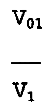
- volume fractions of the water and gas fractions are estimated, allowing V 01 V 1 the oil volume fractions to be calculated.
- V W ⁇ 1 qV 1 Total * V W ⁇ 1 V 1
- V 01 qV 1 Total * V 01 V 1
- V G ⁇ 1 qV 1 Total * V G ⁇ 1 V 1
- Fig. 3 of the drawings depicts a multi-flowmeter.
- the flowmeter comprises a water fraction meter 40 upstream of a first venturi 42.
- a second downstream venturi 44 spaced from the first venturi and between the venturis 42,44 is a pressure drop device or choke 46.
- the same calculations applied to the first embodiment can be similarly applied here to provide the same output results.
- FIG. 4 of the drawings depicts a further alternative embodiment of the present invention.
- This embodiment is substantially identical to the embodiment shown in Fig. 2 except that the water fraction meter 23 is disposed downstream of the venturi 26.
- the same flow calculations apply but this arrangement is not preferred because gas in the multiphase fluid will have expanded because of some pressure loss in the system.
- the present invention has the principal advantage that radio-active measurement techniques are not used and the system is flexible enough to be installed in a single conduit or as dispersed components throughout a well.
- a further advantage is that no moving parts are required and the system takes advantage of some of the characteristics and sensors used in two-phase in-well measurement devices and extends these through the knowledge of phase behaviour or the phases to three-phase fluid systems which has hitherto not been achieved.
Landscapes
- Physics & Mathematics (AREA)
- Fluid Mechanics (AREA)
- General Physics & Mathematics (AREA)
- Measuring Volume Flow (AREA)
- Measuring Fluid Pressure (AREA)
- Inks, Pencil-Leads, Or Crayons (AREA)
- Ink Jet (AREA)
Abstract
Description
- The present invention relates to apparatus for, and a method of, measuring the flow of a multi-phase fluid. The invention is particularly, but not exclusively, suitable for measuring the flow of multi-phase fluids produced from oil and gas wells.
- Multi-phase metering systems are widely used in the oil and gas and petrochemical industries. In the oil and gas industry it is necessary to measure the flow rates of oil, gas and water, all of which are produced from the sub-surface reservoir to surface via "production wells" drilled in the earth.
- There are a number of current systems available to do this but few, if any, of them are either compact enough, or can be constructed "in-line", to allow them to be used within the well bore, as well as at the surface.
- It is known that two-phase hydrocarbon/water flow metering is achieved by the use of a volume fraction determining device in addition to a venturi. The fraction measurement device for hydrocarbon/water usually, but not always, takes advantage of differing electro-magnetic properties of the two phases to determine the volumetric phase fractions. Existing downhole water fraction meters allow the metering of the two-phase fractions (oil-water or gas-water) over the whole of the water fraction range from 0 to 1 - for example, roxar MF1 water cut meter (Roxar, Norway), Fluenta MPFM 1900 (Fluenta, Norway). It is also known that it is possible to measure the gas fraction, otherwise known as the void fraction, by the use of radio-active density measurement devices.
- By using the above two techniques along with flow velocity measurements derived from the cross-correlation of data from sensors spatially separated along the flow paths, it is possible to construct a system which will measure three-phase flow.
- However, the use of radio-active sources has two principal disadvantages. Firstly, the sources require careful and substantial packaging to mitigate the health and safety implications of using such sources and, secondly, the use of such sources currently installed in oil and gas wells is still not an accepted practice throughout the oil and gas industry.
-
EP0684458 describes a device for measuring flow rate of multiphase fluids such as oil well effluents containing hydrocarbons, gas and water. The device comprises first and second sections each including a passage provided with means for inducing a change of speed and means for measuring the resulting pressure differences. -
WO95/02165 - An object of the present invention is to provide an improved apparatus and method for measuring the flow and multi-phase fluids, particularly from production wells.
- The present invention solves the problems associated with such radio-active sources by eliminating the need for such sources to measure the gas fraction, by taking advantage of the high compressibility of the gas phase, as disclosed in
US Patent No. 4,168,624 . - According to a first aspect of the present invention there is provided a multi-phase flowmeter as described in
claim 1. - Preferably said water fraction measuring means has a capacitance sensor for calculating a water fraction of an oil-continuous fluid flowing in said conduit and a conductance sensor for calculating the conductivity of a water-continuous fluid flowing in said conduit.
- Alternatively said water fraction measuring means includes a microwave generator and detector for detecting the water fraction of fluid flowing in said conduit.
- Preferably, the first and second venturi, the pressure drop creation means and the water fraction measuring means are disposed in a single tubular member.
- Alternatively the first and the second venturi, the pressure drop creation means and the water fraction measuring means are disposed over a plurality of tubular members.
- According to a further aspect of the present invention there is provided a method of measuring the flow rate of components of a multi-phase fluid flowing in a conduit as described in claim 9.
- Preferably, the method includes the step of measuring the water fraction upstream of the first location.
- These and other aspects of the invention will become apparent from the following description, when taken in combination with the accompanying drawings, in which :
-
Fig. 1 is a diagrammatic view of a standard venturi meter for measuring the total mass flow rate in a conduit; -
Fig. 2 is a diagrammatic view of a multi-phase flowmeter in accordance with a first embodiment of the present invention; -
Fig. 3 is a diagrammatic view of a flowmeter, and -
Fig. 4 is a diagrammatic view of a multi-phase flowmeter in accordance with a second embodiment of the present invention. - Reference is now made to
Fig. 1 of the drawings which depicts astandard venturi meter 10 which measures the total mass flow rate in a conduit 12 by measuring the pressure drop ΔP caused by therestriction throat 14. When the fluid fractions are known, along with the densities of the fluids, at the in situ fluid flow pressure and temperature P1, T1, then both the individual phase mass flow rates and the individual volumetric flow rates can be determined, as is well known in the art and as is disclosed in Flow Measurement Engineering Handbook, Miller, R.W. McGraw-Hill 1996; Venturi Meters in Multi-Phase Flow, National Engineering Laboratory (UK), Report No. 286/99, 1999. - Reference is now made to the embodiment shown in
Fig. 2 of the drawings which depicts a multi-phase flowmeter in accordance with the first and preferred embodiment of the present invention. It will be seen that the multi-phase flowmeter, generally indicated byreference numeral 20, is disposed in asingle conduit 22 along which well fluid flows in the direction of arrowA. Conduit end 22a is the upstream end and 22b is the downstream end. - The
multi-phase flowmeter 20 consists of awater fraction meter 23, afirst venturi 24 disposed at a first location downstream of the water fraction meter, and asecond venturi 26 spaced along theconduit 22 fromventuri 24. Thesecond venturi 26 is a double venturi. Afirst venturi portion 26a is used to generate a pressure loss and asecond venturi portion 26b with a narrower throat is used to measure a pressure differential for use in multi-phase flow calculations, as will be later described. Disposing these components in asingle conduit 20 provides a compact flowmeter structure without any moving parts. - In the flowmeter shown in
Fig. 2 , the diameter of theconduit 20 is known and theventuri 24 has a first throat restriction d1 so that a pressure differential ΔP1 is measured atventuri 24. Similarly, atventuri 26 pressure differential ΔP2 is measured between the throat restriction D2 ofventuri 26a and the throat d2 ofventuri 26b. In addition, a pressure differential ΔP is measured acrossventuri 26a, between the diameter D1 and diameter D2 ofventuri 26a. In addition, the absolute pressure and temperature of the fluid is measured upstream ofventuri 24 atlocation 27. - The following fluid parameters are defined for use in the following equations at venturi 24 (location 1) and venturi 26 (location 2) :
M1 = Total mass/s at (1) M2 = Total mass/s at (2) M01 = mass/s oil at (1) M02 = mass/s oil at (2) MG1 = mass/s gas at (1) MG2 = mass/s gas at (2) MW1 = mass/s water at (1) MW2 = mass/s water at (2) ρ01 = de nsity of oil at (1) ρ02 = density of oil at (2) ρG1 = density of gas at (1) ρG2 = density of gas at (2) ρW1 = density of water at (1) ρW2 = density of water at (2) V01 = volume/s of oil at (1) V02 = volume/s of oil at (2) VW1 = volume/s of water at (1) VW2 = volume/s of water at (2) VG1 = volume/s of gas at (1) VG2 = volume/s of gas at (2) P1T1 is the pressure, temperature upstream of venturi 24.P2T2 is the pressure, temperature upstream of venturi 26b.ΔP is the pressure differential between the upstream tappings of venturis ΔP1 is the pressure loss across venturi 24.ΔP2 is the pressure loss across venturi 26b.

By conservation of mass :
C1 is a constant and assuming the gas volume has a relatively small change from point (1) to point (2) the
so


Substituting (1a) in (1) produces
- V2 and V1 are both unknown. However, V2 can be expressed as a function of V1 provided that the pressure volume and temperature relationships (PVT) of the gas and oil are known. The water is assumed to remain unchanged from
location 1 tolocation 2.

Δrs is the volume of gas liberated per unit of volume of oil at P1T1 over the pressure ΔP
where : Vq1 * Cq * ΔP is the volumetric expansion frompoint 1 topoint 2 and
ΔRs* V01 * Eq is the volume of gas liberated from the oil as the pressure declines from point (1) to point (2) so substituting (3) and (4) into (2) and expanding gives
ΔP, ΔP2 and ΔP1 are measured by theventuris absolute pressure sensors - This leaves the unknown quantities -

the water volume fractions at location (1) 
the gas volume fractions at location (1) 
is effectively measured by water fraction meter 23 placed in line with the dual venturi mechanism. - It will be understood that the calculation of water fraction requires two
sensors 30a,30b. One sensor 30a measures the effective permittivity when the oil or gas forms a continuous phase, that is the bulk of the fluid mixture is insulating. Asecond sensor 30b measures the effective resistivity when the water forms a continuous phase and the mixture is conducting. - Firstly considering the use of the multi-phase flowmeter when receiving a continuous hydrocarbon which is electrically insulating, it will be understood that oil and gas have similar relative permittivities (εR) which differ greatly from the permittivity of saline water produced by the well. Typical values are :
εR gas ∼ 1.7 - 2.0 εR oil ∼ 2.5 εR water ∼ 100 - The calculations down to equation 5 are then made and in the first iteration the water volume fraction is calculated from the water fraction meter using the capacitance sensor. Assuming no gas is present, then the permittivity of the hydrocarbon is equal to the permittivity of the oil. The gas volume fraction, for example -


- The volume fractions of the water and gas fractions are estimated, allowing
- Once this is done, the effective relative permittivity of the hydrocarbon component is recalculated allowing for the fact that it is not 100% oil -


This new value of εR hydrocarbon is inserted into the calculation of water volume fraction, allowing a second set of volume fractions to be calculated. This iteration process is repeated until a satisfactory result is obtained the result of iteration n differs from the result of iteration n-1 by less than 0.5%. - In the situation when the multi-phase fluid flowing through the conduit is water continuous, that is it is conducting there is no need to iterate this calculation and the value of

is obtained from the water fraction meter and can be directly applied to equation 5 to give the gas volume fraction; hence the oil volume fraction can be calculated. - Because the three-phase volume fractions at location 1a are known, and the phase densities at the pressure volume and temperature measurements are known from PVT, then the total flowing fluid density of known. The following standard venturi equations are then used to calculate the total mass through the venturi located at
location 1 as is well known by a person skilled in the art. This allows the calculation of the mass and volume flow rates at the in situ pressure and temperature values P1 and T1 as follows: - At
location 1, the density of fluid is given by :
and total volume flowing atlocation 1 is given by :
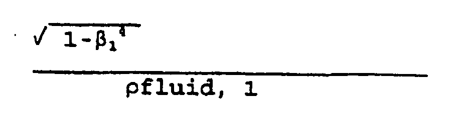
the discharge coefficient CD in multi-phase flow can be derived from the National Engineering Laboratory Report referred to above. Therefore, the volumetric flow rates for water, oil and gas are :


- Reference is now made to
Fig. 3 of the drawings which depicts a multi-flowmeter. In this example the flowmeter comprises awater fraction meter 40 upstream of afirst venturi 42. A seconddownstream venturi 44 spaced from the first venturi and between theventuris - Reference is now made to
Fig. 4 of the drawings which depicts a further alternative embodiment of the present invention. This embodiment is substantially identical to the embodiment shown inFig. 2 except that thewater fraction meter 23 is disposed downstream of theventuri 26. The same flow calculations apply but this arrangement is not preferred because gas in the multiphase fluid will have expanded because of some pressure loss in the system. - Various modifications may be made to the flowmeters hereinbefore described without departing from the scope of the invention. Although all the flowmeters are shown as a compact structure in a single conduit, it will be appreciated by persons skilled in the art that the components could be disposed between widely spaced separate conduits, for example the venturis could be disposed in different tubular elements many meters or even hundreds of meters apart.
- The present invention has the principal advantage that radio-active measurement techniques are not used and the system is flexible enough to be installed in a single conduit or as dispersed components throughout a well. A further advantage is that no moving parts are required and the system takes advantage of some of the characteristics and sensors used in two-phase in-well measurement devices and extends these through the knowledge of phase behaviour or the phases to three-phase fluid systems which has hitherto not been achieved.
Claims (11)
- A multiphase flow meter (20) for measuring the flow of a multi-phase fluid flowing through a conduit, said flow meter comprising:a first pressure measuring means (24) disposed in said conduit at a first location for measuring a first pressure differential at said first location;a second pressure measuring means (26b) disposed in said conduit at a second location spaced along said conduit downstream from said first pressure measuring means for measuring a second pressure differential at said second location;a pressure drop creation means (26a) for creating a measurable pressure drop, in use, between said first and second locations;a water fraction measuring means (23) for measuring the fraction of water in said multi-phase fluid, said water fraction meter being disposed at one of a first measurement location upstream of said first location and a second measurement location downstream of said second location; andwherein said second pressure measuring means and said pressure drop creation means comprise a double venturi (26).
- A multiphase flow meter as claimed in claim 1 wherein said multiphase flow meter utilizes a pressure, volume and temperature relationship relating to oil and gas to determine the flow rates of components of the fluid flowing in said conduit.
- A multiphase flow meter according to either of claims 1 or 2 wherein said water fraction measuring means has a capacitance sensor for calculating a water fraction of an oil-continuous fluid flowing in said conduit and a conductance sensor for calculating conductivity of a water-continuous fluid flowing in said conduit.
- A multiphase flow meter as claimed in either of claims 1 or 2 wherein said water fraction measuring means includes a microwave generator and a detector for detecting the water fraction of the fluid flowing in said conduit.
- A multiphase flow meter as claimed in either of claims 1 or 2 wherein said multiphase flow meter processes measurements from said first pressure measuring means, second pressure measuring means and water fraction measuring means to determine the flows of the components of the multiphase fluid flowing in said conduit.
- A multiphase flow meter as claimed in claim 1 wherein said multiphase flow meter utilizes a pressure, volume and temperature relationship relating to oil and gas and a volumetric shrinkage coefficient relating to oil when gas from the oil is liberated to determine the flow rates of components of the fluid flowing in said conduit.
- A multiphase flow meter as claimed in claim 1 wherein the first and second pressure measuring means, the pressure drop creation means and the water fraction measuring means are disposed in a single tubular member.
- A multiphase flow meter as claimed in claim 1 wherein the first pressure measuring means, the double venturi and the water fraction measuring means are disposed over a plurality of tubular members.
- A method of measuring the flow rate of components of a multiphase fluid flowing in a conduit, said method comprising the steps of:measuring a first pressure differential in said conduit at a first location;measuring a second pressure differential in said conduit at a second location spaced downstream from the first location and a pressure drop in said multi-phase fluid between said first and said second locations, wherein the second pressure differential and the pressure drop are created by a double venturi (26);measuring fraction of water in said multiphase fluid at one of a first measurement location upstream of said first location and a second measurement location downstream of said second location; andprocessing the first and second pressure differential measurements, pressure drop measurement and water fraction measurements to estimate the flow rates of the components of said multiphase fluid.
- A method as claimed in claim 9 wherein the method includes the step of measuring the water fraction upstream of the first location.
- A method as claimed in claim 9 or 10 further comprising using a volumetric shrinkage coefficient relating to oil when gas from the oil is liberated to determine the flow rates of components of the fluid flowing in said conduit.
Applications Claiming Priority (3)
| Application Number | Priority Date | Filing Date | Title |
|---|---|---|---|
| GBGB0029055.1A GB0029055D0 (en) | 2000-11-29 | 2000-11-29 | Apparatus for and method of measuring the flow of a multi-phase fluid |
| GB0029055 | 2000-11-29 | ||
| PCT/GB2001/005236 WO2002044664A1 (en) | 2000-11-29 | 2001-11-28 | Multiphase flow meter using multiple pressure differentials |
Publications (2)
| Publication Number | Publication Date |
|---|---|
| EP1337811A1 EP1337811A1 (en) | 2003-08-27 |
| EP1337811B1 true EP1337811B1 (en) | 2010-06-16 |
Family
ID=9904070
Family Applications (1)
| Application Number | Title | Priority Date | Filing Date |
|---|---|---|---|
| EP01998161A Expired - Lifetime EP1337811B1 (en) | 2000-11-29 | 2001-11-28 | Multiphase flow meter using multiple pressure differentials |
Country Status (10)
| Country | Link |
|---|---|
| US (1) | US6935189B2 (en) |
| EP (1) | EP1337811B1 (en) |
| AT (1) | ATE471499T1 (en) |
| AU (3) | AU2083402A (en) |
| BR (2) | BRPI0115744B1 (en) |
| CA (1) | CA2429339C (en) |
| DE (1) | DE60142403D1 (en) |
| GB (1) | GB0029055D0 (en) |
| NO (1) | NO20032312L (en) |
| WO (1) | WO2002044664A1 (en) |
Cited By (1)
| Publication number | Priority date | Publication date | Assignee | Title |
|---|---|---|---|---|
| WO2025193908A1 (en) * | 2024-03-14 | 2025-09-18 | Aramco Services Company | Compact venturi with embedded dual mutually orthogonal resonator (dmor) sensors to measure multiphase flow rates |
Families Citing this family (62)
| Publication number | Priority date | Publication date | Assignee | Title |
|---|---|---|---|---|
| US7054764B2 (en) * | 2003-09-29 | 2006-05-30 | Air Products And Chemicals, Inc. | Flow monitoring using flow control device |
| NO320172B1 (en) * | 2004-02-27 | 2005-11-07 | Roxar Flow Measurement As | Flow templates and methods for painting individual quantities of gas, hydrocarbon liquid and water in a fluid mixture |
| US20060247869A1 (en) * | 2005-04-26 | 2006-11-02 | Lucero Guillermo A | Multiphase flow meter and data system |
| US20080288181A1 (en) * | 2005-04-26 | 2008-11-20 | Guillermo Amarfil Lucero | Multiphase flow meter and data system |
| WO2007009097A1 (en) * | 2005-07-13 | 2007-01-18 | Cidra Corporation | Method and apparatus for measuring parameters of a fluid flow using an array of sensors |
| GB2430493B (en) * | 2005-09-23 | 2008-04-23 | Schlumberger Holdings | Systems and methods for measuring multiphase flow in a hydrocarbon transporting pipeline |
| ITVE20060066A1 (en) * | 2006-10-20 | 2008-04-21 | Pietro Fiorentini Spa | MEASUREMENT METHOD OF THE FLOWS OF THE DIFFERENT PHASES OF A MULTIFASE FLOW AND DEVICE FOR IMPLEMENTING THE METHOD. |
| US7866201B1 (en) * | 2007-04-09 | 2011-01-11 | The United States Of America As Represented By The United States Department Of Energy | On-line fast response device and method for measuring dissolved gas in a fluid |
| CN101363745B (en) * | 2007-08-07 | 2011-09-21 | 上海麦登电子设备有限公司 | Multiphase flow quantitative method and multiphase flow mass flowmeter |
| US7607361B2 (en) * | 2008-02-22 | 2009-10-27 | Weatherford/Lamb, Inc. | Sonar circumferential flow conditioner |
| US7707897B2 (en) * | 2008-05-27 | 2010-05-04 | Baker Hughes Incorporated | Method of measuring multiphase flow using a multi-stage flow meter |
| EP2192391A1 (en) * | 2008-12-01 | 2010-06-02 | Services Pétroliers Schlumberger | Apparatus and a method of measuring the flow of a fluid |
| NO330911B1 (en) | 2008-12-12 | 2011-08-15 | Multi Phase Meters As | Method and apparatus for measuring composition and flow rates for a wet gas |
| NO334550B1 (en) | 2008-12-12 | 2014-04-07 | Multi Phase Meters As | Method and apparatus for flow measurements for a wet gas and gas value measurements |
| US8342238B2 (en) * | 2009-10-13 | 2013-01-01 | Baker Hughes Incorporated | Coaxial electric submersible pump flow meter |
| US8061219B2 (en) * | 2010-03-02 | 2011-11-22 | Schlumberger Technology Corporation | Flow restriction insert for differential pressure measurement |
| US8429985B2 (en) * | 2010-08-24 | 2013-04-30 | General Electric Company | Apparatus for use in determining a plurality of characteristics of a multiphase flow within a pipe |
| US9581475B2 (en) | 2011-07-01 | 2017-02-28 | Schlumberger Technology Corporation | Multiphase flowmeter |
| GB2497321B (en) | 2011-12-06 | 2014-06-18 | Senico Ltd | Multi-phase metering of fluid flows |
| KR101178038B1 (en) * | 2012-05-31 | 2012-08-29 | 주식회사 태산에너지기술 | Differential pressure-type mass flow meter with double nozzles |
| US8973433B2 (en) * | 2012-06-04 | 2015-03-10 | Baker Hughes Incorporated | Dual differential pressure multiphase flow meter |
| BR112015001918B1 (en) * | 2012-08-01 | 2020-11-03 | Micro Motion, Inc. | method and fluid measurement system |
| US8801656B2 (en) * | 2012-10-29 | 2014-08-12 | Hospira, Inc. | Fluid flow passage to improve air-in-line detection |
| NO344669B1 (en) | 2012-11-21 | 2020-03-02 | Fmc Kongsberg Subsea As | A method and device for multiphase measurement in the vicinity of deposits on the pipe wall |
| US20150133861A1 (en) | 2013-11-11 | 2015-05-14 | Kevin P. McLennan | Thermal management system and method for medical devices |
| US9574438B2 (en) * | 2014-04-15 | 2017-02-21 | Baker Hughes Incorporated | Fluid velocity flow meter for a wellbore |
| US9982519B2 (en) | 2014-07-14 | 2018-05-29 | Saudi Arabian Oil Company | Flow meter well tool |
| US10143795B2 (en) | 2014-08-18 | 2018-12-04 | Icu Medical, Inc. | Intravenous pole integrated power, control, and communication system and method for an infusion pump |
| US9713286B2 (en) * | 2015-03-03 | 2017-07-18 | International Business Machines Corporation | Active control for two-phase cooling |
| DE102015105427A1 (en) * | 2015-04-09 | 2016-10-13 | Fev Gmbh | Method for the continuous measurement of the gas content in a flowing liquid and gas content measuring device for carrying out the method |
| US20160341585A1 (en) * | 2015-05-19 | 2016-11-24 | Medeng Research Institute Ltd. | Multiphase Flow Meter |
| AU2016267763B2 (en) | 2015-05-26 | 2021-07-08 | Icu Medical, Inc. | Disposable infusion fluid delivery device for programmable large volume drug delivery |
| GB2546785A (en) * | 2016-01-29 | 2017-08-02 | Yta B V | Downhole tool |
| US10712183B2 (en) | 2016-03-09 | 2020-07-14 | Onesubsea Ip Uk Limited | Determining flow rates of multiphase fluids |
| WO2018063149A1 (en) * | 2016-09-27 | 2018-04-05 | Halliburton Energy Services, Inc. | Using fluidic devices to estimate water cut in production fluids |
| US10704938B2 (en) | 2018-01-31 | 2020-07-07 | Hydroacoustics, Inc. | Pumpjack production well including fluid sensor having 2-dimensional venturi and capacitive flow sensor |
| US11906336B2 (en) | 2018-01-31 | 2024-02-20 | Hydroacoustics Inc. | Pumpjack production well including venturi fluid sensor and capacitive flow sensor |
| US11821293B2 (en) | 2018-02-07 | 2023-11-21 | Hydroacoustics. Inc. | Oil recovery tool and system |
| EP3749831B1 (en) | 2018-02-07 | 2023-12-27 | Hydroacoustics Inc. | Oil recovery tool and system |
| US12173587B2 (en) | 2018-02-07 | 2024-12-24 | Hydroacoustics Inc. | Oil recovery tool and system |
| US10648841B1 (en) | 2019-03-08 | 2020-05-12 | Saudi Arabian Oil Company | Multiphase flow meter combining extended throat venturi with microwave resonators |
| SI25849A (en) | 2019-05-23 | 2020-11-30 | Numip d.o.o. | Improved venturi element and the production method thereof |
| USD939079S1 (en) | 2019-08-22 | 2021-12-21 | Icu Medical, Inc. | Infusion pump |
| US20210063294A1 (en) * | 2019-09-03 | 2021-03-04 | Halliburton Energy Services, Inc. | In-line conical viscometer using shear stress sensors |
| US10983513B1 (en) * | 2020-05-18 | 2021-04-20 | Saudi Arabian Oil Company | Automated algorithm and real-time system to detect MPFM preventive maintenance activities |
| US11371326B2 (en) | 2020-06-01 | 2022-06-28 | Saudi Arabian Oil Company | Downhole pump with switched reluctance motor |
| US11448059B2 (en) * | 2020-08-06 | 2022-09-20 | Saudi Arabian Oil Company | Production logging tool |
| US11499563B2 (en) | 2020-08-24 | 2022-11-15 | Saudi Arabian Oil Company | Self-balancing thrust disk |
| US11920469B2 (en) | 2020-09-08 | 2024-03-05 | Saudi Arabian Oil Company | Determining fluid parameters |
| US20220090947A1 (en) * | 2020-09-23 | 2022-03-24 | Saudi Arabian Oil Company | Wide range multi-phase flow meter |
| US11644351B2 (en) | 2021-03-19 | 2023-05-09 | Saudi Arabian Oil Company | Multiphase flow and salinity meter with dual opposite handed helical resonators |
| US11591899B2 (en) | 2021-04-05 | 2023-02-28 | Saudi Arabian Oil Company | Wellbore density meter using a rotor and diffuser |
| US11913464B2 (en) | 2021-04-15 | 2024-02-27 | Saudi Arabian Oil Company | Lubricating an electric submersible pump |
| CN113738521B (en) * | 2021-08-30 | 2022-11-15 | 一汽解放汽车有限公司 | EGR flow metering system and method for natural gas engine |
| USD1052728S1 (en) | 2021-11-12 | 2024-11-26 | Icu Medical, Inc. | Medical fluid infusion pump |
| US11994016B2 (en) | 2021-12-09 | 2024-05-28 | Saudi Arabian Oil Company | Downhole phase separation in deviated wells |
| US12085687B2 (en) | 2022-01-10 | 2024-09-10 | Saudi Arabian Oil Company | Model-constrained multi-phase virtual flow metering and forecasting with machine learning |
| EP4216187B1 (en) | 2022-01-24 | 2025-01-01 | Carrier Corporation | Monitoring of the integrity of an aspirating detection system |
| US12202720B2 (en) * | 2022-03-29 | 2025-01-21 | William F. Nathan | Mechanism for dispensing fluids with compressed air |
| WO2023229914A1 (en) * | 2022-05-22 | 2023-11-30 | Chevron U.S.A. Inc. | Downhole pressure and flow rate estimation |
| US20250085144A1 (en) * | 2023-09-12 | 2025-03-13 | Saudi Arabian Oil Company | Determining hydrocarbon reservoir production with a miniature multi-phase flowmeter |
| GB2639029A (en) * | 2024-03-07 | 2025-09-10 | Taylor Hobson Ltd | Differential pressure flow meter |
Family Cites Families (14)
| Publication number | Priority date | Publication date | Assignee | Title |
|---|---|---|---|---|
| US4576043A (en) * | 1984-05-17 | 1986-03-18 | Chevron Research Company | Methods for metering two-phase flow |
| GB8719972D0 (en) * | 1987-08-24 | 1987-09-30 | Secretary Trade Ind Brit | Multi-phase flowmeter |
| US5099697A (en) * | 1990-04-02 | 1992-03-31 | Agar Corporation Ltd. | Two and three-phase flow measurement |
| GB9109957D0 (en) * | 1991-05-08 | 1991-07-03 | Schlumberger Ltd | Capacitance flow meter |
| GB2263172B (en) | 1992-01-08 | 1995-05-17 | Peco Machine Shop And Inspecti | Flow rate monitoring |
| GB9203760D0 (en) * | 1992-02-21 | 1992-04-08 | Schlumberger Ltd | Flow measurement system |
| US5461930A (en) * | 1992-03-17 | 1995-10-31 | Agar Corporation Inc. | Apparatus and method for measuring two-or three-phase fluid flow utilizing one or more momentum flow meters and a volumetric flow meter |
| GB9313818D0 (en) | 1993-07-03 | 1993-08-18 | Expro International Group The | Apparatus and a method for measuring flow rate |
| FR2720498B1 (en) * | 1994-05-27 | 1996-08-09 | Schlumberger Services Petrol | Multiphase flowmeter. |
| US5597961A (en) * | 1994-06-27 | 1997-01-28 | Texaco, Inc. | Two and three phase flow metering with a water cut monitor and an orifice plate |
| JPH08179470A (en) * | 1994-12-27 | 1996-07-12 | Fuji Photo Film Co Ltd | Photographic film cartridge |
| FR2735571B1 (en) * | 1995-06-15 | 1997-08-29 | Schlumberger Services Petrol | FLOW METER IN VENTURI FOR MEASUREMENT IN A FLUID FLOW VEIN |
| AU9509098A (en) * | 1997-09-24 | 1999-04-12 | Lockheed Martin Idaho Technologies Company | Special configuration differential pressure flow meter |
| US6345536B1 (en) | 1998-09-10 | 2002-02-12 | The Texas A&M University System | Multiple-phase flow meter |
-
2000
- 2000-11-29 GB GBGB0029055.1A patent/GB0029055D0/en not_active Ceased
-
2001
- 2001-11-28 AU AU2083402A patent/AU2083402A/en active Pending
- 2001-11-28 CA CA2429339A patent/CA2429339C/en not_active Expired - Lifetime
- 2001-11-28 US US10/433,111 patent/US6935189B2/en not_active Expired - Lifetime
- 2001-11-28 DE DE60142403T patent/DE60142403D1/en not_active Expired - Lifetime
- 2001-11-28 BR BRPI0115744-2A patent/BRPI0115744B1/en unknown
- 2001-11-28 AT AT01998161T patent/ATE471499T1/en not_active IP Right Cessation
- 2001-11-28 EP EP01998161A patent/EP1337811B1/en not_active Expired - Lifetime
- 2001-11-28 AU AU2002220834A patent/AU2002220834B2/en not_active Expired
- 2001-11-28 WO PCT/GB2001/005236 patent/WO2002044664A1/en not_active Ceased
- 2001-11-28 BR BR0115744-2A patent/BR0115744A/en active IP Right Grant
-
2003
- 2003-05-22 NO NO20032312A patent/NO20032312L/en not_active Application Discontinuation
-
2007
- 2007-04-04 AU AU2007201486A patent/AU2007201486B2/en not_active Expired
Cited By (1)
| Publication number | Priority date | Publication date | Assignee | Title |
|---|---|---|---|---|
| WO2025193908A1 (en) * | 2024-03-14 | 2025-09-18 | Aramco Services Company | Compact venturi with embedded dual mutually orthogonal resonator (dmor) sensors to measure multiphase flow rates |
Also Published As
| Publication number | Publication date |
|---|---|
| AU2007201486B2 (en) | 2009-06-25 |
| CA2429339C (en) | 2010-10-19 |
| CA2429339A1 (en) | 2002-06-06 |
| NO20032312L (en) | 2003-07-21 |
| AU2002220834B2 (en) | 2007-01-04 |
| BRPI0115744B1 (en) | 2018-04-03 |
| DE60142403D1 (en) | 2010-07-29 |
| BR0115744A (en) | 2004-01-13 |
| EP1337811A1 (en) | 2003-08-27 |
| US6935189B2 (en) | 2005-08-30 |
| AU2007201486A1 (en) | 2007-04-26 |
| WO2002044664A1 (en) | 2002-06-06 |
| ATE471499T1 (en) | 2010-07-15 |
| GB0029055D0 (en) | 2001-01-10 |
| NO20032312D0 (en) | 2003-05-22 |
| AU2083402A (en) | 2002-06-11 |
| US20040182172A1 (en) | 2004-09-23 |
Similar Documents
| Publication | Publication Date | Title |
|---|---|---|
| US6935189B2 (en) | Multiphase flow meter using multiple pressure differentials | |
| AU2002220834A1 (en) | Multiphase flow meter using multiple pressure differentials | |
| RU2243510C2 (en) | Multiphase flow measurements in pipeline | |
| US7707897B2 (en) | Method of measuring multiphase flow using a multi-stage flow meter | |
| US4776210A (en) | Multiphase fluid flow measurement systems and methods | |
| EP2423647B1 (en) | Apparatus for use in determining a plurality of characteristics of a multiphase flow within a pipe | |
| US6467358B1 (en) | Method of measuring flow rates of respective fluids constituting multiphase fluid and flow meter for multiphase flow utilizing same | |
| EP0372598B1 (en) | Impedance cross correlation logging tool | |
| US8973433B2 (en) | Dual differential pressure multiphase flow meter | |
| US7293471B2 (en) | Flow meter for measuring fluid mixtures | |
| US20090308601A1 (en) | Evaluating multiphase fluid flow in a wellbore using temperature and pressure measurements | |
| US8065923B2 (en) | Method and apparatus for measuring the flow rates of the individual phases of a multiphase fluid mixture | |
| WO1995033980A1 (en) | Multiphase fluid flow rate and density measurement | |
| Lucas et al. | Measurement of the homogeneous velocity of inclined oil-in-water flows using a resistance cross correlation flow meter | |
| Rajan et al. | Multiphase flow measurement techniques—a review | |
| Lucas et al. | Flow rate measurement by kinematic wave detection in vertically upward, bubbly two-phase flows | |
| WO2019152353A1 (en) | Measuring fluid density in a fluid flow | |
| WO1993022628A1 (en) | Flowrate monitoring apparatus for multiphase fluids | |
| AU7078194A (en) | Apparatus and a method for measuring flow rate | |
| Lucas et al. | Investigation of a drift velocity model for predicting superficial velocities of oil and water in inclined oil-in-water pipe flows with a centre body | |
| Tonkonog et al. | Experience of Application of Different Multiphase Metering Technologies for Cold Production and High Viscosity Oil Systems |
Legal Events
| Date | Code | Title | Description |
|---|---|---|---|
| PUAI | Public reference made under article 153(3) epc to a published international application that has entered the european phase |
Free format text: ORIGINAL CODE: 0009012 |
|
| 17P | Request for examination filed |
Effective date: 20030520 |
|
| AK | Designated contracting states |
Designated state(s): AT BE CH CY DE DK ES FI FR GB GR IE IT LI LU MC NL PT SE TR |
|
| AX | Request for extension of the european patent |
Extension state: AL LT LV MK RO SI |
|
| RIN1 | Information on inventor provided before grant (corrected) |
Inventor name: RICHARDS, ANDREW |
|
| 17Q | First examination report despatched |
Effective date: 20060919 |
|
| GRAP | Despatch of communication of intention to grant a patent |
Free format text: ORIGINAL CODE: EPIDOSNIGR1 |
|
| GRAS | Grant fee paid |
Free format text: ORIGINAL CODE: EPIDOSNIGR3 |
|
| GRAA | (expected) grant |
Free format text: ORIGINAL CODE: 0009210 |
|
| AK | Designated contracting states |
Kind code of ref document: B1 Designated state(s): AT BE CH CY DE DK ES FI FR GB GR IE IT LI LU MC NL PT SE TR |
|
| REG | Reference to a national code |
Ref country code: CH Ref legal event code: EP |
|
| REG | Reference to a national code |
Ref country code: IE Ref legal event code: FG4D |
|
| REF | Corresponds to: |
Ref document number: 60142403 Country of ref document: DE Date of ref document: 20100729 Kind code of ref document: P |
|
| REG | Reference to a national code |
Ref country code: NL Ref legal event code: VDEP Effective date: 20100616 |
|
| PG25 | Lapsed in a contracting state [announced via postgrant information from national office to epo] |
Ref country code: SE Free format text: LAPSE BECAUSE OF FAILURE TO SUBMIT A TRANSLATION OF THE DESCRIPTION OR TO PAY THE FEE WITHIN THE PRESCRIBED TIME-LIMIT Effective date: 20100616 |
|
| PG25 | Lapsed in a contracting state [announced via postgrant information from national office to epo] |
Ref country code: AT Free format text: LAPSE BECAUSE OF FAILURE TO SUBMIT A TRANSLATION OF THE DESCRIPTION OR TO PAY THE FEE WITHIN THE PRESCRIBED TIME-LIMIT Effective date: 20100616 Ref country code: FI Free format text: LAPSE BECAUSE OF FAILURE TO SUBMIT A TRANSLATION OF THE DESCRIPTION OR TO PAY THE FEE WITHIN THE PRESCRIBED TIME-LIMIT Effective date: 20100616 |
|
| PG25 | Lapsed in a contracting state [announced via postgrant information from national office to epo] |
Ref country code: GR Free format text: LAPSE BECAUSE OF FAILURE TO SUBMIT A TRANSLATION OF THE DESCRIPTION OR TO PAY THE FEE WITHIN THE PRESCRIBED TIME-LIMIT Effective date: 20100917 Ref country code: CY Free format text: LAPSE BECAUSE OF FAILURE TO SUBMIT A TRANSLATION OF THE DESCRIPTION OR TO PAY THE FEE WITHIN THE PRESCRIBED TIME-LIMIT Effective date: 20100616 |
|
| PG25 | Lapsed in a contracting state [announced via postgrant information from national office to epo] |
Ref country code: NL Free format text: LAPSE BECAUSE OF FAILURE TO SUBMIT A TRANSLATION OF THE DESCRIPTION OR TO PAY THE FEE WITHIN THE PRESCRIBED TIME-LIMIT Effective date: 20100616 |
|
| PG25 | Lapsed in a contracting state [announced via postgrant information from national office to epo] |
Ref country code: BE Free format text: LAPSE BECAUSE OF FAILURE TO SUBMIT A TRANSLATION OF THE DESCRIPTION OR TO PAY THE FEE WITHIN THE PRESCRIBED TIME-LIMIT Effective date: 20100616 Ref country code: PT Free format text: LAPSE BECAUSE OF FAILURE TO SUBMIT A TRANSLATION OF THE DESCRIPTION OR TO PAY THE FEE WITHIN THE PRESCRIBED TIME-LIMIT Effective date: 20101018 |
|
| PG25 | Lapsed in a contracting state [announced via postgrant information from national office to epo] |
Ref country code: IT Free format text: LAPSE BECAUSE OF FAILURE TO SUBMIT A TRANSLATION OF THE DESCRIPTION OR TO PAY THE FEE WITHIN THE PRESCRIBED TIME-LIMIT Effective date: 20100616 |
|
| PLBE | No opposition filed within time limit |
Free format text: ORIGINAL CODE: 0009261 |
|
| STAA | Information on the status of an ep patent application or granted ep patent |
Free format text: STATUS: NO OPPOSITION FILED WITHIN TIME LIMIT |
|
| PG25 | Lapsed in a contracting state [announced via postgrant information from national office to epo] |
Ref country code: DK Free format text: LAPSE BECAUSE OF FAILURE TO SUBMIT A TRANSLATION OF THE DESCRIPTION OR TO PAY THE FEE WITHIN THE PRESCRIBED TIME-LIMIT Effective date: 20100616 |
|
| 26N | No opposition filed |
Effective date: 20110317 |
|
| PG25 | Lapsed in a contracting state [announced via postgrant information from national office to epo] |
Ref country code: MC Free format text: LAPSE BECAUSE OF NON-PAYMENT OF DUE FEES Effective date: 20101130 |
|
| REG | Reference to a national code |
Ref country code: CH Ref legal event code: PL |
|
| REG | Reference to a national code |
Ref country code: DE Ref legal event code: R097 Ref document number: 60142403 Country of ref document: DE Effective date: 20110316 Ref country code: DE Ref legal event code: R097 Ref document number: 60142403 Country of ref document: DE Effective date: 20110317 |
|
| GBPC | Gb: european patent ceased through non-payment of renewal fee |
Effective date: 20101128 |
|
| PG25 | Lapsed in a contracting state [announced via postgrant information from national office to epo] |
Ref country code: CH Free format text: LAPSE BECAUSE OF NON-PAYMENT OF DUE FEES Effective date: 20101130 Ref country code: LI Free format text: LAPSE BECAUSE OF NON-PAYMENT OF DUE FEES Effective date: 20101130 |
|
| REG | Reference to a national code |
Ref country code: FR Ref legal event code: ST Effective date: 20110801 |
|
| REG | Reference to a national code |
Ref country code: DE Ref legal event code: R119 Ref document number: 60142403 Country of ref document: DE Effective date: 20110601 Ref country code: DE Ref legal event code: R119 Ref document number: 60142403 Country of ref document: DE Effective date: 20110531 |
|
| PG25 | Lapsed in a contracting state [announced via postgrant information from national office to epo] |
Ref country code: FR Free format text: LAPSE BECAUSE OF NON-PAYMENT OF DUE FEES Effective date: 20101130 Ref country code: IE Free format text: LAPSE BECAUSE OF NON-PAYMENT OF DUE FEES Effective date: 20101128 |
|
| PG25 | Lapsed in a contracting state [announced via postgrant information from national office to epo] |
Ref country code: GB Free format text: LAPSE BECAUSE OF NON-PAYMENT OF DUE FEES Effective date: 20101128 |
|
| PG25 | Lapsed in a contracting state [announced via postgrant information from national office to epo] |
Ref country code: LU Free format text: LAPSE BECAUSE OF NON-PAYMENT OF DUE FEES Effective date: 20101128 |
|
| PG25 | Lapsed in a contracting state [announced via postgrant information from national office to epo] |
Ref country code: TR Free format text: LAPSE BECAUSE OF FAILURE TO SUBMIT A TRANSLATION OF THE DESCRIPTION OR TO PAY THE FEE WITHIN THE PRESCRIBED TIME-LIMIT Effective date: 20100616 |
|
| PG25 | Lapsed in a contracting state [announced via postgrant information from national office to epo] |
Ref country code: DE Free format text: LAPSE BECAUSE OF NON-PAYMENT OF DUE FEES Effective date: 20110531 |
|
| PG25 | Lapsed in a contracting state [announced via postgrant information from national office to epo] |
Ref country code: ES Free format text: LAPSE BECAUSE OF FAILURE TO SUBMIT A TRANSLATION OF THE DESCRIPTION OR TO PAY THE FEE WITHIN THE PRESCRIBED TIME-LIMIT Effective date: 20100927 |