EP1337355B1 - Can lid closure and method of joining a can lid closure to a can body - Google Patents
Can lid closure and method of joining a can lid closure to a can body Download PDFInfo
- Publication number
- EP1337355B1 EP1337355B1 EP01991513A EP01991513A EP1337355B1 EP 1337355 B1 EP1337355 B1 EP 1337355B1 EP 01991513 A EP01991513 A EP 01991513A EP 01991513 A EP01991513 A EP 01991513A EP 1337355 B1 EP1337355 B1 EP 1337355B1
- Authority
- EP
- European Patent Office
- Prior art keywords
- lid
- inches
- chuck
- radially outward
- angle
- Prior art date
- Legal status (The legal status is an assumption and is not a legal conclusion. Google has not performed a legal analysis and makes no representation as to the accuracy of the status listed.)
- Expired - Lifetime
Links
Images

Classifications
-
- B—PERFORMING OPERATIONS; TRANSPORTING
- B21—MECHANICAL METAL-WORKING WITHOUT ESSENTIALLY REMOVING MATERIAL; PUNCHING METAL
- B21D—WORKING OR PROCESSING OF SHEET METAL OR METAL TUBES, RODS OR PROFILES WITHOUT ESSENTIALLY REMOVING MATERIAL; PUNCHING METAL
- B21D51/00—Making hollow objects
- B21D51/16—Making hollow objects characterised by the use of the objects
- B21D51/38—Making inlet or outlet arrangements of cans, tins, baths, bottles, or other vessels; Making can ends; Making closures
-
- B—PERFORMING OPERATIONS; TRANSPORTING
- B21—MECHANICAL METAL-WORKING WITHOUT ESSENTIALLY REMOVING MATERIAL; PUNCHING METAL
- B21D—WORKING OR PROCESSING OF SHEET METAL OR METAL TUBES, RODS OR PROFILES WITHOUT ESSENTIALLY REMOVING MATERIAL; PUNCHING METAL
- B21D51/00—Making hollow objects
- B21D51/16—Making hollow objects characterised by the use of the objects
- B21D51/26—Making hollow objects characterised by the use of the objects cans or tins; Closing same in a permanent manner
- B21D51/30—Folding the circumferential seam
- B21D51/32—Folding the circumferential seam by rolling
-
- B—PERFORMING OPERATIONS; TRANSPORTING
- B21—MECHANICAL METAL-WORKING WITHOUT ESSENTIALLY REMOVING MATERIAL; PUNCHING METAL
- B21D—WORKING OR PROCESSING OF SHEET METAL OR METAL TUBES, RODS OR PROFILES WITHOUT ESSENTIALLY REMOVING MATERIAL; PUNCHING METAL
- B21D51/00—Making hollow objects
- B21D51/16—Making hollow objects characterised by the use of the objects
- B21D51/38—Making inlet or outlet arrangements of cans, tins, baths, bottles, or other vessels; Making can ends; Making closures
- B21D51/44—Making closures, e.g. caps
-
- B—PERFORMING OPERATIONS; TRANSPORTING
- B65—CONVEYING; PACKING; STORING; HANDLING THIN OR FILAMENTARY MATERIAL
- B65D—CONTAINERS FOR STORAGE OR TRANSPORT OF ARTICLES OR MATERIALS, e.g. BAGS, BARRELS, BOTTLES, BOXES, CANS, CARTONS, CRATES, DRUMS, JARS, TANKS, HOPPERS, FORWARDING CONTAINERS; ACCESSORIES, CLOSURES, OR FITTINGS THEREFOR; PACKAGING ELEMENTS; PACKAGES
- B65D7/00—Containers having bodies formed by interconnecting or uniting two or more rigid, or substantially rigid, components made wholly or mainly of metal
- B65D7/12—Containers having bodies formed by interconnecting or uniting two or more rigid, or substantially rigid, components made wholly or mainly of metal characterised by wall construction or by connections between walls
- B65D7/34—Containers having bodies formed by interconnecting or uniting two or more rigid, or substantially rigid, components made wholly or mainly of metal characterised by wall construction or by connections between walls with permanent connections between walls
- B65D7/36—Containers having bodies formed by interconnecting or uniting two or more rigid, or substantially rigid, components made wholly or mainly of metal characterised by wall construction or by connections between walls with permanent connections between walls formed by rolling, or by rolling and pressing
-
- B—PERFORMING OPERATIONS; TRANSPORTING
- B65—CONVEYING; PACKING; STORING; HANDLING THIN OR FILAMENTARY MATERIAL
- B65D—CONTAINERS FOR STORAGE OR TRANSPORT OF ARTICLES OR MATERIALS, e.g. BAGS, BARRELS, BOTTLES, BOXES, CANS, CARTONS, CRATES, DRUMS, JARS, TANKS, HOPPERS, FORWARDING CONTAINERS; ACCESSORIES, CLOSURES, OR FITTINGS THEREFOR; PACKAGING ELEMENTS; PACKAGES
- B65D2517/00—Containers specially constructed to be opened by cutting, piercing or tearing of wall portions, e.g. preserving cans or tins
- B65D2517/0001—Details
- B65D2517/0058—Other details of container end panel
- B65D2517/0059—General cross-sectional shape of container end panel
- B65D2517/0061—U-shaped
- B65D2517/0062—U-shaped and provided with an additional U-shaped peripheral channel
Definitions
- the present invention relates generally to metal containers, and more particularly to metal cans.
- Aluminum cans are used primarily as containers for retail sale of beverages in individual portions. Annual sales of such cans are in the billions and consequently, over the years, their design has been refined to reduce cost and improve performance. Other refinements have been made for ecological purposes, to improve reclamation and promote recycling.
- Performance improvements may be functional in nature, such as better sealing and higher ultimate pressure capacity. Such improvements can allow the use of thinner sheet metal, which leads directly to material cost reductions. Performance improvements may also be ergonomic in nature, such as a can end configured to allow for easier pull tab access or better lip contact.
- Aluminum cans are usually formed from a precoated aluminum alloy, such as the aluminum alloy 5182.
- the cans which are typically made from relatively thin sheet metal, must be capable of withstanding pressures approaching 6,8948 bar (100 psi), with 6,2053 bar (90 psi) being an industry recognized requirement.
- the cans are usually formed from a can body to which is joined a can lid or closure.
- Each of these components has certain specifications and requirements. For instance, the upper surface of the can lids must be configured to nest with the lower surface of the can bottoms so that the cans can be easily stacked one on top of the other. It is also desirable to have the can lids themselves nest with each other in a stacked arrangement for handling and shipping purposes prior to attaching the can lid to the can body. The ability to satisfy these functional requirements with the use of ever less material continues to develop.
- Patent Cooperation Treaty International Publication Number WO 96/37414 describes a can lid design for reduced metal usage.
- This can lid comprises a peripheral portion or "curl,” a frustoconical chuckwall depending from the interior of the peripheral curl, an outwardly concave annular reinforcing bead or “countersink” extending radially inwards from the chuckwall, and a center panel supported by the inner portion of the countersink.
- the frustoconical chuckwall is inclined at an angle of between 20° and 60° with respect to an axis perpendicular to the center panel.
- the chuckwall connects the countersink and peripheral curl and is the portion of the lid the seaming chuck contacts during the seaming process.
- a double seam is formed between the can end and a can body by a process wherein the peripheral curl is centered on the can body flange by a chuck that is partially frustoconical and partially cylindrical.
- the frustoconical portion of the chuck is designed to contact the frustoconical chuckwall of the can lid.
- the overlap of the peripheral curl on the lid with the can body flange is described to be by a conventional amount.
- Rotation of the can lid/can body, first against a seaming roll and then a flattening roll completes a double seam between the two parts. During the flattening portion of the operation, the portion of the chuckwall adjacent to the peripheral curl is bent and flattened against the cylindrical surface of the chuck.
- the lid of International Publication Number WO 96/37414 incorporates known dimensions for the peripheral curl portion which is seamed to the can.
- the can lid of International Publication Number WO 96/37414 is also susceptible to increased metal deformation during seaming and failure at lower pressures.
- U.S. Patent No. 6,065,634 (Brifcani), describes the same can lid design as described in International Publication Number WO 96/37414.
- a can lid design which is a modification of the WO 96/37414 can lid wherein the chuckwall is in two parts.
- This can lid comprises a peripheral portion or "curl,” a two-part chuckwall depending from the interior of the peripheral curl, an outwardly concave annular reinforcing bead or "countersink” extending radially inwards from the chuckwall, and a center panel supported by the inner portion of the countersink.
- the first part of the chuckwall is frustoconical and adjacent to the curl, and is inclined to an axis perpendicular to the central panel at an angle between 1 and 39 degrees, typically between 7 and 14 degrees.
- the second part of the chuckwall is frustoconical and adjacent to the reinforcing bead, and is inclined to an axis perpendicular to the central panel at an angle between 30 and 60 degrees, preferably between 40 and 45 degrees.
- a double seam is formed between the can end and a can body by a process wherein the peripheral curl is centered on the can body flange by a two-part chuck having frustoconical and cylindrical portions as in WO 96/37414.
- Rotation of the can lid/can body, first against a seaming tool and then a flattening roll completes a double seam between the two parts.
- the first portion of the chuckwall, adjacent to the peripheral curl is deformed to contact the cylindrical surface of the chuck.
- the present invention contemplates improved aluminum can lids with reduced aluminum usage, reduced reforming of the lid during seaming operations and an improved seam between the lid and the can body.
- a preferred embodiment of the disclosed can lid has a center panel having a central axis that is perpendicular to a diameter of the outer rim of the can lid, an annular countersink extending radially outward from the center panel, an arcuate portion extending radially outward and upward from the annular countersink, a step portion extending radially outward and upward from the arcuate portion, a first transitional portion extending radially outward and upward from the step portion, a second transitional portion extending radially outward from the first transitional portion, and a peripheral curl extending radially outward from the second transitional portion.
- the preferred embodiment is adapted for use with a seaming chuck having an upper frustoconical drive portion, a recessed portion, and a lower drive portion.
- the chuck 44 was designed to have a driving surface 46 configured to contact and engage with arcuate chuckwall 132 during the seaming process, hence the use of the term "chuckwall" in describing the portion designated as 132.
- the PCT/US00/42561 application disclosed a step portion 34 that extends radially outward from the arcuate chuckwall, a transitional portion 36 that extends radially outward from the step portion, and a peripheral curl portion 38 that extends radially outward from the transitional portion.
- the lid of the current invention has been further developed and modified, primarily with respect to the portion previously referred to as the "chuckwall,” and its surrounding portions, and the points of contact for the chuck during seaming.
- the portion of the lid referred to as the chuckwall 132 in the PCT/US00/42561 application generally corresponds to the portion referred to as arcuate portion 132 in the current invention, although the range of the radius of curvature of these two arcuate portions are not the same.
- the designation as "chuckwall” has been removed because the chuck 144 of the present invention does not contact or engage with arcuate portion 132 as the chuck 44 contacted the chuckwall 132 in the previous application.
- the points of contact for the chuck in the current invention are apparent in the detailed description of the drawings below.
- step portion 34 in the PCT/US00/42561 application corresponds to the step portion 134 described herein, with both portions having the same range of radius of curvature.
- the transitional portion 36 in the PCT/US00/42561 application now consists of two discrete parts in the current invention, generally corresponding to the first transitional portion 136 and the second transitional portion 137. As described below, the first transitional portion 136 is angular relative to the central axis and the second transitional portion 137 has approximately the same ranges for the radius of curvature described for the transitional portion 36 in the previous application.
- the peripheral curl portion 38 in the PCT/US00/42561 application generally corresponds to the peripheral curl portion 138 in the current invention, with approximately the same ranges for the radius of curvature for these portions.
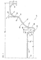
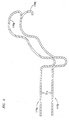
- FIGURE 1 is a cross-sectional view of a portion of a can lid 110, illustrative of the currently preferred embodiment of the present invention.
- Can lid 110 is preferably made from aluminum sheet metal.
- an aluminum alloy is used, such as aluminum alloy 5182.
- the sheet metal typically has a thickness of from about 0,198 to about 0,254 mm (0.007 to about 0.010 inches), more preferably from about 0,191 to about 0,224 mm (0.0075 to about 0.0088 inches), and still more preferably from about 0,198 to about 0,211 mm (0.0078 to about 0.0083 inches).
- the sheet metal may be coated with a coating (not shown) on at least one side. This coating is usually provided on that side of the sheet metal that will form the interior of the can.
- a coating not shown
- the can lid 110 has a center panel 112.
- the center panel 112 is generally circular in shape but may be intentionally noncircular.
- the center panel 112 may have a diameter d 1 of from about 3,56 to about 5,08 cm (1.4 to about 2.0 inches), more preferably from about 4,06 to about 4,57 cm (1.6 to about 1.8 inches), still more preferably from about 4,19 to about 4,45 cm (1.65 to about 1.75 inches), and most preferably 4,29 cm (1.69 inches).
- d 1 of from about 3,56 to about 5,08 cm (1.4 to about 2.0 inches), more preferably from about 4,06 to about 4,57 cm (1.6 to about 1.8 inches), still more preferably from about 4,19 to about 4,45 cm (1.65 to about 1.75 inches), and most preferably 4,29 cm (1.69 inches).
- the center panel 112 is shown as being flat, it may also have a peaked or domed configuration as well, and is not necessarily limited to the flat or planar configuration shown.
- the center panel 112 has a central axis 114 that is perpendicular to a diameter d 2 of the outer rim, or peripheral curl portion 138, of can lid 110.
- Diameter d 2 is from about 5,72 to about 6,35 cm (2.25 to 2.50 inches), with a target diameter of 5,94 cm (2.34 inches).
- the diameter d 1 of center panel 112 is preferably less than 80% of the diameter d 2 of the outer rim.
- annular countersink 116 Surrounding the center panel is an annular countersink 116 that is formed from an interior wall 120 and an exterior wall 128, which are spaced apart and extend radially outward from a curved bottom portion 124.
- the inner and outer walls 120, 128 are generally flat and may be parallel to one another and to the central axis 114 but either or both may diverge by an angle of about as much as 15°.
- the annular counter sink 116 extends radially downward from the center panel 112 along the upper edge of the interior wall 120.
- the curved juncture 118 extending radially inward from interior wall 120 toward the center panel 112 has a radius of curvature r 1 that is from about 0,33 to about 0,432 mm (0.013 to about 0.017 inches), more preferably from about 0,356 to about 0,406 mm (0.014 to about 0.016 inches), still more preferably from about 0,375 to about 0,387 mm (0.01475 to about 0.01525 inches), and most preferably 0,381 mm (0.15 inches).
- Bottom portion 124 preferably has a radius of curvature r 2 .
- Radius of curvature r 2 is from about 0,762 to about 1,520 mm (0.030 to about 0.060 inches), and still more preferably from about 0,889 to about 1,27 mm (0.035 to about 0.05 inches), and most preferably about 0,965 mm (0.038 inches).
- the center-point of radius of curvature r 2 is located below the profile of can lid 110.
- the annular countersink 116 has a height h 1 of from about 0,762 to about 2,92 mm (0.03 to about 0.115 inches), more preferably from about 1,27 to about 2.41 mm (0.05 to about 0.095 inches), and still more preferably from about 1,52 to about 2,16 mm (0.06 to about 0.085 inches).
- the bottom portion 124 of annular countersink 116 may also be formed with different inner and outer radii extending radially outward from a flat portion.
- the outer wall 128 contains a second chuck contacting portion 228 that is one of two points at which the chuck comes in contact with the interior of the can lid 110 during the seaming operation.
- An arcuate portion 132 extends radially outward and upward from the outer wall 128 by means of curved juncture 130 having a radius of curvature r 4 of from about 0,762 to about 1,78 mm (0.03 to about 0.07 inches), more preferably from about 0,889 to about 1,52 mm (0.035 to about 0.06 inches), still more preferably from about 0,953 to about 1,27 mm (0.0375 to about 0.05 inches), and most preferably about 1,02 mm (0.04 inches).
- the center-point of radius of curvature r 4 is located below the profile of can lid 110.
- the arcuate portion132 is shown as having a radius of curvature r 5 that is from about 2,54 to about 7,62 mm (0.100 to about 0.300 inches), more preferably from about 4,06 to about 5,59 mm (0.160 to about 0.220 inches), and still more preferably from about 4,57 to about 5,08 mm (0.180 to about 0.200 inches).
- the current design parameter for radius of curvature r 5 is 0,475 mm (0.0187 inches).
- the center-point of radius of curvature r 5 is located below the profile of can lid 110.
- the arcuate portion 132 is configured such that a line passing through the innermost end of arcuate portion 132, near the terminus of curved juncture 130, and the outermost end of the arcuate portion 132, near the beginning of step portion 134, forms an acute angle with respect to central axis 114 of the center panel 112.
- This acute angle is from about 20° to about 80°, and more preferably from about 35° to about 65°, and still more preferably from about 45° to about 55°.
- the current lid design uses an angle of about 50°.
- the step portion 134 extends radially outward from the arcuate portion 132.
- Step portion 134 is preferably curved with a radius of curvature r 6 of from about 0,508 to about 1,52 mm (0.02 to about 0.06 inches), more preferably from about 0,635 to about 1,4 mm (0.025 to about 0.055 inches), still more preferably from about 0,762 to about 1,27 mm (0.03 to about 0.05 inches), and most preferably from about 0,889 to about 1,14 mm (0.035 to about 0.045 inches).
- the current lid design parameter for radius of curvature r 6 is 1,02 mm (0.040 inches).
- the radius of curvature r 6 has a center-point located above the profile of the can lid 110.
- First transitional portion 136 extends radially upward and slightly outward from step portion 134.
- First transitional portion 136 forms an angle a 1 with respect to central axis 114 of the center panel 112. This angle is from about 4° to about 12°, more preferably from about 5° to about 7°, and most preferably about 6°.
- angle a 1 is intended to be slightly larger than angle a 2 , which is formed by driving surface 146 of chuck 144 with respect to central axis 114 of the center panel 112.
- the difference between angle a 1 and angle a 2 is no greater than about 4°, and at least about 0.5°.
- the difference between angle a 1 and angle a 2 is at least about 1°, and not more than about 3°. Most preferably, the difference between angle a 1 and angle a 2 is about 2°. Angle a 2 is preferably at least about 2° to aid in removing the can from the chuck 144 after the seaming operation and preferably not greater than about 8°. The current design parameter for angle a 2 is about 4°.
- Second transitional portion 137 extends radially outward from first transitional portion 136.
- Second transitional portion 137 has a radius of curvature r 7 of from about 1,02 to about 2,29 mm (0.04 to about 0.09 inches), more preferably from about 1,14 to about 2,03 mm (0.045 to about 0.08 inches), and still more preferably from about 1,27 to about 1,65 mm (0.05 to about 0.065 inches).
- Peripheral curl portion 138 extends radially outward from second transitional portion 137.
- Peripheral curl portion 138 has a height h 2 of from about 1,02 to about 2,29 mm (0.04 to about 0.09 inches), more preferably from about 1,21 to about 2,1 mm (0.0475 to about 0.0825 inches), still more preferably from about 1,65 to about 2,1 mm (0.065 to about 0.0825 inches), and most preferably from about 1,91 to about 2,1 mm (0.075 to about 0.0825 inches).
- the current design parameter for height h 2 is 1,98 cm (0.078 inches).
- FIGURE 2 shows the combined height h 6 of the first transitional portion 136 and second transitional portion 137 as being approximately 2.67mm (0.105 inches) for the current design parameter. This height is slightly greater than the height of the finished double seam, which is from about 2,44 to about 2,54 mm (0.096 to about 0.100 inches) on the current can design.
- a reduced seam version of the can has a finished double seam with a height of from about 1,73 to about 2,03 mm (0.068 to about 0.080 inches), with the height h 6 of first transitional portion 136 and second transitional portion 137 being approximately 2,08mm (0.082 inches).
- a micro-seam version of the can has a finished double seam with a height of from about 1,27 to about 1,4 mm (0.050 to about 0.055 inches), with the height h 6 of the first transitional portion 136 and second transitional portion 137 being approximately 1,52 mm (0.060 inches).
- the greater height h 6 provides an area to generate a finished seam pressure ridge, at the bottom of the double seam, which tightens the final seam and prevents leakage.
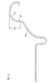
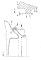
- FIGURE 3 shows can lid 110 resting on can body 140, and particularly resting on flange 142 of can body 140.
- the radius of the can flange 142 is slightly smaller than the second transitional portion radius r 7 . Because the flange radius and second transitional portion radius are very similar, the lid easily centralizes on the can for seaming.
- the can body has an inside neck diameter d 3 from about 5,21 to about 5,25 cm (2.051 to about 2.065 inches), with a target diameter of about 5,23 cm (2.058 inches).
- Can body 140 is supported by a base plate 145 (not shown) which together with chuck 144 is mounted for rotation about axis 114.
- Chuck 144 includes an upper driving surface 146 configured to match and engage with the surface of step portion 134.
- upper driving surface 146 is comprised of an upper frustoconical portion 146a characterized by angle a 2 and a lower curved portion 146b characterized by a radius selected to engage with step portion 134 having a radius r 6 .
- Chuck 144 also includes a lower driving surface 148 configured to match and engage with the second chuck contacting portion 228 of the annular countersink 116.
- Recessed portion 232 of the chuck 144 extends between the driving surfaces 146 and 148 and is configured not to contact or deform the arcuate portion 132 of lid 110.
- the size of the gap between recessed portion 232 and arcuate portion 132 as shown in Figure 3 is not considered critical and is not shown to scale.
- the approximately 6° angle a 1 which first transitional portion 136 forms with respect to central axis 114 of the center panel 112, coupled with the two chuck driving points, the step portion 134, and the second chuck contacting portion 228, further improves the alignment between the chuck 144 and the lid 110.
- a limited clamping force between chuck 144 and base plate 145 (not shown) provides adequate friction between chuck 144 and step portion 134 and second chuck contacting portion 228 for positive rotation of can lid 110 and can body 140. Because the chuck 144 drives the lid at two points, the step portion 134 and second chuck contacting portion 228, the clamping force required to prevent skidding of the lid during the seaming process is reduced to a range of about 70 to about 140 pounds.
- Driving surface 146 of chuck 144 forms an angle a 2 that is approximately 4° with respect to central axis 114 of the center panel 112. This angle provides for removing of the can from the chuck 144 after the seaming operation.
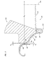
- FIGURE 4 shows the initial stage of double seam formation between can lid 110 and can body 140.
- Roller 150 bears against peripheral curl portion 138 and the centering force exerted by chuck 144.
- Chuck 144 using upper driving surface 146 and lower driving surface 148, drives can lid 110 and can body 140 to rotate, generating a rolling, swaging action that reforms second transitional portion 137, peripheral curl portion 138, and flange 142 into an intermediate peripheral seam 152.
- Step portion 134 bears against upper driving surface 146 to support second transitional portion 137, and peripheral curl portion 138 leads the rolling deformation against roller 150.
- Note that there is very little movement of first transitional portion 136 during seaming because it is at nearly the same angle as that of the upper driving surface 146 of chuck 144.
- pressure from roller 150 is applied to the peripheral curl portion 138, the second transitional portion 137 is pressed against the chuck 144, further improving the driving of the lid 110.
- positive support and guidance work together to achieve consistent and reliable results in producing
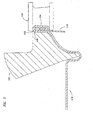
- FIGURE 5 shows the final stage of forming a double seam between can lid 110 and can body 140.
- roller 150 bears against intermediate peripheral seam 152 as it is supported by chuck 144.
- Chuck 144 drives can lid 110 and can body 140 to rotate, so that the pressure of roller 150 flattens intermediate peripheral seam 152 against upper portion 148 of chuck 144, producing double seam 154.
- Upper portion 148 of chuck 144 has a draft angle for ease of separation of can lid 110 after this operation.
- FIGURE 6 shows the manner in which a plurality of can lids 110a and 110b stack for handling, packaging, and feeding a seaming machine. Underside of peripheral curl 13 8a bears down against upper portion of peripheral curl 138b of adjacent can lid 110b. Can lid 110a is supported and separated from can lid 110b by a height h 3 sufficient to accommodate the thickness of a pull-tab (not shown). In this manner, can lids 110 are compactly and efficiently handled and are more readily positioned for magazine feeding of a mechanized seaming operation.
- FIGURE 7 shows the manner of stacking filled can 164a, closed and sealed according to the present invention on a like filled can 164b. Stand bead 166a rests upon double seam 154b.
- FIGURE 8 shows those portions of the chuck 144 shown in FIGURE 3, and described above, and also provides a more detailed view of the upper frustoconical portion 146a and lower curved portion 146b of the upper driving surface 146.
Landscapes
- Engineering & Computer Science (AREA)
- Mechanical Engineering (AREA)
- Rigid Containers With Two Or More Constituent Elements (AREA)
- Containers Opened By Tearing Frangible Portions (AREA)
- Closures For Containers (AREA)
- Electroplating And Plating Baths Therefor (AREA)
- Electroplating Methods And Accessories (AREA)
- Seal Device For Vehicle (AREA)
Abstract
Description
Claims (16)
- A lid (110) for a can body (140) comprising:characterized bya center panel (112) having a central axis (114) that is perpendicular to a diameter of an outer rim of said lid; andan annular countersink portion (116) extending radially outward from said center panel (112);
an arcuate portion (132) extending radially outward from said annular countersink (116), and having a radius of not greater than 1,27 cm (0,5 inches) with a center point below the surface of the lid (110), wherein a line passing through the ends of said arcuate portion (132) is at an angle with respect to said central axis (114) of the center panel (112) of from about 20° to about 80°;
a step portion (134) extending radially outward from said arcuate portion (132) and having a radius of at least 0,0254 cm (0,010 inches), with a center point above the surface of the lid (110);
a first transitional portion (136) extending radially outward from said step portion (134) and being generally frustoconical and inclined at an angle with respect to said central axis (114) of at least about 4° and not more than about 12°;
a second transitional portion (137) extending radially outward from said first transitional portion (136) and having by a radius of at least 0,0508 cm (0,020 inches) with a center point below the surface of the lid (110); and
a peripheral curl portion (138) extending radially outward from the second transitional portion (137). - The can lid (110) according to claim 1 wherein a line passing through the ends of said arcuate portion (132) is at an angle with respect to said central axis (114) of the center panel (112) of from about 35° to about 65°.
- The can lid (110) according to claim 1 wherein a line passing through the ends of said arcuate portion (132) is at an angle with respect to said central axis (114) of the center panel (112) of from about 45° to about 55°.
- The can lid (110) according to claim 1 wherein the height of said peripheral curl portion (138) is from about 0,1016 cm (0,04 inches) to about 0,2286 cm (0,09 inches).
- The can lid (110) according to claim 1 wherein said center panel (112) is substantially flat or planar.
- The can lid (110) according to claim 1 wherein said center panel (112) is arcuate.
- The can lid (110) according to claim 1 wherein the diameter of said center panel (112) is from about 3,556 cm (1,4 inches) to about 5,08 cm (2,0 inches).
- The can lid (110) according to claim 1 wherein said annular countersink (116) has a height of from about 0,0762 cm (0,030 inches) to about 0,2921 cm (0,115 inches).
- The can lid (110) according to claim 1 wherein said arcuate portion (132) has a radius of curvature of from about 0,254 cm (0,1 inches) to about 0,762 cm (0,3 inches), the center-point of said radius being located below the surface of said lid (110).
- The can lid (110) according to claim 1 wherein said step portion (134) has a radius of curvature of from about 0,0508 cm (0,020 inches) to about 0,1524 cm (0,060 inches), the center-point of said radius being located above the surface of said lid (110).
- The can lid (110) according to claim 1 wherein said first transitional portion (136) is inclined at an angle of from about 5° to about 7° with respect to said central axis (114).
- The can lid (110) according to claim 1 wherein said first transitional portion is inclined at an angle of about 6° with respect to said central axis (114).
- The can lid (110) according to claim 1 wherein said peripheral curl portion (138) has a radius of curvature of from about 0,0508 cm (0,02 inches) to about 0,1524 cm (0,06 inches), the center-point of said radius being located above the surface of said lid (110).
- A method of forming a double seam joining a can body (140) to a can lid (110), the can lid (110) having a center panel (112) having a central axis (114) that is perpendicular to a diameter of the outer rim of said lid, an annular countersink portion (116) extending radially outward from said center panel (112), an arcuate portion (132) extending radially outward from the annular countersink (116) wherein a line passing through the ends of said arcuate portion (132) is at an angle with respect to said central axis (114) of the center panel (112) of from about 20° to about 80°, a step portion (134) extending radially outward from the arcuate portion (132), a first transitional portion (136) extending radially outward from said step portion (134), a second transitional portion (137) extending radially outward from the first transitional portion (136) to a peripheral curl (138), and the can body (140) having a can body flange (142), comprising the steps of:supporting the can body (140) on a base plate (145);positioning the can lid (110) on the can body (140) with the second transitional portion (137) resting on the can body flange (142);providing a chuck (144) having a lower portion (148), a recessed portion (232), and an upper portion (146), the upper portion (146) of the chuck having a frustoconical portion (146a) and a driving surface (146b) that is configured to contact the step portion (134) of the lid, the recessed portion (232) of the chuck (144) being configured not to deform said arcuate portion (132) of said can lid (110) during forming of the seam, and the lower portion (148) of the chuck configured to contact a surface of said annular countersink (116) at a chuck contacting portion (148) when the chuck is in engagement with the can lid (110);engaging the can lid (110) with the chuck (144);rotating the can (140) and lid (110) assembly using the chuck (144);rolling the peripheral curl and can body flange (142) together to form an intermediate peripheral seam (152); andcompressing the intermediate peripheral seam (152) against the upper portion (146) of the chuck (144) to form a double seam (154).
- The forming method according to claim 14 wherein said frustoconical portion of said upper portion (146) of said chuck (144) is inclined at an angle with respect to said central axis (114) of 4°.
- The forming method according to claim 14 wherein said frustoconical portion of said upper portion (146) of said chuck (144) is inclined at an angle with respect to said central axis (144) of greater than 2°, said angle being not more than 3° less than the angle formed by said first transitional portion (136) of said lid (110) with respect to said central axis (114) of said center panel (112).
Applications Claiming Priority (3)
| Application Number | Priority Date | Filing Date | Title |
|---|---|---|---|
| US09/724,637 US6561004B1 (en) | 1999-12-08 | 2000-11-28 | Can lid closure and method of joining a can lid closure to a can body |
| US724637 | 2000-11-28 | ||
| PCT/US2001/049957 WO2002043895A1 (en) | 2000-11-28 | 2001-11-09 | Can lid closure and method of joining a can lid closure to a can body |
Publications (2)
| Publication Number | Publication Date |
|---|---|
| EP1337355A1 EP1337355A1 (en) | 2003-08-27 |
| EP1337355B1 true EP1337355B1 (en) | 2005-01-26 |
Family
ID=24911222
Family Applications (1)
| Application Number | Title | Priority Date | Filing Date |
|---|---|---|---|
| EP01991513A Expired - Lifetime EP1337355B1 (en) | 2000-11-28 | 2001-11-09 | Can lid closure and method of joining a can lid closure to a can body |
Country Status (12)
| Country | Link |
|---|---|
| US (1) | US6561004B1 (en) |
| EP (1) | EP1337355B1 (en) |
| JP (1) | JP2004514561A (en) |
| CN (1) | CN1250357C (en) |
| AT (1) | ATE287773T1 (en) |
| AU (2) | AU3123602A (en) |
| BR (1) | BR0115703B1 (en) |
| CA (1) | CA2427611C (en) |
| DE (1) | DE60108664T2 (en) |
| ES (1) | ES2238499T3 (en) |
| MX (1) | MXPA03004715A (en) |
| WO (1) | WO2002043895A1 (en) |
Cited By (2)
| Publication number | Priority date | Publication date | Assignee | Title |
|---|---|---|---|---|
| WO2014143820A1 (en) * | 2013-03-15 | 2014-09-18 | Crown Packaging Technology, Inc. | Universal seaming chuck |
| EP3782920A4 (en) * | 2018-04-16 | 2022-01-19 | Suzhou Slac Precision Equipment Co. Ltd. | PRESSURE RESISTANT BASE LID, EASY OPEN LID, AND ZIPPERED BOX HAS AN EASY OPEN LID |
Families Citing this family (45)
| Publication number | Priority date | Publication date | Assignee | Title |
|---|---|---|---|---|
| US7380684B2 (en) | 1999-12-08 | 2008-06-03 | Metal Container Corporation | Can lid closure |
| CA2472295C (en) * | 1999-12-08 | 2011-11-29 | Ball Corporation | Metallic beverage can end with improved chuck wall and countersink |
| US8490825B2 (en) * | 1999-12-08 | 2013-07-23 | Metal Container Corporation | Can lid closure and method of joining a can lid closure to a can body |
| JP2002178072A (en) * | 2000-12-13 | 2002-06-25 | Daiwa Can Co Ltd | Can lid |
| US6419110B1 (en) * | 2001-07-03 | 2002-07-16 | Container Development, Ltd. | Double-seamed can end and method for forming |
| US6772900B2 (en) | 2001-08-16 | 2004-08-10 | Rexam Beverage Can Company | Can end |
| US7644833B2 (en) | 2001-08-16 | 2010-01-12 | Rexam Beverage Can Company | Can end |
| US7004345B2 (en) | 2001-08-16 | 2006-02-28 | Rexam Beverage Can Company | Can end |
| US7556168B2 (en) * | 2001-08-16 | 2009-07-07 | Rexam Beverage Can Company | Can end with fold |
| US6748789B2 (en) * | 2001-10-19 | 2004-06-15 | Rexam Beverage Can Company | Reformed can end for a container and method for producing same |
| US6761280B2 (en) * | 2001-12-27 | 2004-07-13 | Alcon Inc. | Metal end shell and easy opening can end for beer and beverage cans |
| US7591392B2 (en) | 2002-04-22 | 2009-09-22 | Crown Packaging Technology, Inc. | Can end |
| US6736283B1 (en) * | 2002-11-19 | 2004-05-18 | Alcoa Inc. | Can end, tooling for manufacture of the can end and seaming chuck adapted to affix a converted can end to a can body |
| US6915553B2 (en) * | 2003-02-19 | 2005-07-12 | Rexam Beverage Can Company | Seaming apparatus and method for cans |
| TWI234061B (en) * | 2003-11-04 | 2005-06-11 | Tatung Co Ltd | Vacuum packaging method for heat sink |
| KR20050122349A (en) * | 2004-06-24 | 2005-12-29 | 엘지전자 주식회사 | A tub assembly of a dish washer |
| CN101060948B (en) * | 2004-07-29 | 2013-01-09 | 鲍尔公司 | Method and apparatus for shaping a metallic container end closure |
| WO2006036934A2 (en) * | 2004-09-27 | 2006-04-06 | Ball Corporation | Container end closure |
| MY138331A (en) * | 2004-12-09 | 2009-05-29 | Crown Packaging Technology Inc | Method of and apparatus for forming a closure |
| US7506779B2 (en) | 2005-07-01 | 2009-03-24 | Ball Corporation | Method and apparatus for forming a reinforcing bead in a container end closure |
| US8875936B2 (en) * | 2007-04-20 | 2014-11-04 | Rexam Beverage Can Company | Can end with negatively angled wall |
| USD559680S1 (en) | 2007-06-28 | 2008-01-15 | Ball Corporation | Metallic end closure for a container |
| US8011527B2 (en) * | 2007-08-10 | 2011-09-06 | Rexam Beverage Can Company | Can end with countersink |
| US8973780B2 (en) | 2007-08-10 | 2015-03-10 | Rexam Beverage Can Company | Can end with reinforcing bead |
| JP2010120074A (en) * | 2008-11-21 | 2010-06-03 | Kirin Brewery Co Ltd | Seaming apparatus, seaming method, and seaming chuck |
| US9085026B2 (en) | 2009-07-07 | 2015-07-21 | Crown Packaging Technology, Inc. | High speed seaming assembly |
| US8757953B2 (en) * | 2009-07-07 | 2014-06-24 | Crown Packaging Technology, Inc. | Double seaming chuck-knockout |
| JP2011189986A (en) * | 2010-02-17 | 2011-09-29 | Toyo Seikan Kaisha Ltd | Can lid |
| US9566634B2 (en) * | 2010-06-07 | 2017-02-14 | Rexam Beverage Can Company | Can end produced from downgauged blank |
| JP5271332B2 (en) * | 2010-10-26 | 2013-08-21 | ユニバーサル製缶株式会社 | Double winding structure of can |
| US8727169B2 (en) | 2010-11-18 | 2014-05-20 | Ball Corporation | Metallic beverage can end closure with offset countersink |
| CH706030A1 (en) * | 2012-01-18 | 2013-07-31 | Soudronic Ag | Method and apparatus for producing a can having a tear-open lid with a tear-open lid as well as tin. |
| CN103252422A (en) * | 2012-02-18 | 2013-08-21 | 江苏光芒厨卫太阳能科技有限公司 | Double-headed automatic sealing method for inner container of water tank |
| JP2016520026A (en) * | 2013-05-31 | 2016-07-11 | クラウン パッケイジング テクノロジー インコーポレイテッド | Beverage can end having an arcuate panel wall and a curved transition wall |
| JP6072127B2 (en) * | 2015-04-16 | 2017-02-01 | ユニバーサル製缶株式会社 | Double lid can lid |
| CN108778555A (en) * | 2016-02-23 | 2018-11-09 | 弗鲁姆股份公司 | Closed module for container |
| PL3647217T3 (en) | 2016-02-29 | 2022-11-28 | Crown Packaging Technology, Inc. | Concave can end |
| CN106672390B (en) * | 2017-03-07 | 2018-07-13 | 苏州斯莱克精密设备股份有限公司 | Pressure-resistant basic lid, easy open cover and the pop can with easy open cover |
| US10947002B2 (en) * | 2017-08-30 | 2021-03-16 | Stolle Machinery Company, Llc | Reverse pressure can end |
| US10894630B2 (en) * | 2017-08-30 | 2021-01-19 | Stolle Machinery Company, Llc | Pressure can end compatible with standard can seamer |
| US10946432B2 (en) | 2017-11-29 | 2021-03-16 | Alfons Haar, Inc. | Method and apparatus for forming a beaded can end |
| CN113169412A (en) * | 2018-12-20 | 2021-07-23 | 希尔康容器有限责任公司 | End reinforced battery cell spacer |
| JP7656549B2 (en) * | 2019-06-13 | 2025-04-03 | ストール マシーナリ カンパニー,エルエルシー | Reverse pressure can end |
| MX2023009136A (en) * | 2021-02-05 | 2023-09-14 | Novelis Inc | Metal container end with coined periphery edge and related methods. |
| US12629744B2 (en) * | 2024-09-09 | 2026-05-19 | Stolle Machinery Company, Llc | Can shell, and associated tooling and method |
Family Cites Families (34)
| Publication number | Priority date | Publication date | Assignee | Title |
|---|---|---|---|---|
| US3843014A (en) | 1973-03-16 | 1974-10-22 | Pechiney Ugine Kuhlmann | Container cover |
| US4037550A (en) * | 1974-06-27 | 1977-07-26 | American Can Company | Double seamed container and method |
| US4093102A (en) * | 1974-08-26 | 1978-06-06 | National Can Corporation | End panel for containers |
| US3983827A (en) | 1975-12-05 | 1976-10-05 | Peerless Machine & Tool Corporation | Tab scoring for containers and lids |
| US4217843A (en) * | 1977-07-29 | 1980-08-19 | National Can Corporation | Method and apparatus for forming ends |
| FR2430276A1 (en) * | 1978-07-07 | 1980-02-01 | Gallay Sa | IMPROVEMENTS IN METALLIC OR COMPOSITE PACKAGING WITH BACKS ASSEMBLED BY CRIMPING AND TOOLS ALLOWING THEIR PRODUCTION |
| US4213324A (en) * | 1978-07-21 | 1980-07-22 | Usm Corporation | Punch press and method for making can ends with closures |
| US4448322A (en) * | 1978-12-08 | 1984-05-15 | National Can Corporation | Metal container end |
| US4215795A (en) * | 1979-02-02 | 1980-08-05 | Owens-Illinois, Inc. | End structure for a can body and method of making same |
| US4809861A (en) | 1980-01-16 | 1989-03-07 | American National Can Company | Buckle resistant can end |
| US4578007A (en) * | 1982-09-29 | 1986-03-25 | Aluminum Company Of America | Reforming necked-in portions of can bodies |
| US4641761A (en) * | 1983-10-26 | 1987-02-10 | Ball Corporation | Increased strength for metal beverage closure through reforming |
| US4559801A (en) | 1983-10-26 | 1985-12-24 | Ball Corporation | Increased strength for metal beverage closure through reforming |
| US4735863A (en) * | 1984-01-16 | 1988-04-05 | Dayton Reliable Tool & Mfg. Co. | Shell for can |
| US4606472A (en) | 1984-02-14 | 1986-08-19 | Metal Box, P.L.C. | Reinforced can end |
| GB8523262D0 (en) | 1985-09-20 | 1985-10-23 | Metal Box Plc | Metal can end |
| GB8523263D0 (en) | 1985-09-20 | 1985-10-23 | Metal Box Plc | Making metal can ends |
| GB8609459D0 (en) | 1986-04-17 | 1986-05-21 | Int Paint Plc | Bottom seam for pail |
| US4808052A (en) * | 1986-07-28 | 1989-02-28 | Redicon Corporation | Method and apparatus for forming container end panels |
| US4715208A (en) | 1986-10-30 | 1987-12-29 | Redicon Corporation | Method and apparatus for forming end panels for containers |
| GB8810229D0 (en) | 1988-04-29 | 1988-06-02 | Metal Box Plc | Can end shells |
| US5066184A (en) * | 1989-01-18 | 1991-11-19 | Mitsubishi Jukogyo Kabushiki Kaisha | Method for seaming packed cans |
| US5027580A (en) * | 1990-08-02 | 1991-07-02 | Coors Brewing Company | Can seaming apparatus |
| US5320469A (en) * | 1991-10-30 | 1994-06-14 | Mitsubishi Jukogyo Kabushiki Kaisha | Can seamer |
| JP3187910B2 (en) | 1992-01-10 | 2001-07-16 | 三菱重工業株式会社 | Seaming chuck |
| GB9204972D0 (en) * | 1992-03-06 | 1992-04-22 | Cmb Foodcan Plc | Laminated metal sheet |
| DE9211788U1 (en) | 1992-09-02 | 1993-01-07 | Schmalbach-Lubeca AG, 3300 Braunschweig | Stackable three-part tin can |
| GB2291610B (en) * | 1994-07-20 | 1998-12-23 | Metal Box Plc | Containers |
| GB9510515D0 (en) * | 1995-05-24 | 1995-07-19 | Metal Box Plc | Containers |
| GB9702475D0 (en) * | 1997-02-07 | 1997-03-26 | Metal Box Plc | Can ends |
| US6126034A (en) * | 1998-02-17 | 2000-10-03 | Alcan Aluminum Corporation | Lightweight metal beverage container |
| US5969605A (en) * | 1998-04-30 | 1999-10-19 | Labatt Brewing Company Limited | Crimped can caliper |
| US6102243A (en) * | 1998-08-26 | 2000-08-15 | Crown Cork & Seal Technologies Corporation | Can end having a strengthened side wall and apparatus and method of making same |
| US6499622B1 (en) * | 1999-12-08 | 2002-12-31 | Metal Container Corporation, Inc. | Can lid closure and method of joining a can lid closure to a can body |
-
2000
- 2000-11-28 US US09/724,637 patent/US6561004B1/en not_active Expired - Lifetime
-
2001
- 2001-11-09 CN CNB018195482A patent/CN1250357C/en not_active Expired - Fee Related
- 2001-11-09 AU AU3123602A patent/AU3123602A/en active Pending
- 2001-11-09 EP EP01991513A patent/EP1337355B1/en not_active Expired - Lifetime
- 2001-11-09 WO PCT/US2001/049957 patent/WO2002043895A1/en not_active Ceased
- 2001-11-09 AT AT01991513T patent/ATE287773T1/en not_active IP Right Cessation
- 2001-11-09 BR BRPI0115703-5A patent/BR0115703B1/en not_active IP Right Cessation
- 2001-11-09 AU AU2002231236A patent/AU2002231236B2/en not_active Ceased
- 2001-11-09 DE DE60108664T patent/DE60108664T2/en not_active Expired - Lifetime
- 2001-11-09 CA CA002427611A patent/CA2427611C/en not_active Expired - Fee Related
- 2001-11-09 ES ES01991513T patent/ES2238499T3/en not_active Expired - Lifetime
- 2001-11-09 JP JP2002545858A patent/JP2004514561A/en active Pending
- 2001-11-09 MX MXPA03004715A patent/MXPA03004715A/en active IP Right Grant
Cited By (3)
| Publication number | Priority date | Publication date | Assignee | Title |
|---|---|---|---|---|
| WO2014143820A1 (en) * | 2013-03-15 | 2014-09-18 | Crown Packaging Technology, Inc. | Universal seaming chuck |
| EP3782920A4 (en) * | 2018-04-16 | 2022-01-19 | Suzhou Slac Precision Equipment Co. Ltd. | PRESSURE RESISTANT BASE LID, EASY OPEN LID, AND ZIPPERED BOX HAS AN EASY OPEN LID |
| DE102018126941B4 (en) | 2018-04-16 | 2023-04-06 | Suzhou Slac Precision Equipment Co., Ltd | Pressure-resistant base shell, easy-open end and rifle with easy-open end |
Also Published As
| Publication number | Publication date |
|---|---|
| ATE287773T1 (en) | 2005-02-15 |
| CA2427611C (en) | 2009-08-04 |
| DE60108664D1 (en) | 2005-03-03 |
| AU3123602A (en) | 2002-06-11 |
| JP2004514561A (en) | 2004-05-20 |
| US6561004B1 (en) | 2003-05-13 |
| CA2427611A1 (en) | 2002-06-06 |
| AU2002231236B2 (en) | 2006-09-07 |
| CN1476359A (en) | 2004-02-18 |
| HK1061995A1 (en) | 2004-10-15 |
| EP1337355A1 (en) | 2003-08-27 |
| ES2238499T3 (en) | 2005-09-01 |
| BR0115703A (en) | 2003-09-09 |
| BR0115703B1 (en) | 2009-01-13 |
| DE60108664T2 (en) | 2006-03-30 |
| MXPA03004715A (en) | 2005-01-25 |
| CN1250357C (en) | 2006-04-12 |
| WO2002043895A1 (en) | 2002-06-06 |
Similar Documents
| Publication | Publication Date | Title |
|---|---|---|
| CA2427611C (en) | Can lid closure and method of joining a can lid closure to a can body | |
| US7380684B2 (en) | Can lid closure | |
| AU771993C (en) | Can lid closure and method of joining a can lid closure to a can body | |
| AU2002231236A1 (en) | Can lid closure and method of joining a can lid closure to a can body | |
| US8490825B2 (en) | Can lid closure and method of joining a can lid closure to a can body | |
| EP0088968B1 (en) | A method for further forming a metal closure and a metal container end | |
| JP3754076B2 (en) | Threaded aluminum can and manufacturing method thereof | |
| EP0993408A2 (en) | End closure with improved openability | |
| HK1061995B (en) | Can lid closure and method of joining a can lid closure to a can body | |
| HK1093938B (en) | A method of forming a double seam joining a can body to a can lid | |
| HK1124575B (en) | Can lid closure and method of joining a can lid closure to a can body | |
| HK1056137B (en) | Can lid closure |
Legal Events
| Date | Code | Title | Description |
|---|---|---|---|
| PUAI | Public reference made under article 153(3) epc to a published international application that has entered the european phase |
Free format text: ORIGINAL CODE: 0009012 |
|
| 17P | Request for examination filed |
Effective date: 20030519 |
|
| AK | Designated contracting states |
Designated state(s): AT BE CH CY DE DK ES FI FR GB GR IE IT LI LU MC NL PT SE TR |
|
| AX | Request for extension of the european patent |
Extension state: AL LT LV MK RO SI |
|
| RAP1 | Party data changed (applicant data changed or rights of an application transferred) |
Owner name: METAL CONTAINER CORPORATION |
|
| 17Q | First examination report despatched |
Effective date: 20031103 |
|
| GRAP | Despatch of communication of intention to grant a patent |
Free format text: ORIGINAL CODE: EPIDOSNIGR1 |
|
| GRAS | Grant fee paid |
Free format text: ORIGINAL CODE: EPIDOSNIGR3 |
|
| GRAA | (expected) grant |
Free format text: ORIGINAL CODE: 0009210 |
|
| AK | Designated contracting states |
Kind code of ref document: B1 Designated state(s): AT BE CH CY DE DK ES FI FR GB GR IE IT LI LU MC NL PT SE TR |
|
| PG25 | Lapsed in a contracting state [announced via postgrant information from national office to epo] |
Ref country code: AT Free format text: LAPSE BECAUSE OF FAILURE TO SUBMIT A TRANSLATION OF THE DESCRIPTION OR TO PAY THE FEE WITHIN THE PRESCRIBED TIME-LIMIT Effective date: 20050126 Ref country code: FI Free format text: LAPSE BECAUSE OF FAILURE TO SUBMIT A TRANSLATION OF THE DESCRIPTION OR TO PAY THE FEE WITHIN THE PRESCRIBED TIME-LIMIT Effective date: 20050126 Ref country code: LI Free format text: LAPSE BECAUSE OF FAILURE TO SUBMIT A TRANSLATION OF THE DESCRIPTION OR TO PAY THE FEE WITHIN THE PRESCRIBED TIME-LIMIT Effective date: 20050126 Ref country code: NL Free format text: LAPSE BECAUSE OF FAILURE TO SUBMIT A TRANSLATION OF THE DESCRIPTION OR TO PAY THE FEE WITHIN THE PRESCRIBED TIME-LIMIT Effective date: 20050126 Ref country code: BE Free format text: LAPSE BECAUSE OF FAILURE TO SUBMIT A TRANSLATION OF THE DESCRIPTION OR TO PAY THE FEE WITHIN THE PRESCRIBED TIME-LIMIT Effective date: 20050126 Ref country code: CH Free format text: LAPSE BECAUSE OF FAILURE TO SUBMIT A TRANSLATION OF THE DESCRIPTION OR TO PAY THE FEE WITHIN THE PRESCRIBED TIME-LIMIT Effective date: 20050126 Ref country code: TR Free format text: LAPSE BECAUSE OF FAILURE TO SUBMIT A TRANSLATION OF THE DESCRIPTION OR TO PAY THE FEE WITHIN THE PRESCRIBED TIME-LIMIT Effective date: 20050126 |
|
| REG | Reference to a national code |
Ref country code: GB Ref legal event code: FG4D |
|
| REG | Reference to a national code |
Ref country code: CH Ref legal event code: EP |
|
| REG | Reference to a national code |
Ref country code: IE Ref legal event code: FG4D |
|
| REF | Corresponds to: |
Ref document number: 60108664 Country of ref document: DE Date of ref document: 20050303 Kind code of ref document: P |
|
| PG25 | Lapsed in a contracting state [announced via postgrant information from national office to epo] |
Ref country code: DK Free format text: LAPSE BECAUSE OF FAILURE TO SUBMIT A TRANSLATION OF THE DESCRIPTION OR TO PAY THE FEE WITHIN THE PRESCRIBED TIME-LIMIT Effective date: 20050426 Ref country code: SE Free format text: LAPSE BECAUSE OF FAILURE TO SUBMIT A TRANSLATION OF THE DESCRIPTION OR TO PAY THE FEE WITHIN THE PRESCRIBED TIME-LIMIT Effective date: 20050426 Ref country code: GR Free format text: LAPSE BECAUSE OF FAILURE TO SUBMIT A TRANSLATION OF THE DESCRIPTION OR TO PAY THE FEE WITHIN THE PRESCRIBED TIME-LIMIT Effective date: 20050426 |
|
| NLV1 | Nl: lapsed or annulled due to failure to fulfill the requirements of art. 29p and 29m of the patents act | ||
| REG | Reference to a national code |
Ref country code: CH Ref legal event code: PL |
|
| REG | Reference to a national code |
Ref country code: ES Ref legal event code: FG2A Ref document number: 2238499 Country of ref document: ES Kind code of ref document: T3 |
|
| PG25 | Lapsed in a contracting state [announced via postgrant information from national office to epo] |
Ref country code: CY Free format text: LAPSE BECAUSE OF FAILURE TO SUBMIT A TRANSLATION OF THE DESCRIPTION OR TO PAY THE FEE WITHIN THE PRESCRIBED TIME-LIMIT Effective date: 20051109 |
|
| PG25 | Lapsed in a contracting state [announced via postgrant information from national office to epo] |
Ref country code: LU Free format text: LAPSE BECAUSE OF NON-PAYMENT OF DUE FEES Effective date: 20051130 Ref country code: MC Free format text: LAPSE BECAUSE OF NON-PAYMENT OF DUE FEES Effective date: 20051130 |
|
| PLBE | No opposition filed within time limit |
Free format text: ORIGINAL CODE: 0009261 |
|
| STAA | Information on the status of an ep patent application or granted ep patent |
Free format text: STATUS: NO OPPOSITION FILED WITHIN TIME LIMIT |
|
| ET | Fr: translation filed | ||
| 26N | No opposition filed |
Effective date: 20051027 |
|
| PG25 | Lapsed in a contracting state [announced via postgrant information from national office to epo] |
Ref country code: PT Free format text: LAPSE BECAUSE OF NON-PAYMENT OF DUE FEES Effective date: 20050626 |
|
| REG | Reference to a national code |
Ref country code: FR Ref legal event code: PLFP Year of fee payment: 15 |
|
| REG | Reference to a national code |
Ref country code: FR Ref legal event code: PLFP Year of fee payment: 16 |
|
| REG | Reference to a national code |
Ref country code: FR Ref legal event code: PLFP Year of fee payment: 17 |
|
| PGFP | Annual fee paid to national office [announced via postgrant information from national office to epo] |
Ref country code: FR Payment date: 20171113 Year of fee payment: 17 Ref country code: DE Payment date: 20171108 Year of fee payment: 17 |
|
| PGFP | Annual fee paid to national office [announced via postgrant information from national office to epo] |
Ref country code: GB Payment date: 20171108 Year of fee payment: 17 Ref country code: ES Payment date: 20171201 Year of fee payment: 17 Ref country code: IE Payment date: 20171109 Year of fee payment: 17 Ref country code: IT Payment date: 20171123 Year of fee payment: 17 |
|
| REG | Reference to a national code |
Ref country code: DE Ref legal event code: R119 Ref document number: 60108664 Country of ref document: DE |
|
| GBPC | Gb: european patent ceased through non-payment of renewal fee |
Effective date: 20181109 |
|
| REG | Reference to a national code |
Ref country code: IE Ref legal event code: MM4A |
|
| PG25 | Lapsed in a contracting state [announced via postgrant information from national office to epo] |
Ref country code: DE Free format text: LAPSE BECAUSE OF NON-PAYMENT OF DUE FEES Effective date: 20190601 Ref country code: IE Free format text: LAPSE BECAUSE OF NON-PAYMENT OF DUE FEES Effective date: 20181109 Ref country code: IT Free format text: LAPSE BECAUSE OF NON-PAYMENT OF DUE FEES Effective date: 20181109 Ref country code: FR Free format text: LAPSE BECAUSE OF NON-PAYMENT OF DUE FEES Effective date: 20181130 |
|
| PG25 | Lapsed in a contracting state [announced via postgrant information from national office to epo] |
Ref country code: GB Free format text: LAPSE BECAUSE OF NON-PAYMENT OF DUE FEES Effective date: 20181109 |
|
| REG | Reference to a national code |
Ref country code: ES Ref legal event code: FD2A Effective date: 20200102 |
|
| PG25 | Lapsed in a contracting state [announced via postgrant information from national office to epo] |
Ref country code: ES Free format text: LAPSE BECAUSE OF NON-PAYMENT OF DUE FEES Effective date: 20181110 |