EP1337137A1 - Enclosure incorporating stiffening bars to support one or more backplanes - Google Patents
Enclosure incorporating stiffening bars to support one or more backplanes Download PDFInfo
- Publication number
- EP1337137A1 EP1337137A1 EP03001207A EP03001207A EP1337137A1 EP 1337137 A1 EP1337137 A1 EP 1337137A1 EP 03001207 A EP03001207 A EP 03001207A EP 03001207 A EP03001207 A EP 03001207A EP 1337137 A1 EP1337137 A1 EP 1337137A1
- Authority
- EP
- European Patent Office
- Prior art keywords
- backplane
- enclosure
- stiffening bar
- stiffening
- bar
- Prior art date
- Legal status (The legal status is an assumption and is not a legal conclusion. Google has not performed a legal analysis and makes no representation as to the accuracy of the status listed.)
- Withdrawn
Links
- 238000000034 method Methods 0.000 claims abstract description 17
- 230000011664 signaling Effects 0.000 description 5
- 239000000463 material Substances 0.000 description 3
- 230000002093 peripheral effect Effects 0.000 description 2
- XAGFODPZIPBFFR-UHFFFAOYSA-N aluminium Chemical compound [Al] XAGFODPZIPBFFR-UHFFFAOYSA-N 0.000 description 1
- 229910052782 aluminium Inorganic materials 0.000 description 1
- 238000005452 bending Methods 0.000 description 1
- 238000004100 electronic packaging Methods 0.000 description 1
- 238000012986 modification Methods 0.000 description 1
- 230000004048 modification Effects 0.000 description 1
- 239000012811 non-conductive material Substances 0.000 description 1
- 230000008707 rearrangement Effects 0.000 description 1
- 238000006467 substitution reaction Methods 0.000 description 1
Images




Classifications
-
- H—ELECTRICITY
- H05—ELECTRIC TECHNIQUES NOT OTHERWISE PROVIDED FOR
- H05K—PRINTED CIRCUITS; CASINGS OR CONSTRUCTIONAL DETAILS OF ELECTRIC APPARATUS; MANUFACTURE OF ASSEMBLAGES OF ELECTRICAL COMPONENTS
- H05K7/00—Constructional details common to different types of electric apparatus
- H05K7/14—Mounting supporting structure in casing or on frame or rack
- H05K7/1461—Slidable card holders; Card stiffeners; Control or display means therefor
-
- H—ELECTRICITY
- H05—ELECTRIC TECHNIQUES NOT OTHERWISE PROVIDED FOR
- H05K—PRINTED CIRCUITS; CASINGS OR CONSTRUCTIONAL DETAILS OF ELECTRIC APPARATUS; MANUFACTURE OF ASSEMBLAGES OF ELECTRICAL COMPONENTS
- H05K7/00—Constructional details common to different types of electric apparatus
- H05K7/14—Mounting supporting structure in casing or on frame or rack
- H05K7/1438—Back panels or connecting means therefor; Terminals; Coding means to avoid wrong insertion
- H05K7/1439—Back panel mother boards
Definitions
- the present invention relates in general to electronic packaging and, in particular, to an enclosure that uses one or more stiffening bars to support a backplane and to help prevent the deflection of the backplane when a plug-in card is inserted into or removed from a connector in the backplane.
- PCI Peripheral Component Interconnect
- the PCI specification describes an enclosure known as a CompactPCITM subrack which receives a number of plug-in cards known as CompactPCITM boards that make-up the industrial computer. More details about the CompactPCITM subrack and the CompactPCITM boards that make-up the industrial computer are set forth in the PCI specification the contents of which are incorporated herein by reference.
- the CompactPCITM subrack includes one or more backplanes that have connectors configured to interface with the plug-in cards (e.g., processing cards, signaling cards, power supply cards) that make-up the industrial computer.
- the CompactPCITM subrack supports a backplane at the top and bottom of the backplane which leads to the problematical situation where the backplane would deflect whenever a plug-in card is inserted into or removed from a connector in that backplane.
- FIGURES 1A and 1B there are shown cut-away side views of a traditional CompactPCITM subrack 100 illustrating how a backplane 102 would deflect when a plug-in card 104 is inserted into and removed from a connector 106 in the backplane 102.
- the deflection of the backplane 102 can lead to the bending of pins in the connector 106 which would make it impossible for the plug-in card 104 to seat properly in the connector 106.
- the plug-in card 104 does not seat properly in the connector 106 then that plug-in card 104 and the industrial computer would not work properly.
- the present invention includes an enclosure and method that uses one or more stiffening bars to support one or more backplanes and to help prevent the deflection of the backplane(s) when a plug-in card is inserted into or removed from a connector in one of the backplanes.
- stiffening bars Three different embodiments of the stiffening bars are described herein including a side backplane stiffening bar, a backplane stiffening bar and a middle backplane stiffening bar.
- an enclosure 200, 500, 700 and 900 and preferred method 1000 that uses one or more stiffening bars 400, 600 and 800 to support two backplanes and to help prevent the deflection of one of the backplanes when a plug-in card is inserted into a connector or removed from the connector in that backplane.
- enclosure 200, 500, 700 and 900 is described as being similar to a CompactPCITM subrack that is built in accordance with the Peripheral Component Interconnect (PCI) Specification, it should be understood that any type of enclosure incorporating one or more backplanes can use the stiffening bars 400, 600 and 800 of the present invention. Accordingly, the enclosure 200, 500, 700 and 900 and the preferred method 1000 should not be construed in a limited manner.
- PCI Peripheral Component Interconnect
- FIGURES 2-3 there are respectively shown perspective views of the front and the back of the enclosure 200 incorporating a side backplane stiffening bar 400.
- a side stiffening bar 400 is provided below with respect to FIGURE 4 after a brief discussion about the various components of the enclosure 200.
- the enclosure 200 includes a frame 201 having a bottom side 202, a top side 204 and two opposite and spaced side walls 206a and 206b.
- the two side walls 206a and 206b extend from the bottom side 202 and the top side 204 to define therebetween an interior space for accommodating the plug-in cards 208 (only one shown) that make-up the industrial computer (not shown).
- the enclosure 200 also supports one or more backplanes 210 (two backplanes 210a and 210b are shown) at the top and bottom of the backplanes 210a and 210b.
- Each backplane 210a and 210b includes a series of connectors 212.
- the plug-in cards 208 depending on their size are designed to slide on one or two guide rails 214 so they can interact with one of the connectors 212 in the backplanes 210a and 210b.
- the plug-in card 208 shown is sized to slide on an upper and lower guide rail 214.
- each backplane 210a and 210b electrically couples a number of the plug-in cards 208 to create the industrial computer.
- plug-in cards 208 including, for example, power cards, processor cards, timing distribution cards and signaling cards.
- the enclosure 200 can also include certain components such as, for example, air ducts 216, a central support bracket 218 and various tabs 220 each of which are known in the industry. Therefore, for clarity, the description provided in relation to the enclosure 200 omits the components not necessary to understand the present invention. It should be understood that the size of the enclosure 200 in the preferred embodiment conforms to the PCI specification, but the enclosure 200 can be any size.
- the side backplane stiffening bar 400 includes a first bar 402 and a second bar 404 (shown as rectangular bars 402 and 404).
- the first bar 402 is attached to one of the side walls 206a of the frame 201 and is located in front of one of the backplanes 210a (see FIGURE 2).
- the second bar 404 is attached to the same side wall 206a of the frame 201 and is located in back of backplane 210a (see FIGURE 3).
- the first bar 402 and the second bar 404 are attached via screws 406 to the side wall 206a after the backplane 210a is installed within the enclosure 200.
- the first bar 402 and the second bar 404 are also preferably located at the end of the backplane 210a that receives the plug-in card 208 known as the power card (not shown-but is typically the plug-in card 208 located next to the stiffening bar 400).
- the first bar 402 and the second bar 404 can help support the backplane 210a and also help to substantially prevent the backplane 210a from deflecting when the plug-in card 208 (e.g., power card) is inserted into or removed from the connector 212 in the backplane 210a.
- FIGURE 5 there is a perspective view of a back of the enclosure 500 incorporating two backplane stiffening bars 600.
- a detailed discussion about one of the backplane stiffening bar 600 is provided below with respect to FIGURE 6 after a brief discussion about the various components of the enclosure 500.
- Enclosure 500 includes a frame 501 having a bottom side 502, a top side 504 and two opposite and spaced side walls 506a and 506b.
- the two side walls 506a and 506b extend from the bottom side 502 and the top side 504 to define therebetween an interior space for accommodating the plug-in cards 508 (only one shown) that make-up the industrial computer (not shown).
- the enclosure 500 also supports one or more backplanes 510 (two backplanes 510a and 510b are shown) at the top and bottom of the backplanes 510a and 510b.
- Each backplane 510a and 510b includes a series of connectors 512.
- the plug-in cards 508 depending on their size are designed to slide on one or two guide rails 514 so they can interact with one of the connectors 512 in the backplanes 510a and 510b.
- the plug-in card 508 shown is sized to slide on an upper and lower guide rail 514.
- each backplane 510a and 510b electrically couples a number of the plug-in cards 508 to create the industrial computer.
- plug-in cards 508 including, for example, power cards, processor cards, timing distribution cards and signaling cards.
- the enclosure 500 can also include certain components such as, for example, air ducts 516, a central support bracket (not shown) and various tabs 520 each of which are known in the industry. Therefore, for clarity, the description provided in relation to the enclosure 500 omits the components not necessary to understand the present invention. It should also be understood that the size of the enclosure 500 in the preferred embodiment conforms to the PCI Specification, but the enclosure 500 can be any size.
- the backplane stiffening bar 600 is preferably constructed from one piece of material and includes a top portion 602, a middle portion 604 and a bottom portion 606.
- the top portion 602 is attached to a bracket 505 extending from the top side 504 (or to the top side 504 itself or to some other support bracket located near the top side 504) of the frame 501 and to the top of one of the backplanes 510a (see FIGURE 6B).
- the top portion 602 preferably has the shape of a "T” and also has installed therein two captive screws 608.
- the top portion 602 can have a variety of shapes besides the "T" shape and could include one or more captive screws 608.
- the two captive screws 608 are used instead of regular nuts and bolts to prevent hardware from falling into the enclosure 500.
- the middle portion 604 has a front side 610 configured to be located next to or adjacent to a back of the backplane 510a. Essentially, the middle portion 604 and the front side 610 is configured to help support the backplane 510a and to help substantially prevent the backplane 510a from deflecting when the plug-in card 508 is inserted into the connector 512 in the backplane 510a.
- the bottom portion 606 is attached to a bracket 503 extending from the bottom side 502 (or to the bottom side 502 itself or to some other support bracket located near the bottom side 502) of the frame 501 and to the bottom of one of the backplanes 510b.
- the bottom portion 606 preferably has the shape of a "T” and also has installed therein two captive screws 612.
- the bottom portion 606 can have a variety of shapes besides the "T" shape and could include one or more captive screws 612.
- the two captive screws 612 are used instead of regular nuts and bolts to prevent hardware from falling into the enclosure 500.
- the enclosure 500 is shown to have two backplane stiffening bars 600 that help to support the backplane 510a and help to substantially prevent the backplane 510a from deflecting when the plug-in card 508 is inserted into the connector 512 in the backplane 510a.
- the enclosure 500 may need only one backplane stiffening bar 600 or may need several of the backplane stiffening bars 600 to help support the backplane 510a and to help prevent the backplane 510a from deflecting when the plug-in card 508 is inserted into the connector 512 in the backplane 510a.
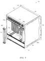
- FIGURE 7 there is a perspective view of a back of the enclosure 700 incorporating a middle stiffening bar 800.
- a middle backplane stiffening bar 800 is provided below with respect to FIGURE 8 after a brief discussion about the various components of the enclosure 700.
- Enclosure 700 includes a frame 701 having a bottom side 702, a top side 704 and two opposite and spaced side walls 706a and 706b.
- the two side walls 706a and 706b extend from the bottom side 702 and the top side 704 to define therebetween an interior space for accommodating the plug-in cards 708 (only one shown) that make-up the industrial computer (not shown).
- the enclosure 700 also supports one or more backplanes 710 (two backplanes 710a and 710b are shown) at the top and bottom of the backplanes 710a and 710b.
- Each backplane 710a and 710b includes a series of connectors 712.
- the plug-in cards 708 depending on their size are designed to slide on one or two guide rails 714 so they can interact with one of the connectors 712 in the backplanes 710a and 710b.
- the plug-in card 708 shown is sized to slide on an upper and lower guide rail 714.
- each backplane 710a and 710b electrically couples a number of the plug-in cards 708 to create the industrial computer.
- plug-in cards 708 including, for example, power cards, processor cards, timing distribution cards and signaling cards.
- the enclosure 700 can also include certain components such as, for example, air ducts 716, a central support bracket (not shown) and various tabs 720 each of which are known in the industry. Therefore, for clarity, the description provided in relation to the enclosure 700 omits the components not necessary to understand the present invention. It should also be understood that the size of the enclosure 700 in the preferred embodiment conforms to the PCI specification, but the enclosure 700 can be any size.
- the middle backplane stiffening bar 800 is used in an enclosure 700 that has two backplanes 710a and 710b.
- the middle backplane stiffening bar 800 is located between and supports two backplanes 710a and 710b (see FIGURES 8B and 8C).
- the middle backplane stiffening bar 800 is preferably constructed from one piece of material and includes a top portion 802, a middle portion 804 and a bottom portion 806.
- the top portion 802 is attached to a bracket 705 extending from the top side 704 (or to the top side 704 itself or to some other support bracket located near the top side 704) of the frame 701 and to the tops of each of the backplanes 710a and 710b (see FIGURES 8B-8E).
- the top portion 802 preferably has a square shape and also has installed therein two captive screws 808.
- the top portion 802 can have a variety of shapes including the "T" shape and could include one or more captive screws 808.
- the two captive screws 808 are used instead of regular nuts and bolts to prevent hardware from falling into the enclosure 700.
- the middle portion 804 has on one side a groove 814 and the other side an extension 816. As illustrated in FIGURES 8B-8E, the groove 814 is configured to receive a side of the backplane 710a, and the extension 816 is configured to be located in back of the other backplane 710b. Essentially, the middle portion 804 and in particular the groove 814 and extension 816 are configured to help support the backplanes 710a and 710b and to help substantially prevent the backplanes 710a and 710b from deflecting when the plug-in card 708 is inserted into or removed from one of the connectors 712 in either of the backplanes 710a and 710b.
- the bottom portion 806 is attached to a bracket 703 extending from the bottom side 702 (or to the bottom side 702 itself or to some other support bracket located near the bottom side 702) of the frame 701 and to the bottoms of each of the backplanes 710a and 710b (see FIGURES 8B-8E).
- the bottom portion 806 preferably has a square shape and also has installed therein two captive screws 812.
- the bottom portion 806 can have a variety of shapes including the "T" shape and could include one or more captive screws 812.
- the two captive screws 812 are used instead of regular nuts and bolts to prevent hardware from falling into the enclosure 700.
- a main feature of the middle backplane stiffening bar 800 is that it enables backplane 710b to be removed from the frame 701 while the other backplane 710a remains operational in the frame 701.
- FIGURE 9 there is a perspective view of the back of an enclosure 900 incorporating the side backplane stiffening bar 400, two backplane stiffening bars 600 and the middle backplane stiffening bar 800.
- the stiffening bars 400, 700 and 900 can be made from a wide variety of materials including, for example, aluminum, plastic or any type of non-conductive material.
- Enclosure 900 includes a frame 901 having a bottom side 902, a top side 904 and two opposite and spaced side walls 906a and 906b.
- the two side walls 906a and 906b extend from the bottom side 902 and the top side 904 to define therebetween an interior space for accommodating the plug-in cards 908 (only one shown) that make-up the industrial computer (not shown).
- the enclosure 900 also supports one or more backplanes 910 (two backplanes 910a and 910b are shown) at the top and bottom of the backplanes 910a and 910b.
- Each backplane 910a and 910b includes a series of connectors 912.
- the plug-in cards 908 depending on their size are designed to slide on one or two guide rails 914 so they can interact with one of the connectors 912 in the backplanes 910a and 910b.
- the plug-in card 908 shown is sized to slide on an upper and lower guide rail 914.
- each backplane 910a and 910b electrically couples a number of the plug-in cards 908 to create the industrial computer.
- plug-in cards 908 including, for example, power cards, processor cards, timing distribution cards and signaling cards.
- the enclosure 900 also includes certain components such as, for example, air ducts 916, a central support bracket (not shown) and various tabs 920 each of which are known in the industry. Therefore, for clarity, the description provided in relation to the enclosure 900 omits the components not necessary to understand the present invention. It should also be understood that the size of the enclosure 900 in the preferred embodiment conforms to the PCI specification, but the enclosure 900 can be any size.
- the enclosure 900 incorporates all three of the aforementioned stiffening bars 400, 600 and 800 to help support the backplanes 910a and 910b and to help substantially prevent the backplanes 910a and 910b from deflecting when one of the plug-in cards 908 are inserted into or removed from one of the connectors 912 in either of the backplanes 910a and 910b.
- the enclosure 900 can incorporate different combinations of the stiffening bars 400, 600 and 800 and still support the backplanes 910a and 910b and still help to substantially prevent the backplanes 910a and 910b from deflecting when one of the plug-in cards 908 is inserted into or removed from one of the connectors 912 in either of the backplanes 910a and 910b.
- the enclosure 900 could incorporate only the side stiffening bar 400 and the middle stiffening bar 800.
- FIGURE 10 there is a flowchart illustrating the basic steps of the preferred method 1000 for supporting one or more backplanes located in an enclosure.
- the description provided below is with reference to the components of enclosure 900. But, it should be understood that the description below could also be written with reference to enclosures 200, 500 or 700.
- each of the backplanes 910a and 910b are installed within and attached to the enclosure 900.
- the tops and bottoms of the backplanes 910a and 910b can be respectively secured to the top side 904 and the bottom side 902 of the enclosure 900.
- one or more of the stiffening bars 400, 600 and/or 800 are attached to the enclosure 900 and the backplanes 910a and 910b.
- the stiffening bar(s) 400, 600 and 800 are attached to the enclosure 900 and the backplanes 910a and 910b in a manner that substantially prevents the backplanes 910a and 910b from deflecting when one of the plug-in cards 908 is inserted into or removed from one of the connectors 912 in either of the backplanes 910a and 910b.
- the enclosures of the present invention are a marked improvement over the traditional enclosure wherein the backplane would deflect when a plug-in card was inserted into a connector or removed from the connector in the backplane.
Landscapes
- Engineering & Computer Science (AREA)
- Microelectronics & Electronic Packaging (AREA)
- Mounting Of Printed Circuit Boards And The Like (AREA)
Abstract
An enclosure and method are described that uses one or more stiffening bars to support one or more backplanes and to help prevent the deflection of the backplane(s) when a plug-in card is inserted into or removed from a connector in one of the backplanes. Three different embodiments of the stiffening bars are described herein including a side backplane stiffening bar, a backplane stiffening bar and a middle backplane stiffening bar. <IMAGE>
Description
The present invention relates in general to electronic
packaging and, in particular, to an enclosure that uses one
or more stiffening bars to support a backplane and to help
prevent the deflection of the backplane when a plug-in card
is inserted into or removed from a connector in the
backplane.
Besides the desktop-sized and notebook-sized personal
computers widely used today in homes, schools and offices,
there are so-called industrial computers that are widely
used in rugged environments such as an industrial
environment and a military environment. Since the
industrial computers operate in rugged environments, the
industrial computers are designed to fit within an
enclosure that is more durable than the enclosures that
contain the desktop-sized and notebook-sized personal
computers. Currently, there are different specifications
and standards for industrial computers and their enclosures
one of which is the Peripheral Component Interconnect (PCI)
specification. The PCI specification describes an enclosure
known as a CompactPCI™ subrack which receives a number of
plug-in cards known as CompactPCI™ boards that make-up the
industrial computer. More details about the CompactPCI™
subrack and the CompactPCI™ boards that make-up the
industrial computer are set forth in the PCI specification
the contents of which are incorporated herein by reference.
Traditional enclosures such as the CompactPCI™ subrack
includes one or more backplanes that have connectors
configured to interface with the plug-in cards (e.g.,
processing cards, signaling cards, power supply cards) that
make-up the industrial computer. Unfortunately, the
CompactPCI™ subrack supports a backplane at the top and
bottom of the backplane which leads to the problematical
situation where the backplane would deflect whenever a
plug-in card is inserted into or removed from a connector
in that backplane. Referring to FIGURES 1A and 1B there are
shown cut-away side views of a traditional CompactPCI™
subrack 100 illustrating how a backplane 102 would deflect
when a plug-in card 104 is inserted into and removed from a
connector 106 in the backplane 102. The deflection of the
backplane 102 can lead to the bending of pins in the
connector 106 which would make it impossible for the plug-in
card 104 to seat properly in the connector 106. Of
course, when the plug-in card 104 does not seat properly in
the connector 106 then that plug-in card 104 and the
industrial computer would not work properly. Accordingly,
there is a need for an enclosure that uses one or more
stiffening bars to support a backplane and to help prevent
the deflection of the backplane when a plug-in card is
inserted into or removed from a connector in the backplane.
This need and other needs are addressed by the enclosure
and method of the present invention.
The present invention includes an enclosure and method
that uses one or more stiffening bars to support one or
more backplanes and to help prevent the deflection of the
backplane(s) when a plug-in card is inserted into or
removed from a connector in one of the backplanes. Three
different embodiments of the stiffening bars are described
herein including a side backplane stiffening bar, a
backplane stiffening bar and a middle backplane stiffening
bar.
A more complete understanding of the present invention
may be had by reference to the following detailed
description when taken in conjunction with the accompanying
drawings wherein:
Referring to FIGURES 2-10, there are disclosed in
accordance with the present invention an enclosure 200,
500, 700 and 900 and preferred method 1000 that uses one or
more stiffening bars 400, 600 and 800 to support two
backplanes and to help prevent the deflection of one of the
backplanes when a plug-in card is inserted into a connector
or removed from the connector in that backplane.
Although the enclosure 200, 500, 700 and 900 is
described as being similar to a CompactPCI™ subrack that is
built in accordance with the Peripheral Component
Interconnect (PCI) Specification, it should be understood
that any type of enclosure incorporating one or more
backplanes can use the stiffening bars 400, 600 and 800 of
the present invention. Accordingly, the enclosure 200, 500,
700 and 900 and the preferred method 1000 should not be
construed in a limited manner.
Referring to FIGURES 2-3, there are respectively shown
perspective views of the front and the back of the
enclosure 200 incorporating a side backplane stiffening bar
400. For clarity, a detailed discussion about the side
stiffening bar 400 is provided below with respect to FIGURE
4 after a brief discussion about the various components of
the enclosure 200.
The enclosure 200 includes a frame 201 having a bottom
side 202, a top side 204 and two opposite and spaced side
walls 206a and 206b. The two side walls 206a and 206b
extend from the bottom side 202 and the top side 204 to
define therebetween an interior space for accommodating the
plug-in cards 208 (only one shown) that make-up the
industrial computer (not shown). The enclosure 200 also
supports one or more backplanes 210 (two backplanes 210a
and 210b are shown) at the top and bottom of the backplanes
210a and 210b. Each backplane 210a and 210b includes a
series of connectors 212. The plug-in cards 208 depending
on their size are designed to slide on one or two guide
rails 214 so they can interact with one of the connectors
212 in the backplanes 210a and 210b. The plug-in card 208
shown is sized to slide on an upper and lower guide rail
214. In operation, each backplane 210a and 210b
electrically couples a number of the plug-in cards 208 to
create the industrial computer. There are a wide variety of
plug-in cards 208 including, for example, power cards,
processor cards, timing distribution cards and signaling
cards.
The enclosure 200 can also include certain components
such as, for example, air ducts 216, a central support
bracket 218 and various tabs 220 each of which are known in
the industry. Therefore, for clarity, the description
provided in relation to the enclosure 200 omits the
components not necessary to understand the present
invention. It should be understood that the size of the
enclosure 200 in the preferred embodiment conforms to the
PCI specification, but the enclosure 200 can be any size.
Referring to FIGURE 4, there is a side view
illustrating in greater detail the side backplane
stiffening bar 400. The side backplane stiffening bar 400
includes a first bar 402 and a second bar 404 (shown as
rectangular bars 402 and 404). The first bar 402 is
attached to one of the side walls 206a of the frame 201 and
is located in front of one of the backplanes 210a (see
FIGURE 2). The second bar 404 is attached to the same side
wall 206a of the frame 201 and is located in back of
backplane 210a (see FIGURE 3). Generally, the first bar 402
and the second bar 404 are attached via screws 406 to the
side wall 206a after the backplane 210a is installed within
the enclosure 200. The first bar 402 and the second bar 404
are also preferably located at the end of the backplane
210a that receives the plug-in card 208 known as the power
card (not shown-but is typically the plug-in card 208
located next to the stiffening bar 400). Thus, the first
bar 402 and the second bar 404 can help support the
backplane 210a and also help to substantially prevent the
backplane 210a from deflecting when the plug-in card 208
(e.g., power card) is inserted into or removed from the
connector 212 in the backplane 210a.
Referring to FIGURE 5, there is a perspective view of
a back of the enclosure 500 incorporating two backplane
stiffening bars 600. For clarity, a detailed discussion
about one of the backplane stiffening bar 600 is provided
below with respect to FIGURE 6 after a brief discussion
about the various components of the enclosure 500.
The enclosure 500 can also include certain components
such as, for example, air ducts 516, a central support
bracket (not shown) and various tabs 520 each of which are
known in the industry. Therefore, for clarity, the
description provided in relation to the enclosure 500 omits
the components not necessary to understand the present
invention. It should also be understood that the size of
the enclosure 500 in the preferred embodiment conforms to
the PCI Specification, but the enclosure 500 can be any
size.
Referring to FIGURES 6A and 6B, there are different
views illustrating in greater detail one of the backplane
stiffening bars 600. The backplane stiffening bar 600 is
preferably constructed from one piece of material and
includes a top portion 602, a middle portion 604 and a
bottom portion 606.
The top portion 602 is attached to a bracket 505
extending from the top side 504 (or to the top side 504
itself or to some other support bracket located near the
top side 504) of the frame 501 and to the top of one of the
backplanes 510a (see FIGURE 6B). As illustrated, the top
portion 602 preferably has the shape of a "T" and also has
installed therein two captive screws 608. However, the top
portion 602 can have a variety of shapes besides the "T"
shape and could include one or more captive screws 608. The
two captive screws 608 are used instead of regular nuts and
bolts to prevent hardware from falling into the enclosure
500.
The middle portion 604 has a front side 610 configured
to be located next to or adjacent to a back of the
backplane 510a. Essentially, the middle portion 604 and the
front side 610 is configured to help support the backplane
510a and to help substantially prevent the backplane 510a
from deflecting when the plug-in card 508 is inserted into
the connector 512 in the backplane 510a.
Like the top portion 602, the bottom portion 606 is
attached to a bracket 503 extending from the bottom side
502 (or to the bottom side 502 itself or to some other
support bracket located near the bottom side 502) of the
frame 501 and to the bottom of one of the backplanes 510b.
As illustrated, the bottom portion 606 preferably has the
shape of a "T" and also has installed therein two captive
screws 612. However, the bottom portion 606 can have a
variety of shapes besides the "T" shape and could include
one or more captive screws 612. The two captive screws 612
are used instead of regular nuts and bolts to prevent
hardware from falling into the enclosure 500.
Referring back to FIGURE 5, the enclosure 500 is shown
to have two backplane stiffening bars 600 that help to
support the backplane 510a and help to substantially
prevent the backplane 510a from deflecting when the plug-in
card 508 is inserted into the connector 512 in the
backplane 510a. However, the enclosure 500 may need only
one backplane stiffening bar 600 or may need several of the
backplane stiffening bars 600 to help support the backplane
510a and to help prevent the backplane 510a from deflecting
when the plug-in card 508 is inserted into the connector
512 in the backplane 510a.
Referring to FIGURE 7, there is a perspective view of
a back of the enclosure 700 incorporating a middle
stiffening bar 800. For clarity, a detailed discussion
about the middle backplane stiffening bar 800 is provided
below with respect to FIGURE 8 after a brief discussion
about the various components of the enclosure 700.
The enclosure 700 can also include certain components
such as, for example, air ducts 716, a central support
bracket (not shown) and various tabs 720 each of which are
known in the industry. Therefore, for clarity, the
description provided in relation to the enclosure 700 omits
the components not necessary to understand the present
invention. It should also be understood that the size of
the enclosure 700 in the preferred embodiment conforms to
the PCI specification, but the enclosure 700 can be any
size.
Referring to FIGURES 8A-8E, there are different views
illustrating in greater detail the middle backplane
stiffening bar 800. The middle backplane stiffening bar 800
is used in an enclosure 700 that has two backplanes 710a
and 710b. In particular, the middle backplane stiffening
bar 800 is located between and supports two backplanes 710a
and 710b (see FIGURES 8B and 8C).
The middle backplane stiffening bar 800 is preferably
constructed from one piece of material and includes a top
portion 802, a middle portion 804 and a bottom portion 806.
The top portion 802 is attached to a bracket 705 extending
from the top side 704 (or to the top side 704 itself or to
some other support bracket located near the top side 704)
of the frame 701 and to the tops of each of the backplanes
710a and 710b (see FIGURES 8B-8E). As illustrated, the top
portion 802 preferably has a square shape and also has
installed therein two captive screws 808. However, the top
portion 802 can have a variety of shapes including the "T"
shape and could include one or more captive screws 808. The
two captive screws 808 are used instead of regular nuts and
bolts to prevent hardware from falling into the enclosure
700.
The middle portion 804 has on one side a groove 814
and the other side an extension 816. As illustrated in
FIGURES 8B-8E, the groove 814 is configured to receive a
side of the backplane 710a, and the extension 816 is
configured to be located in back of the other backplane
710b. Essentially, the middle portion 804 and in particular
the groove 814 and extension 816 are configured to help
support the backplanes 710a and 710b and to help
substantially prevent the backplanes 710a and 710b from
deflecting when the plug-in card 708 is inserted into or
removed from one of the connectors 712 in either of the
backplanes 710a and 710b.
Like the top portion 802, the bottom portion 806 is
attached to a bracket 703 extending from the bottom side
702 (or to the bottom side 702 itself or to some other
support bracket located near the bottom side 702) of the
frame 701 and to the bottoms of each of the backplanes 710a
and 710b (see FIGURES 8B-8E). As illustrated in FIGURE 8A,
the bottom portion 806 preferably has a square shape and
also has installed therein two captive screws 812. However,
the bottom portion 806 can have a variety of shapes
including the "T" shape and could include one or more
captive screws 812. The two captive screws 812 are used
instead of regular nuts and bolts to prevent hardware from
falling into the enclosure 700.
It should be noted that a main feature of the middle
backplane stiffening bar 800 is that it enables backplane
710b to be removed from the frame 701 while the other
backplane 710a remains operational in the frame 701.
Referring to FIGURE 9, there is a perspective view of
the back of an enclosure 900 incorporating the side
backplane stiffening bar 400, two backplane stiffening bars
600 and the middle backplane stiffening bar 800. It should
be understood that the stiffening bars 400, 700 and 900 can
be made from a wide variety of materials including, for
example, aluminum, plastic or any type of non-conductive
material.
The enclosure 900 also includes certain components
such as, for example, air ducts 916, a central support
bracket (not shown) and various tabs 920 each of which are
known in the industry. Therefore, for clarity, the
description provided in relation to the enclosure 900 omits
the components not necessary to understand the present
invention. It should also be understood that the size of
the enclosure 900 in the preferred embodiment conforms to
the PCI specification, but the enclosure 900 can be any
size.
As illustrated, the enclosure 900 incorporates all
three of the aforementioned stiffening bars 400, 600 and
800 to help support the backplanes 910a and 910b and to
help substantially prevent the backplanes 910a and 910b
from deflecting when one of the plug-in cards 908 are
inserted into or removed from one of the connectors 912 in
either of the backplanes 910a and 910b. However, it should
be understood that the enclosure 900 can incorporate
different combinations of the stiffening bars 400, 600 and
800 and still support the backplanes 910a and 910b and
still help to substantially prevent the backplanes 910a and
910b from deflecting when one of the plug-in cards 908 is
inserted into or removed from one of the connectors 912 in
either of the backplanes 910a and 910b. For example, the
enclosure 900 could incorporate only the side stiffening
bar 400 and the middle stiffening bar 800.
Referring to FIGURE 10, there is a flowchart
illustrating the basic steps of the preferred method 1000
for supporting one or more backplanes located in an
enclosure. For clarity, the description provided below is
with reference to the components of enclosure 900. But, it
should be understood that the description below could also
be written with reference to enclosures 200, 500 or 700.
Beginning at step 1002 and assuming the frame 901 has
already been assembled, each of the backplanes 910a and
910b are installed within and attached to the enclosure
900. For example, the tops and bottoms of the backplanes
910a and 910b can be respectively secured to the top side
904 and the bottom side 902 of the enclosure 900. Lastly,
at step 1004, one or more of the stiffening bars 400, 600
and/or 800 are attached to the enclosure 900 and the
backplanes 910a and 910b. The stiffening bar(s) 400, 600
and 800 are attached to the enclosure 900 and the
backplanes 910a and 910b in a manner that substantially
prevents the backplanes 910a and 910b from deflecting when
one of the plug-in cards 908 is inserted into or removed
from one of the connectors 912 in either of the backplanes
910a and 910b.
From the foregoing, it can be readily appreciated by
those skilled in the art that the enclosures of the present
invention are a marked improvement over the traditional
enclosure wherein the backplane would deflect when a plug-in
card was inserted into a connector or removed from the
connector in the backplane.
Although several embodiments of the present invention
have been illustrated in the accompanying Drawings and
described in the foregoing Detailed Description, it should
be understood that the invention is not limited to the
embodiments disclosed, but is capable of numerous
rearrangements, modifications and substitutions without
departing from the spirit of the invention as set forth and
defined by the following claims.
Claims (25)
- An enclosure, comprising:a frame capable of supporting at least one backplane; andat least one stiffening bar attached to said frame in a manner to substantially prevent the at least one backplane from deflecting when a plug-in card is inserted into a connector or removed from the connector in the at least one backplane.
- The enclosure of Claim 1, wherein said at least one stiffening bar includes a side backplane stiffening bar comprising:a first bar attached to a side wall of said frame and located in front of the first backplane; anda second bar attached to the side wall of said frame and located in back of the first backplane.
- The enclosure of Claim 1, wherein said at least one stiffening bar includes a backplane stiffening bar comprising:a top portion attached to a top side of said frame;a middle portion located next to a back of the first backplane; anda bottom portion attached to a bottom side of said frame.
- The enclosure of Claim 3, wherein a plurality of said backplane stiffening bars are used support the backplane.
- The enclosure of Claim 3, wherein said backplane stiffening bar further includes a plurality of captive fasteners used to connect the top portion and the bottom portion to the frame.
- The enclosure of Claim 1, wherein said at least one stiffening bar includes a middle backplane stiffening bar comprising:a top portion attached to a top side of said frame;a middle portion including:a groove in which there is received a side of the first backplane; andan extension located next to a back of the second backplane; anda bottom portion attached to a bottom side of said frame.
- The enclosure of Claim 6, wherein said middle backplane stiffening bar further includes a plurality of captive fasteners used to connect the top portion and the bottom portion to the frame.
- The enclosure of Claim 6, wherein said middle backplane stiffening bar enables the first backplane to be removed from said frame while the second backplane remains operational in said frame.
- The enclosure of Claim 1, wherein said enclosure is an enhanced CompactPCI subrack.
- A method for supporting at least one backplane located in an enclosure, said method comprising the steps of:attaching the at least one backplane to said enclosure; andattaching at least one stiffening bar to said enclosure in a manner to substantially prevent the at least one backplane from deflecting when a plug-in card is inserted into a connector or removed from the connector in the at least one backplane.
- The method of Claim 10, wherein said step of attaching at least one stiffening bar further includes attaching a side backplane stiffening bar to said enclosure, said side backplane stiffening bar comprising:a first bar attached to a side wall of said enclosure and located in front of the first backplane; anda second bar attached to the side wall of said enclosure and located in back of the first backplane.
- The method of Claim 10, wherein said step of attaching at least one stiffening bar further includes attaching a backplane stiffening bar to said enclosure, said backplane stiffening bar comprising:a top portion attached to a top side of said enclosure;a middle portion located next to a back of the first backplane; anda bottom portion attached to a bottom side of said enclosure.
- The method of Claim 12, wherein a plurality of said backplane stiffening bars are used support the backplane.
- The method of Claim 12, wherein said backplane stiffening bar further includes a plurality of captive fasteners used to connect the top portion and the bottom portion to said enclosure.
- The method of Claim 10, wherein said step of attaching at least one stiffening bar further includes attaching a middle backplane stiffening bar to said enclosure, said middle backplane stiffening bar comprising:a top portion attached to said enclosure;a middle portion including:a groove in which there is received a side of the first backplane; andan extension located next to a back of the second backplane; anda bottom portion attached to said enclosure.
- The method of Claim 15, wherein said middle backplane stiffening bar further includes a plurality of captive fasteners used to connect the top portion and the bottom portion to said enclosure.
- The method of Claim 15, wherein said middle backplane stiffening bar enables the first backplane to be removed from said enclosure while the second backplane remains operational in said enclosure.
- The method of Claim 10, wherein said enclosure is an enhanced CompactPCI subrack.
- A side backplane stiffening bar used to support and substantially prevent the deflection of a backplane in an enclosure when a plug-in card is inserted into or removed from the connector in the backplane, said side back plane stiffening bar comprising:a first bar attached to a side wall of said enclosure and located in front of the backplane; anda second bar attached to the side wall of said enclosure and located in back of the backplane.
- A backplane stiffening bar used to support and substantially prevent the deflection of a backplane in an enclosure when a plug-in card is inserted into a connector in the backplane, said backplane stiffening bar comprising:a top portion attached to a top side of said enclosure;a middle portion located next to a back of the backplane; anda bottom portion attached to a bottom side of said enclosure.
- The backplane stiffening bar of Claim 20, wherein a plurality of said backplane stiffening bars are used support the backplane.
- The backplane stiffening bar of Claim 20, further includes a plurality of captive fasteners used to connect the top portion and the bottom portion to said enclosure.
- A middle backplane stiffening bar used to support and substantially prevent the deflection of a first backplane and a second backplane in an enclosure when a plug-in card is inserted into or removed from a connector in either the first backplane and the second backplane, said middle backplane stiffening bar comprising:a top portion attached to a top side of said enclosure;a middle portion including:a groove in which there is received a side of the first backplane; andan extension located next to a back of the second backplane; anda bottom portion attached to a bottom side of said enclosure.
- The middle backplane stiffening bar of Claim 23, further comprising a plurality of captive fasteners used to connect the top portion and the bottom portion to the enclosure.
- The middle backplane stiffening bar of Claim 23, wherein said middle backplane stiffening bar enables the first backplane to be removed from said enclosure while the second backplane remains operational in said enclosure.
Applications Claiming Priority (2)
| Application Number | Priority Date | Filing Date | Title |
|---|---|---|---|
| US7879802A | 2002-02-19 | 2002-02-19 | |
| US78798 | 2002-02-19 |
Publications (1)
| Publication Number | Publication Date |
|---|---|
| EP1337137A1 true EP1337137A1 (en) | 2003-08-20 |
Family
ID=27622803
Family Applications (1)
| Application Number | Title | Priority Date | Filing Date |
|---|---|---|---|
| EP03001207A Withdrawn EP1337137A1 (en) | 2002-02-19 | 2003-01-17 | Enclosure incorporating stiffening bars to support one or more backplanes |
Country Status (1)
| Country | Link |
|---|---|
| EP (1) | EP1337137A1 (en) |
Cited By (1)
| Publication number | Priority date | Publication date | Assignee | Title |
|---|---|---|---|---|
| US10830460B2 (en) | 2018-08-21 | 2020-11-10 | Johnson Controls Technology Company | HVAC access panel latch systems and methods |
Citations (2)
| Publication number | Priority date | Publication date | Assignee | Title |
|---|---|---|---|---|
| US6084182A (en) * | 1997-04-07 | 2000-07-04 | Hybricon Corporation | Backplane stiffener |
| US6324065B1 (en) * | 1999-03-31 | 2001-11-27 | Emc Corporation | Stiffener for a printed circuit board |
-
2003
- 2003-01-17 EP EP03001207A patent/EP1337137A1/en not_active Withdrawn
Patent Citations (2)
| Publication number | Priority date | Publication date | Assignee | Title |
|---|---|---|---|---|
| US6084182A (en) * | 1997-04-07 | 2000-07-04 | Hybricon Corporation | Backplane stiffener |
| US6324065B1 (en) * | 1999-03-31 | 2001-11-27 | Emc Corporation | Stiffener for a printed circuit board |
Cited By (1)
| Publication number | Priority date | Publication date | Assignee | Title |
|---|---|---|---|---|
| US10830460B2 (en) | 2018-08-21 | 2020-11-10 | Johnson Controls Technology Company | HVAC access panel latch systems and methods |
Similar Documents
| Publication | Publication Date | Title |
|---|---|---|
| US10359815B1 (en) | Adaptable storage bay for solid state drives | |
| US5519573A (en) | I/O riser card for motherboard in a personal computer/server | |
| US6208522B1 (en) | Computer chassis assembly with a single center pluggable midplane board | |
| US4971563A (en) | Modular backplane assemblies for computers | |
| US20060274508A1 (en) | Computer rack mounting system | |
| US6247078B1 (en) | Computer interface for integrating a first computer into a second computer | |
| US20150351233A1 (en) | Flexible Midplane And Architecture For A Multi-Processor Computer System | |
| US7359216B2 (en) | Small-frame computer with overlapping add-in cards | |
| US8472204B2 (en) | Advanced mezzanine card for hosting a PMC or XMC | |
| US10165702B2 (en) | Open chassis and server module incorporating the same | |
| US7751200B2 (en) | Display apparatus | |
| US7361043B2 (en) | Apparatus including card element, device inserted into apparatus and a method for connecting or disconnecting the card element | |
| US6094358A (en) | Card stiffener optimized for connector engagement | |
| US20170086324A1 (en) | System and method for housing circuit boards of different physical dimensions | |
| US20080180929A1 (en) | System having primary and secondary backplanes | |
| DE60225393T2 (en) | Instrument with a recess for connectors in the housing | |
| DE102022127438B4 (en) | Cable jaws for stacked HBAs with bracket-mounted connectors | |
| US20160381825A1 (en) | Multiple graphics processing unit platform | |
| JP6717987B2 (en) | Server system | |
| US20110096484A1 (en) | Layout structure of server chassis | |
| US5785533A (en) | Termination panel for control unit | |
| JPH03151695A (en) | Supporting device of planer board and its supporting method | |
| US6608761B2 (en) | Multiple processor cards accessing common peripherals via transparent and non-transparent bridges | |
| EP1337137A1 (en) | Enclosure incorporating stiffening bars to support one or more backplanes | |
| US4896248A (en) | Module frame for receiving insertable electrical printed circuit boards |
Legal Events
| Date | Code | Title | Description |
|---|---|---|---|
| PUAI | Public reference made under article 153(3) epc to a published international application that has entered the european phase |
Free format text: ORIGINAL CODE: 0009012 |
|
| AK | Designated contracting states |
Designated state(s): AT BE BG CH CY CZ DE DK EE ES FI FR GB GR HU IE IT LI LU MC NL PT SE SI SK TR |
|
| AX | Request for extension of the european patent |
Extension state: AL LT LV MK RO |
|
| AKX | Designation fees paid | ||
| REG | Reference to a national code |
Ref country code: DE Ref legal event code: 8566 |
|
| STAA | Information on the status of an ep patent application or granted ep patent |
Free format text: STATUS: THE APPLICATION IS DEEMED TO BE WITHDRAWN |
|
| 18D | Application deemed to be withdrawn |
Effective date: 20040221 |