EP1337085A2 - Reduction of interference between subcarriers in multicarrier communication systems - Google Patents
Reduction of interference between subcarriers in multicarrier communication systems Download PDFInfo
- Publication number
- EP1337085A2 EP1337085A2 EP20030003061 EP03003061A EP1337085A2 EP 1337085 A2 EP1337085 A2 EP 1337085A2 EP 20030003061 EP20030003061 EP 20030003061 EP 03003061 A EP03003061 A EP 03003061A EP 1337085 A2 EP1337085 A2 EP 1337085A2
- Authority
- EP
- European Patent Office
- Prior art keywords
- signals
- subcarriers
- interference
- subcarrier
- multicarrier communication
- Prior art date
- Legal status (The legal status is an assumption and is not a legal conclusion. Google has not performed a legal analysis and makes no representation as to the accuracy of the status listed.)
- Withdrawn
Links
Images





Classifications
-
- H—ELECTRICITY
- H04—ELECTRIC COMMUNICATION TECHNIQUE
- H04L—TRANSMISSION OF DIGITAL INFORMATION, e.g. TELEGRAPHIC COMMUNICATION
- H04L27/00—Modulated-carrier systems
- H04L27/26—Systems using multi-frequency codes
- H04L27/2601—Multicarrier modulation systems
- H04L27/2647—Arrangements specific to the receiver only
Definitions
- the present invention relates to a method of reducing inter-subcarrier interference in multicarrier communication systems and a receiver using it, and more particularly to a receiver for use in multicarrier communication systems to suppress inter-subcarrier interference.
- a conventional transmitter for use in multicarrier communication systems is configured of an encoder 31, a demultiplexer 32, lowpass filters (LPFs) 33 and 34, digital-to-analog (D/A) converters 35 and 36, multipliers 37 and 38, a synthesizer 39, a transmitting amplifier 40 and a transmitting antenna 41 as shown in Fig. 2.
- LPFs lowpass filters
- D/A digital-to-analog converters
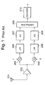
- a receiver for use in multicarrier communication systems is configured of a receiving antenna 201, a receiving amplifier 202, multipliers 203 and 204, lowpass filters (LPFs) 205 and 206, analog-to-digital (A/D) converters 207 and 208, a multiplexer 209 and a decoder 210 as shown in Fig. 1.
- the transmitter and the receiver mentioned above are supposed to use two subcarriers.
- input signals are encoded by the encoder 31, and demultiplexed by the demultiplexer 32 into two sequences.
- Each of the sequences into which the signals have been demultiplexed by the demultiplexer 32 is bandwidth-limited by the lowpass filters 33 and 34.
- the signals bandwidth-limited by the lowpass filters 33 and 34 are converted into analog signals by the D/A converters 35 and 36, and modulated by the multipliers 37 and 38 with respect to subcarriers.
- the signals modulated with respect to the subcarriers are mixed by the synthesizer 39, amplified by the transmitting amplifier 40, and transmitted from the transmitting antenna 41.
- receive signals received by the receiving antenna 201 are amplified by the receiving amplifier 202, subjected to quadrature demodulation by the multipliers 203 and 204 with respect to the respective subcarriers, and band-limited by the lowpass filters 205 and 206.
- the receive signals band-limited by the lowpass filters 205 and 206 are converted into digital signals by the A/D converters 207 and 208 at a sampling frequency fs.
- the receive signals converted into digital signals are multiplexed into a single sequence by the multiplexer 209, and decoded by the decoder 210 into output signals.
- the frequency band of each subcarrier is limited by the lowpass filters 33 and 34, and sufficient frequency spacing is ensured between the subcarriers to prevent the frequency bands of the subcarriers from overlapping each other or, in the orthogonal frequency division multiplexing (OFDM) system, the frequency bands of subcarriers are allowed to overlap each other by using mutually orthogonal subcarriers.
- OFDM orthogonal frequency division multiplexing
- the band limiting filters should have sufficient attenuation characteristic outside the bands, and the spacing between the subcarriers should be sufficiently wide.
- the orthogonality cannot be maintained once waveforms are distorted on multiple paths, inviting signal interference between the subcarriers.
- An object of the present invention is to provide a method of reducing inter-subcarrier interference in multicarrier communication systems capable of reducing inter-subcarrier interfering signals and a receiver using it.
- the fixed portion of the interference characteristic is figured out with respect to demodulated signals of each subcarrier by compensating for variations over time of phase components of the interfering signals between the subcarriers according to the ratio between the frequency difference between the subcarriers and the receive sampling frequency, the values of the interfering signals between the subcarriers are estimated by multiplying the fixed portion of the interference characteristic by the equivalent to the variations over time, and the estimated values of the interfering signals are subtracted from the demodulated signals of the subcarriers.
- a receiver of a multicarrier communication system is configured of:
- the receiver of the multicarrier communication system is characteristic in that it is provided with an interfering signal reducer for reducing inter-subcarrier interfering signals with respect to digital signals of the subcarriers.
- This interfering signal reducer performs processing to cancel interfering signals leaking from one adjacent subcarrier to another. Therefore, it is made possible to improve the reception quality on each subcarrier.
- the receiver of the multicarrier communication system provides an advantage that interfering signals between subcarriers can be reduced by estimating interfering signals between subcarriers with respect to demodulated signals of each subcarrier and subtracting the interfering signals from the demodulated signals of the subcarrier
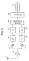
- Fig. 3 is a block diagram illustrating the configuration of a receiver in a multicarrier communication system, which is a preferred embodiment of the invention.
- the receiver of the multicarrier communication system consists of a receiving antenna 11, a receiving amplifier 12, multipliers 13 and 14, lowpass filters (LPFs) 15 and 16, A/D (analog/digital) converters 17 and 18, an interference reducer 19, a multiplexer 20 and a decoder 21.
- LPFs lowpass filters
- A/D (analog/digital) converters 17 and 18 an interference reducer 19
- the receiver of the multicarrier communication system which is a preferred embodiment of the present invention, has a configuration comprising the conventional receiver shown in Fig. 1 plus the interference reducer 19.
- signals received by the receiving antenna 11 are amplified by the receiving amplifier 12, subjected to quadrature demodulation by the multipliers 13 and 14 with respect to the respective subcarriers, and band-limited by the lowpass filters 15 and 16.
- the signals band-limited by the lowpass filters 15 and 16 are respectively converted by the A/D converters 17 and 18 into digital signals at the sampling frequency fs.
- the receive signals converted into digital signals, after interfering signals among them are reduced by the interference reducer 19, are multiplexed into a single sequence by the multiplexer 20, and decoded by the decoder 21 into output signals.
- the interference reducer 19 using the signals of the subcarriers having undergone A/D conversion by the A/D converters 17 and 18, improves the reception quality by estimating and canceling interfering signals leaking between the subcarriers.
- Fig. 2 is a block diagram illustrating the configuration of the transmitter of a conventional multicarrier communication system.
- the transmitter of the multicarrier communication system consists of an encoder 31, a demultiplexer 32, lowpass filters (LPFs) 33 and 34, digital/analog (D/A) converters 35 and 36, multipliers 37 and 38, a synthesizer 39, a transmitting amplifier 40 and a transmitting antenna 41.
- LPFs lowpass filters
- D/A digital/analog
- input signals are encoded by the encoder 31 and demultiplexed by the demultiplexer 32 into two sequences.
- the sequences into which the signals have been demultiplexed by the demultiplexer 32 are band-limited by the lowpass filters 33 and 34.
- the signals band-limited by the lowpass filters 33 and 34 are converted into analog signals by the D/A converters 35 and 36 and modulated by the multipliers 37 and 38 with respect to the subcarriers.
- the signals modulated with respect to the subcarriers are mixed by the synthesizer 39, amplified by the transmitting amplifier 40, and transmitted from the transmitting antenna 41.
- Fig. 4 is a block diagram illustrating the configuration of the interference reducer 19 in Fig. 3.
- the interference reducer 19 consists of an interference quantity calculator 19a, complex multipliers 19b and 19c, and subtractors 19d and 19e.
- the interference quantity calculator 19a calculates or estimates the amplitudes and phase quantities of interfering signals leaking from a subcarrier 1 (f1) into a subcarrier 2 (f2), and notifies the complex multiplier 19b of its findings.
- demodulated signals of the subcarrier 1 are multiplied by the amplitudes and phase quantities of the interfering signals notified from the interference quantity calculator 19a, and supplies the products to the subtractor 19d.
- the subtractor 19d subtracts the output of the multiplier 19b from the signals of the subcarrier 2 and supplies the differences.
- the interference quantity calculator 19a calculates or estimates the amplitudes and phase quantities of interfering signals leaking from the subcarrier 2 into the subcarrier 1, and the complex multiplier 19c multiplies the demodulated signals of the subcarrier 2 by the amplitudes and phase quantities of the interfering signals notified from the interference quantity calculator 19a, and the subtractor 19e subtracts the output of the multiplier 19c from the demodulated signals of the subcarrier 1.
- Fig. 5 shows frequency bands in a multicarrier communication system using two subcarriers
- Fig. 6 is a diagram for describing the phase rotation of interfering signals between subcarriers
- Fig. 7 is a diagram for describing the phase rotation of interfering signals whose receive sampling frequency is twice the frequency difference between subcarriers.
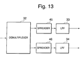
- Fig. 13 is a block diagram illustrating the inserting position of the spreading means of the transmitter where the multicarrier communication system is a multicarrier/direct sequence code division multiple access system
- Fig. 14 is a block diagram illustrating the inserting position of the despreading-RAKE synthesizing means of the receiver where the multicarrier communication system is a multicarrier/direct sequence code division multiple access system.
- the amplitude characteristic of interference can be measured from the leakage of signals of a known series inserted into the signals of each subcarrier as pilot signals.
- the interference quantity calculator 19a measures the amplitudes of pilot signals of the subcarrier 1 leaking into the subcarrier 2.
- phase characteristic can also be measured at the same time, as the phase characteristic rotates with the lapse of time as shown in Fig. 6 correspondingly to the relationship between the frequency difference between subcarriers and the sampling frequency, the calculation should take this factor into consideration.
- the interference quantity calculator 19a measures the fixed portion of the phase characteristic net of variations over time, and adds the variations over time to the fixed portion in its output to the multiplier 19b.
- d1(n)* representing the complex conjugate of d1(n):
- p1(n) ⁇ d1 (n) * h1 ⁇
- the influence of the second term can be reduced, and the transmission path characteristic coefficient h1 can be figured out from the first term.
- the transmission path characteristic coefficient h2 can be figured out from p2(n) ⁇ d2(n)* in a similar way.
- the transmission path characteristic coefficients so figured will be expressed as h1" and h2", respectively.
- the influence of the first term can be reduced, and the leak characteristic coefficient a1 can be figured out from the second term.
- the leak characteristic coefficient a2 can be figured out in a similar way.
- the interference quantity calculator 19a supplies the multiplier 19b with a2"/h1" ⁇ exp(j2n ⁇ (f1 - f2) /fs) and the multiplier 19c with a1"/h2" ⁇ exp(j2n ⁇ (f2 - f1)/fs).
- the interference quantity can be reduced from the original interference quantity +a1 ⁇ d2(n) ⁇ exp(j2n ⁇ (f2 - f1)/fs). Similarly, the interference quantity can be reduced for the output signal of the subtractor 19e.
- the multicarrier communication system is a multicarrier/direct sequence code division multiple access system
- the signals of the subcarriers which are the output of the demultiplexer 32, are spread by spreaders 45 and 46 as shown in Fig. 13, and in the receiver despreading-RAKE synthesizers 25 and 26 perform despreading-RAKE syntheses at a stage preceding the multiplexer 20 as shown in Fig. 14.
- the pilot signals may be either time-multiplexed or code-multiplexed with data.
- Fig. 8 is a block diagram illustrating the configuration of the receiver of the multicarrier communication system, which is another preferred embodiment of the invention.
- the receiver of the multicarrier communication system shown in Fig. 8 has a configuration for three subcarriers, and this configuration is the same as the receiver of the multicarrier communication system in the earlier described embodiment shown in Fig. 3 except that there are added a multiplier 22, a lowpass filter 23 and an A/D converter 24.
- the same constituent elements as in Fig. 3 are denoted by respectively the same reference signs.
- interfering signals among three subcarriers are reduced by the interference reducer 19.
- Fig. 9 is a block diagram illustrating the configuration of the transmitter of the multicarrier communication system, which matches the other preferred embodiment of the invention.
- the transmitter of the multicarrier communication system shown in Fig. 9 has a configuration for three subcarriers, and this configuration is the same as the transmitter of the multicarrier communication system in the earlier described embodiment shown in Fig. 2 except that there are added a lowpass filter 42, a D/A converter 43 and a multiplier 44.
- the same constituent elements as in Fig. 2 are denoted by respectively the same reference signs.
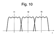
- Fig. 10 shows the frequency bands of the three subcarriers in the other preferred embodiment of the invention
- Fig. 11 is a block diagram illustrating the configuration of the interference reducer 19 in Fig. 8.
- the interference reducer 19 in Fig. 11 has a configuration in which the number of subcarriers is increased to three, and this configuration is the same as the interference reducer 19 shown in Fig. 4 except that there are added interference quantity calculators 19f and 19j, complex multipliers 19g, 19h, 19k and 19l and a subtractor 19i.
- the same constituent elements as in Fig. 4 are denoted by respectively the same reference signs.
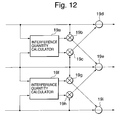
- Fig. 12 is another block diagram illustrating the configuration of the interference reducer 19 in Fig. 8.
- Fig. 12 shows a case in which the leaks between the subcarrier 1 and the subcarrier 3 are sufficiently small, and in this case it is possible to dispense with processing to reduce interference between the subcarrier 1 and the subcarrier 3.
- the interference reducer 19 in Fig. 12 has a configuration in which the number of subcarriers is increased to three as in Fig. 11, and this configuration is the same as the interference reducer 19 shown in Fig. 11 except that there are added an interference quantity calculator 19j and complex multipliers 19k and 19l.
- the same constituent elements as in Fig. 11 are denoted by respectively the same reference signs.
- interfering signals between subcarriers can be reduced by estimating and subtracting interfering signals leaking from one subcarrier to another in the receive digital signals of the subcarrier, and the quality of reception can be thereby improved.
Landscapes
- Engineering & Computer Science (AREA)
- Computer Networks & Wireless Communication (AREA)
- Signal Processing (AREA)
- Noise Elimination (AREA)
- Digital Transmission Methods That Use Modulated Carrier Waves (AREA)
- Cable Transmission Systems, Equalization Of Radio And Reduction Of Echo (AREA)
Abstract
A receiver of a multicarrier communication system capable of
reducing inter-subcarrier interfering signals is to be
provided. Receive signals received by a receiving antenna (11;
211) are amplified by a receiving amplifier (12; 202),
subjected to quadrature demodulation by multipliers (13, 14,
22; 203, 204) with respect to the respective subcarriers, and
band-limited by lowpass filters (15, 16, 23; 205, 206). The
signals band-limited by the lowpass filters (15, 16, 23; 205,
206) are converted into digital signals by A/D converters (17,
18, 24; 207, 208) at a sampling frequency fs. With respect to
the receive signals converted into digital signals,
interfering signals leaking between subcarriers are estimated
by using A/D converted by the A/D converters (17, 18, 24; 207,
208) and are canceled. The receive signals reduced in
interfering signals are multiplexed into a single sequence by
a multiplexer 20; 209), and decoded by a decoder (21, 210)
into output signals.
Description
- The present invention relates to a method of reducing inter-subcarrier interference in multicarrier communication systems and a receiver using it, and more particularly to a receiver for use in multicarrier communication systems to suppress inter-subcarrier interference.
- A conventional transmitter for use in multicarrier communication systems is configured of an
encoder 31, ademultiplexer 32, lowpass filters (LPFs) 33 and 34, digital-to-analog (D/A)converters multipliers synthesizer 39, a transmittingamplifier 40 and a transmittingantenna 41 as shown in Fig. 2. - A receiver for use in multicarrier communication systems is configured of a receiving
antenna 201, areceiving amplifier 202,multipliers converters multiplexer 209 and adecoder 210 as shown in Fig. 1. The transmitter and the receiver mentioned above are supposed to use two subcarriers. - First in the transmitter, input signals are encoded by the
encoder 31, and demultiplexed by thedemultiplexer 32 into two sequences. Each of the sequences into which the signals have been demultiplexed by thedemultiplexer 32 is bandwidth-limited by thelowpass filters - The signals bandwidth-limited by the
lowpass filters A converters multipliers synthesizer 39, amplified by the transmittingamplifier 40, and transmitted from the transmittingantenna 41. - On the other hand in the receiver, receive signals received by the receiving
antenna 201 are amplified by the receivingamplifier 202, subjected to quadrature demodulation by themultipliers lowpass filters - The receive signals band-limited by the
lowpass filters D converters multiplexer 209, and decoded by thedecoder 210 into output signals. - In the multicarrier communication system, to prevent signal interference between subcarriers, the frequency band of each subcarrier is limited by the
lowpass filters - However, in the receiver of the conventional multicarrier communication system described above, if the frequency bands of subcarriers overlap each other as shown in Fig. 5, signal interference occurs between the subcarriers, inviting a deterioration in reception performance.
- Therefore, in the receiver of the conventional multicarrier communication system, the band limiting filters should have sufficient attenuation characteristic outside the bands, and the spacing between the subcarriers should be sufficiently wide.
- Or in the OFDM system referred to above, as it uses mutually orthogonal subcarriers, the orthogonality cannot be maintained once waveforms are distorted on multiple paths, inviting signal interference between the subcarriers.
- An object of the present invention is to provide a method of reducing inter-subcarrier interference in multicarrier communication systems capable of reducing inter-subcarrier interfering signals and a receiver using it.
- By a method of reducing inter-subcarrier interference in multicarrier communication systems according to the invention, the fixed portion of the interference characteristic is figured out with respect to demodulated signals of each subcarrier by compensating for variations over time of phase components of the interfering signals between the subcarriers according to the ratio between the frequency difference between the subcarriers and the receive sampling frequency, the values of the interfering signals between the subcarriers are estimated by multiplying the fixed portion of the interference characteristic by the equivalent to the variations over time, and the estimated values of the interfering signals are subtracted from the demodulated signals of the subcarriers.
- A receiver of a multicarrier communication system according to the invention is configured of:
- a means of estimating from demodulated signals of each
of the subcarriers interfering signals between the subcarriers,
and a means of subtracting the interfering signals from the
demodulated signals of the subcarriers, wherein:
- the means of estimating the interfering signals estimates the values of the interfering signals by figuring out the fixed portion of the interference characteristic by compensating for variations over time of phase components of the interfering signals according to the ratio between the frequency difference between the subcarriers and the receive sampling frequency, and multiplying the fixed portion of the interference characteristic by the equivalent to the variations over time.
-
- Thus, the receiver of the multicarrier communication system according to the invention is characteristic in that it is provided with an interfering signal reducer for reducing inter-subcarrier interfering signals with respect to digital signals of the subcarriers.
- This interfering signal reducer performs processing to cancel interfering signals leaking from one adjacent subcarrier to another. Therefore, it is made possible to improve the reception quality on each subcarrier.
- As hitherto described, the receiver of the multicarrier communication system according to the invention provides an advantage that interfering signals between subcarriers can be reduced by estimating interfering signals between subcarriers with respect to demodulated signals of each subcarrier and subtracting the interfering signals from the demodulated signals of the subcarrier
-
- Fig. 1 is a block diagram illustrating the configuration of a receiver in a conventional multicarrier communication system.
- Fig. 2 is a block diagram illustrating the configuration of a transmitter in the conventional multicarrier communication system.
- Fig. 3 is a block diagram illustrating the configuration of a receiver in a multicarrier communication system, which is a preferred embodiment of the invention.
- Fig. 4 is a block diagram illustrating the configuration of an interference reducer in Fig. 3.
- Fig. 5 shows frequency bands in a multicarrier communication system using two subcarriers.
- Fig. 6 is a diagram for describing the phase rotation of interfering signals between subcarriers.
- Fig. 7 is a diagram for describing the phase rotation of interfering signals whose receive sampling frequency is twice the frequency difference between subcarriers.
- Fig. 8 is a block diagram illustrating the configuration of a receiver in a multicarrier communication system, which is another preferred embodiment of the invention.
- Fig. 9 is a block diagram illustrating the configuration of a transmitter in a conventional multicarrier communication system with three subcarriers.
- Fig. 10 shows frequency bands in a multicarrier communication system using three subcarriers.
- Fig. 11 is a block diagram illustrating the configuration of an interference reducer in Fig. 8.
- Fig. 12 is another block diagram illustrating the configuration of an interference reducer in Fig. 8.
- Fig. 13 is a block diagram illustrating the inserting position of the spreading means of the transmitter where the multicarrier communication system is a multicarrier/direct sequence code division multiple access system.
- Fig. 14 is a block diagram illustrating the inserting position of the despreading-RAKE synthesizing means of the receiver where the multicarrier communication system is a multicarrier/direct sequence code division multiple access system.
-
- Preferred embodiments of the present invention will be described below with reference to accompanying drawings.
- Fig. 3 is a block diagram illustrating the configuration of a receiver in a multicarrier communication system, which is a preferred embodiment of the invention. Referring to Fig. 3, the receiver of the multicarrier communication system consists of a receiving
antenna 11, areceiving amplifier 12,multipliers converters multiplexer 20 and adecoder 21. Thus, the receiver of the multicarrier communication system, which is a preferred embodiment of the present invention, has a configuration comprising the conventional receiver shown in Fig. 1 plus theinterference reducer 19. - In the receiver, signals received by the
receiving antenna 11 are amplified by thereceiving amplifier 12, subjected to quadrature demodulation by themultipliers lowpass filters - The signals band-limited by the
lowpass filters D converters interference reducer 19, are multiplexed into a single sequence by themultiplexer 20, and decoded by thedecoder 21 into output signals. - Thus the interference reducer 19, using the signals of the subcarriers having undergone A/D conversion by the A/
D converters - Fig. 2 is a block diagram illustrating the configuration of the transmitter of a conventional multicarrier communication system. Referring to Fig. 2, the transmitter of the multicarrier communication system consists of an
encoder 31, ademultiplexer 32, lowpass filters (LPFs) 33 and 34, digital/analog (D/A)converters multipliers synthesizer 39, a transmittingamplifier 40 and a transmittingantenna 41. - In the transmitter, input signals are encoded by the
encoder 31 and demultiplexed by thedemultiplexer 32 into two sequences. The sequences into which the signals have been demultiplexed by thedemultiplexer 32 are band-limited by thelowpass filters - The signals band-limited by the
lowpass filters A converters multipliers synthesizer 39, amplified by the transmittingamplifier 40, and transmitted from the transmittingantenna 41. - Fig. 4 is a block diagram illustrating the configuration of the
interference reducer 19 in Fig. 3. Referring to Fig. 4, theinterference reducer 19 consists of aninterference quantity calculator 19a,complex multipliers subtractors - In the interference reducer 19, two-component (I/Q) signals having undergone quadrature demodulation are flowing on each signal line, and they are expressed in complex numbers. The
interference quantity calculator 19a calculates or estimates the amplitudes and phase quantities of interfering signals leaking from a subcarrier 1 (f1) into a subcarrier 2 (f2), and notifies thecomplex multiplier 19b of its findings. - In the
complex multiplier 19b, demodulated signals of thesubcarrier 1 are multiplied by the amplitudes and phase quantities of the interfering signals notified from theinterference quantity calculator 19a, and supplies the products to thesubtractor 19d. Thesubtractor 19d subtracts the output of themultiplier 19b from the signals of the subcarrier 2 and supplies the differences. - Similarly, the
interference quantity calculator 19a calculates or estimates the amplitudes and phase quantities of interfering signals leaking from the subcarrier 2 into thesubcarrier 1, and thecomplex multiplier 19c multiplies the demodulated signals of the subcarrier 2 by the amplitudes and phase quantities of the interfering signals notified from theinterference quantity calculator 19a, and thesubtractor 19e subtracts the output of themultiplier 19c from the demodulated signals of thesubcarrier 1. - Fig. 5 shows frequency bands in a multicarrier communication system using two subcarriers, Fig. 6 is a diagram for describing the phase rotation of interfering signals between subcarriers, and Fig. 7 is a diagram for describing the phase rotation of interfering signals whose receive sampling frequency is twice the frequency difference between subcarriers.
- Fig. 13 is a block diagram illustrating the inserting position of the spreading means of the transmitter where the multicarrier communication system is a multicarrier/direct sequence code division multiple access system, and Fig. 14 is a block diagram illustrating the inserting position of the despreading-RAKE synthesizing means of the receiver where the multicarrier communication system is a multicarrier/direct sequence code division multiple access system. One preferred embodiment of the present invention will be described with reference to these Fig. 2 through Fig. 7, Fig. 13 and Fig. 14.
- The amplitude characteristic of interference can be measured from the leakage of signals of a known series inserted into the signals of each subcarrier as pilot signals. Thus, the
interference quantity calculator 19a measures the amplitudes of pilot signals of thesubcarrier 1 leaking into the subcarrier 2. - While the phase characteristic can also be measured at the same time, as the phase characteristic rotates with the lapse of time as shown in Fig. 6 correspondingly to the relationship between the frequency difference between subcarriers and the sampling frequency, the calculation should take this factor into consideration.
- First, the
interference quantity calculator 19a measures the fixed portion of the phase characteristic net of variations over time, and adds the variations over time to the fixed portion in its output to themultiplier 19b. - This operation will be explained by using numerical expression.
- In Fig. 4, p1(n) and p2(n) respectively representing the demodulated signals of the
subcarrier 1 and the subcarrier 2 at a point of time n can be expressed by: - The following calculation is done, with d1(n)* representing the complex conjugate of d1(n):
- By accumulating the above-mentioned value for as many samples as the integral multiple of fs/(f2 - f1), the influence of the second term can be reduced, and the transmission path characteristic coefficient h1 can be figured out from the first term. The transmission path characteristic coefficient h2 can be figured out from p2(n) · d2(n)* in a similar way. The transmission path characteristic coefficients so figured will be expressed as h1" and h2", respectively.
- Then, the following calculation is done:
- By accumulating the above-mentioned value for as many samples as the integral multiple of fs/(f2 - f1), the influence of the first term can be reduced, and the leak characteristic coefficient a1 can be figured out from the second term. The leak characteristic coefficient a2 can be figured out in a similar way.
- The following calculation is done, with the figured-out characteristic coefficients being expressed as a1" and a2", the
interference quantity calculator 19a supplies themultiplier 19b with a2"/h1" · exp(j2nπ(f1 - f2) /fs) and themultiplier 19c with a1"/h2" · exp(j2nπ(f2 - f1)/fs). - The output signal of the
subtractor 19d will be: - As a1-a1" · h2/h2" is small in the second term and a1" · a2/h2" is small in the third term, the interference quantity can be reduced from the original interference quantity +a1 · d2(n) · exp(j2nπ(f2 - f1)/fs). Similarly, the interference quantity can be reduced for the output signal of the
subtractor 19e. - Where the sampling frequency is exactly twice the frequency difference between subcarriers for instance, with the frequency tracking error of the receiver being deducted, the phase rotation will be fixed to two points as shown in Fig. 6, resulting in simplified calculation.
- Where the multicarrier communication system is a multicarrier/direct sequence code division multiple access system, in the transmitter the signals of the subcarriers, which are the output of the
demultiplexer 32, are spread byspreaders RAKE synthesizers multiplexer 20 as shown in Fig. 14. - Where the multicarrier/direct sequence code division multiple access is used, the pilot signals may be either time-multiplexed or code-multiplexed with data.
- Fig. 8 is a block diagram illustrating the configuration of the receiver of the multicarrier communication system, which is another preferred embodiment of the invention. The receiver of the multicarrier communication system shown in Fig. 8 has a configuration for three subcarriers, and this configuration is the same as the receiver of the multicarrier communication system in the earlier described embodiment shown in Fig. 3 except that there are added a
multiplier 22, alowpass filter 23 and an A/D converter 24. The same constituent elements as in Fig. 3 are denoted by respectively the same reference signs. In this embodiment, interfering signals among three subcarriers are reduced by theinterference reducer 19. - Fig. 9 is a block diagram illustrating the configuration of the transmitter of the multicarrier communication system, which matches the other preferred embodiment of the invention. The transmitter of the multicarrier communication system shown in Fig. 9 has a configuration for three subcarriers, and this configuration is the same as the transmitter of the multicarrier communication system in the earlier described embodiment shown in Fig. 2 except that there are added a
lowpass filter 42, a D/A converter 43 and amultiplier 44. The same constituent elements as in Fig. 2 are denoted by respectively the same reference signs. - Fig. 10 shows the frequency bands of the three subcarriers in the other preferred embodiment of the invention, and Fig. 11 is a block diagram illustrating the configuration of the
interference reducer 19 in Fig. 8. Theinterference reducer 19 in Fig. 11 has a configuration in which the number of subcarriers is increased to three, and this configuration is the same as theinterference reducer 19 shown in Fig. 4 except that there are addedinterference quantity calculators complex multipliers subtractor 19i. The same constituent elements as in Fig. 4 are denoted by respectively the same reference signs. - Fig. 12 is another block diagram illustrating the configuration of the
interference reducer 19 in Fig. 8. Fig. 12 shows a case in which the leaks between thesubcarrier 1 and the subcarrier 3 are sufficiently small, and in this case it is possible to dispense with processing to reduce interference between thesubcarrier 1 and the subcarrier 3. Theinterference reducer 19 in Fig. 12 has a configuration in which the number of subcarriers is increased to three as in Fig. 11, and this configuration is the same as theinterference reducer 19 shown in Fig. 11 except that there are added aninterference quantity calculator 19j andcomplex multipliers 19k and 19l. The same constituent elements as in Fig. 11 are denoted by respectively the same reference signs. - As hitherto described, in the receiver of the multicarrier communication system according to the present invention, interfering signals between subcarriers can be reduced by estimating and subtracting interfering signals leaking from one subcarrier to another in the receive digital signals of the subcarrier, and the quality of reception can be thereby improved.
- As a result, it is possible to ease the performance requirements of the band limiting filters of the transmitter or to narrow the frequency spacing between subcarriers. To add, it is evident that the invention is not limited to the embodiments described above and that these embodiments can be modified as appropriate within the true scope and spirit of the invention.
Claims (10)
- A method of reducing inter-subcarrier interference in multicarrier communication systems, whereby:the fixed portion of the interference characteristic is figured out with respect to demodulated signals of each subcarrier by compensating for variations over time of phase components of the interfering signals between said subcarriers according to the ratio between the frequency difference between said subcarriers and the receive sampling frequency,the values of the interfering signals between said subcarriers are estimated by multiplying said fixed portion of the interference characteristic by the equivalent to said variations over time, andthe estimated values of the interfering signals are subtracted from the demodulated signals of said subcarriers.
- The method of reducing inter-subcarrier interference in multicarrier communication systems, as claimed in Claim 1, whereby:in estimating said interfering signals, with respect to receive signals in a section where a known signal sequence is being transmitted, after multiplying demodulated signals of each subcarrier by the complex conjugate signals of said known signals, the transmission path characteristic of the subcarrier is estimated by integrating the multiple by a length of time proportional to the reciprocal of the frequency difference between the subcarriers,the fixed portion of the interference characteristic is figured out by, after multiplying the demodulated signals of each subcarrier by the complex conjugate signals of known signals transmitted over the subcarrier to be cleared of interference and by the compensated phase rotation in each demodulated sample according to the ratio between the frequency difference between the subcarriers and the receive sampling frequency, integrating the multiple by a length of time proportional to the reciprocal of the frequency difference between the subcarriers, andsaid interfering signals are estimated by multiplying the demodulated signals of said subcarrier to be cleared of interference by the fixed portion of the interference characteristic and by the phase rotation in said demodulated sampling position.
- The method of reducing inter-subcarrier interference in multicarrier communication systems, as claimed in Claim 1, wherein:said multicarrier communication system is a multicarrier/direct sequence code division multiple access.
- The method of reducing inter-subcarrier interference in multicarrier communication systems, as claimed in Claim 2, wherein:said multicarrier communication system is a multicarrier/direct sequence code division multiple access.
- A receiver of a multicarrier communication system having:an interference quantity calculator (19a, 19f, 19j) for estimating from demodulated signals of each of said subcarriers interfering signals between said subcarriers, anda subtractor (19d, 19e, 19i) for subtracting the interfering signals from the demodulated signals of said subcarriers, wherein:said interference quantity calculator (19a, 19f, 19j) estimates the values of the interfering signals between said subcarriers by figuring out the fixed portion of the interference characteristic by compensating for variations over time of phase components of said interfering signals according to the ratio between the frequency difference between said subcarriers and the receive sampling frequency, and multiplying said fixed portion of the interference characteristic by the equivalent to said variations over time.
- The receiver of the multicarrier communication system as claimed in Claim 5, wherein:said interference quantity calculator (19a, 19f, 19j) is configured of a first multiplier for, with respect to receive signals in a section where a known signal sequence is being transmitted, multiplying demodulated signals of each subcarrier by the complex conjugate signals of said known signals; a first integrator for integrating the multiple by a length of time proportional to the reciprocal of the frequency difference between the subcarriers; a second multiplier for multiplying the demodulated signals of each subcarrier by the complex conjugate signals of known signals transmitted over the subcarrier to be cleared of interference and by the compensated phase rotation in each demodulated sample according to the ratio between the frequency difference between the subcarriers and the receive sampling frequency; a second integrator for integrating the output signals of said second multiplier by a length of time proportional to the reciprocal of the frequency difference between the subcarriers; and a third multiplier for multiplying the demodulated signals of the subcarrier to be cleared of interference by the output signals of said first integrator and by the phase rotation in said demodulated sampling position.
- The receiver of the multicarrier communication system as claimed in Claim 5, wherein:said multicarrier communication system is a multicarrier/direct sequence code division multiple access.
- The receiver of the multicarrier communication system as claimed in Claim , wherein:said multicarrier communication system is a multicarrier/direct sequence code division multiple access.
- A method of reducing inter-subcarrier interference in multicarrier communication systems, whereby:the values of the interfering signals between said subcarriers are estimated by multiplying the fixed portion of the interference characteristic by the equivalent to said variations over time, andthe estimated values of the interfering signals are subtracted from the demodulated signals of said subcarriers.
- A receiver of a multicarrier communication system having:an interference quantity calculator for estimating from demodulated signals of each of said subcarriers interfering signals between said subcarriers, anda subtractor for subtracting the interfering signals from the demodulated signals of said subcarriers, wherein:said interference quantity calculator estimates the values of the interfering signals between said subcarriers by multiplying the fixed portion of the interference characteristic by the equivalent to said variations over time.
Applications Claiming Priority (2)
| Application Number | Priority Date | Filing Date | Title |
|---|---|---|---|
| JP2002034791A JP3640185B2 (en) | 2002-02-13 | 2002-02-13 | Inter-subcarrier interference reduction method for multi-carrier communication system and receiver using the same |
| JP2002034791 | 2002-02-13 |
Publications (1)
| Publication Number | Publication Date |
|---|---|
| EP1337085A2 true EP1337085A2 (en) | 2003-08-20 |
Family
ID=27621391
Family Applications (1)
| Application Number | Title | Priority Date | Filing Date |
|---|---|---|---|
| EP20030003061 Withdrawn EP1337085A2 (en) | 2002-02-13 | 2003-02-12 | Reduction of interference between subcarriers in multicarrier communication systems |
Country Status (4)
| Country | Link |
|---|---|
| US (1) | US7542408B2 (en) |
| EP (1) | EP1337085A2 (en) |
| JP (1) | JP3640185B2 (en) |
| CN (1) | CN1440135A (en) |
Cited By (2)
| Publication number | Priority date | Publication date | Assignee | Title |
|---|---|---|---|---|
| CN101483465B (en) * | 2005-10-31 | 2013-07-24 | 夏普株式会社 | Wireless transmitter |
| US8989324B2 (en) | 2011-04-13 | 2015-03-24 | Fujitsu Limited | Receiver and receiving method |
Families Citing this family (12)
| Publication number | Priority date | Publication date | Assignee | Title |
|---|---|---|---|---|
| KR20070095138A (en) * | 2006-03-20 | 2007-09-28 | 삼성전자주식회사 | Apparatus and method for receiving uplink signal using sequential interference cancellation in orthogonal division multiple access system |
| US20070280377A1 (en) * | 2006-06-02 | 2007-12-06 | Rucki John S | Apparatus and method for controlling the output power of a transmitter using a pilot channel power level |
| EP1926332B1 (en) * | 2006-11-24 | 2009-02-11 | Alcatel Lucent | Communication method, base station, and user terminal for a wireless communication network |
| CN101998594B (en) * | 2009-08-08 | 2014-04-30 | 中兴通讯股份有限公司 | Method and device for reducing mutual interference of multiple carriers |
| US8634766B2 (en) | 2010-02-16 | 2014-01-21 | Andrew Llc | Gain measurement and monitoring for wireless communication systems |
| US9042470B2 (en) * | 2011-06-28 | 2015-05-26 | Zte Corporation | Measurement method and apparatus |
| US9112654B2 (en) * | 2011-08-16 | 2015-08-18 | Harris Corporation | Wireless communications device with multiple trellis decoders and related methods |
| CN102594463B (en) * | 2012-02-16 | 2014-09-17 | 电子科技大学 | Method and device for simultaneous common-frequency work of a plurality of pieces of electromagnetic equipment in single carrier |
| IL226992A (en) * | 2013-06-17 | 2017-11-30 | Elta Systems Ltd | System and method for receiving and processing array antenna signals |
| US9077363B2 (en) * | 2013-12-03 | 2015-07-07 | Analog Devices, Inc. | Stochastic encoding in analog to digital conversion |
| CN105116220B (en) * | 2015-07-30 | 2017-11-17 | 中国电子科技集团公司第四十一研究所 | The signal analysis device and its analysis method of synchronizing signal separation and noise |
| WO2019140562A1 (en) * | 2018-01-17 | 2019-07-25 | Qualcomm Incorporated | Techniques and apparatuses for demodulation reference signal and phase rotation for sub-physical resource block allocation with two tone modulation |
Family Cites Families (5)
| Publication number | Priority date | Publication date | Assignee | Title |
|---|---|---|---|---|
| US6137843A (en) | 1995-02-24 | 2000-10-24 | Ericsson Inc. | Methods and apparatus for canceling adjacent channel signals in digital communications systems |
| US5790549A (en) * | 1996-02-29 | 1998-08-04 | Ericsson Inc. | Subtractive multicarrier CDMA access methods and systems |
| JP2000151530A (en) | 1998-11-16 | 2000-05-30 | Nippon Telegr & Teleph Corp <Ntt> | Interference elimination method and interference elimination circuit |
| EP1171983B1 (en) * | 2000-02-22 | 2007-07-18 | Koninklijke Philips Electronics N.V. | Multicarrier receiver with channel estimator |
| JP2001308820A (en) | 2000-04-25 | 2001-11-02 | Mitsubishi Electric Corp | Orthogonal frequency division multiplex signal receiver |
-
2002
- 2002-02-13 JP JP2002034791A patent/JP3640185B2/en not_active Expired - Fee Related
-
2003
- 2003-02-12 EP EP20030003061 patent/EP1337085A2/en not_active Withdrawn
- 2003-02-12 US US10/364,557 patent/US7542408B2/en not_active Expired - Fee Related
- 2003-02-13 CN CN03121787A patent/CN1440135A/en active Pending
Cited By (2)
| Publication number | Priority date | Publication date | Assignee | Title |
|---|---|---|---|---|
| CN101483465B (en) * | 2005-10-31 | 2013-07-24 | 夏普株式会社 | Wireless transmitter |
| US8989324B2 (en) | 2011-04-13 | 2015-03-24 | Fujitsu Limited | Receiver and receiving method |
Also Published As
| Publication number | Publication date |
|---|---|
| US7542408B2 (en) | 2009-06-02 |
| US20030152050A1 (en) | 2003-08-14 |
| CN1440135A (en) | 2003-09-03 |
| JP3640185B2 (en) | 2005-04-20 |
| JP2003234713A (en) | 2003-08-22 |
Similar Documents
| Publication | Publication Date | Title |
|---|---|---|
| EP1337085A2 (en) | Reduction of interference between subcarriers in multicarrier communication systems | |
| US7995973B2 (en) | Own transmitter interference tolerant transceiver and receiving methods | |
| EP2704337B1 (en) | Relay satellite and satellite communication system | |
| US9130747B2 (en) | Software radio frequency canceller | |
| US7251291B1 (en) | System and method for I/Q imbalance compensation | |
| US8855580B2 (en) | Methods and apparatus for reducing own-transmitter interference in low-IF and zero-IF receivers | |
| US6516183B1 (en) | Method and apparatus for disturbance compensation of a direct conversion receiver in a full duplex transceiver | |
| FI106592B (en) | Method and arrangement to achieve and maintain symbol synchronization especially in an OFDM system | |
| CA2898183C (en) | Relay apparatus, relay satellite, and satellite communication system | |
| EP2237413B1 (en) | Compensator unit and compensation method for I/Q imbalance errors | |
| US20100039965A1 (en) | Communications apparatus | |
| KR20040094832A (en) | Signal receiver for reveiveg simultaneously a plurality of broadcast signals | |
| JP2017502559A (en) | Method, system and apparatus for phase noise cancellation | |
| US7145508B2 (en) | Radio frequency signal receiving apparatus, a radio frequency signal transmitting apparatus, and a calibration method | |
| AU2008201517B2 (en) | System and method for generating multicarrier spread spectrum signals with constant envelope | |
| US20020168022A1 (en) | Data communication apparatus and method based on orthogonal frequency division multiple access | |
| US20090190705A1 (en) | System And Method For In-Phase/Quadrature-Phase (I/Q) Time Delay Measurement And Compensation | |
| US20060158366A1 (en) | Receiver and method thereof | |
| EP1175056A1 (en) | Many-carrier signal and transmission and reception thereof | |
| WO2002023782A1 (en) | Rotate shift code division multiplex communication system | |
| CN110995301B (en) | Parasitic communication method based on signal cancellation | |
| US7177343B1 (en) | Compound chirp and synchronizer for using same | |
| JP4017323B2 (en) | Wraparound canceller | |
| US20070111682A1 (en) | Local oscillator leakage relocation | |
| WO2015122098A1 (en) | ORTHOGONAL MODULATION AND DEMODULATION METHOD AND DEVICE USING COMPLEMENTARY Golay CODE |
Legal Events
| Date | Code | Title | Description |
|---|---|---|---|
| PUAI | Public reference made under article 153(3) epc to a published international application that has entered the european phase |
Free format text: ORIGINAL CODE: 0009012 |
|
| AK | Designated contracting states |
Designated state(s): AT BE BG CH CY CZ DE DK EE ES FI FR GB GR HU IE IT LI LU MC NL PT SE SI SK TR |
|
| AX | Request for extension of the european patent |
Extension state: AL LT LV MK RO |
|
| STAA | Information on the status of an ep patent application or granted ep patent |
Free format text: STATUS: THE APPLICATION HAS BEEN WITHDRAWN |
|
| 18W | Application withdrawn |
Effective date: 20060802 |