BACKGROUND OF THE INVENTION
1. FIELD OF THE INVENTION
The present invention relates generally to electron beam
apparatus equipped with high-brightness electron sources and,
more particularly, to electron beam apparatus adaptable for use
with equipment with built-in electron guns utilizing Schottky
emission effects and also a high-voltage discharge prevention
method thereof.
2. DESCRIPTION OF THE RELATED ART
While electron beam apparatus requires the use of an
electron gun for taking an electron beam out of it, a high-voltage
cable which is inserted from ambient air side into a high-voltage
introduction insulator unit of the electron gun for supplying
a filament heat-up current and/or a high voltage to an electron
source is typically attached. However, if water content or
moisture resides in a gas (typically air) which is present on
the surface of this high-voltage introduction insulator and the
surface of a high-voltage cable and also in a gap between the
both, then discharge can take place in high-voltage application
events resulting in destruction of the electron source. To avoid
this, in the prior art, a dryer is used to sufficiently dry the
surfaces of the high-voltage introduction insulator and
high-voltage cable to thereby retain enhanced air-tightness
between them for prevention of entry of wet air from the outside
into the gap therebetween.
With the electron gun of the above-stated prior art
electron beam apparatus, it is difficult to maintain the required
air-tightness for an increased length of time period at the
junction portion of an electrical conductive portion and a
dielectric portion (mold material) of the high-voltage cable
even when the electron gun is designed to prevent entry of any
moisture from the outside upon insertion of the high-voltage
cable into the high-voltage introduction insulator side under
ambient air pressures. Due to this, there has been a problem
which follows: with elapse of time, moisture-containing air
enters into the gap between the high-voltage introduction
insulator and the high-voltage cable resulting in an increase
in amount of water content, which sometimes leads to ionization
during high-voltage application causing discharge or generation
of a leakage current, resulting in damages of the electron source
and/or decreases in stability of a beam current.
SUMMARY OF THE INVENTION
An object of the present invention is to solve the
above-described problem faced with the prior art to thereby
provide electron beam apparatus and method capable of retaining
in the state that the amount of water content or moisture
contained in the gap between the high-voltage cable and
high-voltage introduction insulator is minimized to thereby
preclude unwanted creation of any high-voltage discharge and/or
leakage current.
To attain the foregoing object, the present invention
provides an electron beam apparatus which has an electron gun
for take-out of an electron beam, characterized by comprising
means for applying a high voltage to an acceleration electrode
while eliminating emission of electrons from an electron source
and for detecting a change in emission current corresponding
to a change of an acceleration voltage at this time. It also
comprises means for issuing a caution or warning when the change
of said emission current exceeds a prespecified value. It
further comprises means for causing a dry gas to flow in a gap
portion between a high-voltage cable and a high-voltage
introduction insulator of the electron gun to thereby dehumidify
said gap portion. With such arrangements, it is possible to
prevent high-voltage discharge due to an increase in water
content at the gap portion and also to preclude electron-beam
instability due to current leakage.
BRIEF DESCRIPTION OF THE DRAWINGS
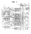
Fig. 1 is a schematic arrangement diagram showing one
embodiment of the electron beam apparatus in accordance with
the present invention;
Fig. 2 is a schematic arrangement diagram for further
detailed explanation of gap dehumidification means in Fig. 1;
Fig. 3 is a characteristics example for explanation of
the relation of an emission current and electron gun chamber
vacuum degree relative to acceleration voltage;
Fig. 4 is a schematic arrangement diagram showing another
embodiment of the gap dehumidification means in the present
invention;
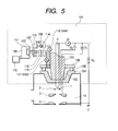
Fig. 5 is a schematic arrangement diagram showing a still
another embodiment of the gap dehumidification means in the
present invention; and
Fig. 6 is a flow diagram showing one embodiment procedure
of a self-diagnostics program in the present invention.
DESCRIPTION OF THE PREFERRED EMBODIMENTS
A preferred embodiment of the present invention will now
be explained in detail with reference to the accompanying
drawings below.
Fig. 1 is a schematic arrangement diagram showing one
embodiment of the electron beam apparatus in accordance with
the instant invention, which is an embodiment concerning a
scanning electron microscope (abbreviated as "SEM" hereinafter)
with a built-in electron gun of the Schottky emission type.
The Schottky emission type electron gun consists
essentially of aneedle-shaped or needle shaped cathode (SE-tip)
1, a suppressor electrode 2, a first anode 3, a second anode
4 and others. A extracting voltage V1 with its potential of
approximately 1 to 3 kV is applied between the needle shaped
cathode 1 and the first anode 3. This electric field is used
to cause electrons 5 to release out of the needle shaped cathode
which is configured from a ZrO/W tip. A flow of these electrons
will be detected as an emission current Ie. Part of these
electrons passes through a central hole of the first anode and
is then accelerated by an acceleration voltage Vo with a potential
of about 0.5kV to several tens of kV, which is applied between
the needle shaped cathode 1 and second anode 4.
Note here that the second anode 4 is set at the same potential
level as Earth (E) 6. Optionally, although not specifically
illustrated in the drawing, depending upon the electron gun used,
there is a case where a third anode (V2) is provided between
the first anode 3 and the second anode 4 for adjusting the focusing
function/operation of an electrostatic lens. The suppressor
electrode 2 is the electrode that is for suppressing unnecessary
thermal-electrons which are released by letting a heat-up
current If flow in a filament that supports the needle shaped
cathode 1. Applied thereto is a negative voltage Vs with a
potential of about 0.1 to 1kV. These If, Ie, Vs, V1 and Vo are
built in a high-voltage power supply 7 and connected to a
high-voltage control circuit 8 and a central control device (CPU)
9 which controls an entire system of SEM.
Electrons which are accelerated by the acceleration
voltage Vo pass through the center hole of the second anode 4
to become an electron beam 10. And an arrangement for adjusting
the focal point to be a desired position is made up of an
electromagnetic lens which is provided at lower part of the second
anode and is called a focusing lens (or alternatively condenser
lens) 11, a focusing lens power supply 12, and a focusing lens
control circuit 13. An electron gun chamber 14 is typically
maintained by an ion pump 15 at a vacuum degree (pressure) of
less than or equal to 10-7 Pa. In addition, an electromagnetic
lens chamber 16 in which the focusing lens 11 is put is retained
by another ion pump 17 at a vacuum degree (pressure) of less
than or equal to 10-6 Pa. It is noted that although the ion pump
of the electron gun chamber should not be limited to a single
one and may consist of a plurality of ones in some cases, an
explanation here is directed to an exemplary case where it
consists of a single one.
An electromagnetic lens, called an objective lens 18, is
further provided at the lower part of the focusing lens 11, wherein
an objective lens power supply 19 and an objective lens control
circuit 20 are used to focus the electron beam 10 on a sample
or specimen 22 which is mounted on a specimen stage 21. While
scanning this focused electron beam on a specimen surface by
use of a deflection coil 23 and a scanning power supply 24 plus
a magnification control circuit 25, let a signal detector 27
detect a signal such as secondary electrons 26 produced from
the specimen; then, amplify it by a signal amplifier 28.
Send this signal as an image signal to a cathode ray tube
(CRT) 29; then, observe it as a SEM image on the CRT.
Note that in case a need is felt to print out a scan image,
a camera device 30 is used to photograph a display image of a
photograph-use CRT 31; alternatively, let it be printed by an
image printer, not depicted herein. Still alternatively, use
a signal control circuit 32 and a memory circuit 33 to store
the image. Further, store it via the central control device
9 in an external storage device 37 such as a hard disk 34, optical
disc 35 or magneto-optical disc 36.
It should be noted that an air lock device 39 is provided
at lower part of the focusing lens 11 for vacuum-shielding a
passage between it and the sample chamber 38 and permitting
operative coupling thereto, which device is opened and closed
in specimen-exchange/replacement events.
The specimen chamber 38 is normally kept by a vacuum pump
40 such as a turbo molecular pump at a vacuum of the order of
magnitude of 10-4 Pa. The vacuum degree of each portion including
the specimen chamber 38 is controlled by a vacuum system control
circuit 41. Additionally an object movable diaphragm 42 is
provided above the objective lens 18 (or within an objective
lens gap) for shaping the electron beam to have a decreased
cross-section area and for cutting dispersed electrons. An
electron flow detector 43 is for detection of the amount of an
electron beam (probe current IP1) radiated onto this diaphragm
and a signal amplifier 44 operatively associated therewith are
further provided and coupled to a probe current IP1 detection
circuit 45.
On the other hand, the specimen 22 is provided with a
small-diameter deep hole which is equivalent to a Faraday cup,
wherein the center of this deep hole is adjusted by a specimen
stage drive power supply 46 and a stage control circuit 47 at
the center of an optical axis to thereby enable receipt of an
entire irradiation current onto the specimen. This is readily
done by maximally increasing the magnification while observing
the SEM image. Obviously, the specimen stage may be modified
so that it is manually movable. The specimen irradiation current
which was received at the hole on the specimen in this way is
detectable by a probe current IP2 detection circuit 49 as a probe
current IP2, by connecting it to a micro-current meter 48 outside
of the vacuum through a specimen current introduction terminal
(not shown) of the specimen stage 21. Optionally, this IP2
detection may also be performed by a Faraday cup (not shown)
which is separately attached to the specimen chamber.
The beam current which is taken out by the Schottky emission
type electron gun has a feature that it is extremely high in
brightness or luminance and stays at several % or less in
variation of beam current for an increased length of time period
to thereby offer enhanced stability. However, when discharge
occurs between electrodes of the electron gun and/or when
discharge takes place between electrical conductive portions
of the high-voltage cable and the high-voltage introduction
insulator and the Earth, the electron source' s tip end is rapidly
melt down, making it impossible to obtain any high-brightness
electron beam, which would sometimes result in inability to
obtain the required image resolution as SEM images. Regarding
electron beam apparatus and electron-gun good/bad judgment
method which are preferably used to perform evaluation of the
cause of any improper electron-beam radiation such as image
degradation and resolution reduction in this case, the present
inventors have been filed a patent application PCT/JP99/06258.
Note however that this is the one that concerns good/bad judgment
of the Schottky emission type electron source.
On the other hand, it will sometimes happen that the
dielectricity of surfaces of the high-voltage cable and
high-voltage introduction insulator decreases resulting in an
increase in leakage current upon application of a high voltage,
which in turn causes the beam current to become unstable thereby
causing the resolution to decrease accordingly. Although in
some cases these are caused by contamination of the high-voltage
cable and high-voltage introduction insulator surfaces and also
by attachment of dusts and contaminant particles thereto, it
is considered that the decrease in resolution is due to the fact
that water content on the high-voltage cable surface or the
high-voltage introduction insulator surface and in the gap
between the both is ionized causing micro discharge to readily
occur in cases where a temperature change of the electron gun
part is repeated many times by ON-OFF of the apparatus or
alternatively the creation of electron gun part discharge and/or
leakage current tends to readily occur under high humidity
environment. In view of the fact that once the electron source
is melt down due to discharging, long time is required to perform
a procedure covering from replacement of the electron source
up to successful start-up of the apparatus such as ultra-high
vacuum evacuation, electron gun baking, electron gun
conditioning (withstanding voltage test) and beam output and
the like, losses thereof are very large from view points of the
labor, time and cost. Due to this, this embodiment is equipped
with a means 101 for sealing and dehumidifying the electron gun
side of the high-voltage cable.
Fig. 2 is a schematic arrangement diagram for further
detailed explanation of the means 101 shown in Fig. 1, which
is for sealing the electron gun side of the high-voltage cable
and for dehumidifying a gap portion 102.
In Fig. 2, a high-voltage cable 103 is inserted into an
ambient air side high-voltage introduction insulator 104 of the
electron gun chamber and is connected to the needle shaped cathode
1 and the suppressor electrode 2 and the first anode 3, which
are within the electron gun chamber. An O-ring or a rubber
packing or a high dielectric seal material 106 made of polyimide
resin or else is provided between a holder 105 which is attached
to the outer peripheral part of this high-voltage cable 103 and
the high-voltage introduction insulator 104, thereby providing
a sealed space which prevents entry or invasion of any moisture
from the outside. In a normal beam output state, If, Vs, V1,
Vo turn ON, allowing a temperature of the needle shaped cathode
1 to stay at 1600K to 1800K. A contact surface of the high-voltage
cable and the high-voltage introduction insulator at this time
reaches 50°C to 60°C due to heat conduction from the filament
portion of the needle shaped cathode. Thus it is considered
that if water content is adsorbed at either the high-voltage
cable or the high-voltage introduction insulator, then it is
released to the gap portion 102 between the both and is then
ionized during high voltage application, which becomes the cause
of discharge and/or current leakage.
Although prior to insertion of the high-voltage cable into
the high-voltage introduction insulator a drier or the like is
customarily used to sufficiently dry the surfaces of the both
in advance, the state after insertion is not always completely
sealed with respect to the outside air and thus permits a little
amount of air to income and outgo through gaps of the sealing
member (O-ring or rubber packing or else) for sealing the outside
air and the conductive part of high-voltage cable and others.
In addition, as a heat cycle is applied due to a filament current
with ON-OFF of the high voltage power supply, it happens in some
cases that if water content from the outside air invades when
cooled, then ionization occurs while the acceleration voltage
is increasing in potential during re-startup of the high
voltage power supply, which in turn triggers creation of
discharge and/or current leakage. A sign of occurring this can
be predicted by the following method of the present invention.
To be brief, with this embodiment, in the state that the
high-voltage cable was inserted into the high-voltage
introduction insulator, set If, Vs, V1 to OFF (0V: note that
the terms "OFF" and "0V" are used in this specification to include
not only the case of strictly defined 0V but also the case of
a positive or negative voltage near 0V) while letting Vo alone
gradually rise up in potential; then, measure an emission current
Ie at that time. Its characteristics example is shown in Fig.
3.
In Fig. 3, if the surfaces of the high-voltage cable and
the high-voltage introduction insulator are made dry
sufficiently and if a gas at the gap portion 102 between the
both also is dried sufficiently then any appreciable change
hardly occurs in Ie up to a maximal acceleration voltage (e.g.
30kV) used generally even when the acceleration voltage
potentially increases as shown by "a" in the drawing. On the
contrary, in case water content is attached to the surfaces of
the high-voltage cable and high-voltage introduction insulator
or in case contaminants which give electrical conductivity are
attached thereto, a very small leakage current will become
detectable when the acceleration voltage reaches for example
about 25kV as shown by "b" in the drawing (an explanation as
to "c" and "d" in Fig. 3 will be given later). Continuously
monitor or watching this state for about 30 minutes; then, operate
a keyboard 50 shown in Fig. 1 to start a self-diagnostics program
51; next, output the Ie's change at every time point to a printer
53 through the high-voltage control circuit 8 and central control
device 9 or alternatively display it on the CRT 29. Additionally
let the storage device 37 store it. In case Ie exceeds a
prespecified value, for example when it goes beyond 0.5µA, give
a warning by use of a buzzer via an alarm display circuit 52
and the central processing unit (CPU) 9.
Alternatively, display the warning on the CRT 29 or display
the warning at the printer output device 53.
In the case of issuance of such warning, let Vo be OFF
(obviously, If, Vs and V1 also are also OFF'ed). Thereafter,
perform dehumidification by the gap dehumidifying means 101 shown
in Fig. 2. An example of this procedure will be described below.
In Fig. 2, open both a dry gas introduction valve (VA1) 107 and
a dry gas exhaust valve (VA2) 108 to thereby introduce a dry
gas from a dry gas device 109 for replacement of the presently
existing gas in the gap portion 102. After having done gas
replacement for a predefined length of time period, close said
valves VA1, VA2. Dry air or dry nitrogen gas is appropriate
for use as the dry gas. Note however that the dry nitrogen gas
requires significantly careful attention to the lack of oxygen.
Fig. 4 is the one that shows another embodiment of part
relating to the dry gas device 109 shown in Fig. 2. A gas exhaust
means (air compressor) 110 for chase-off of the gas at the gap
portion 102 is attached to the dry gas send-out side to thereby
facilitate replacement with a dry gas while providing a drying
agent or desiccant 111 for enhancing the dehumidification degree
of the dry gas (typically, air) along with an air filter 112
for removal of ultrafine or micro ducts in the air. Whereby,
it becomes possible to perform rapid replacement of a clean dry
gas with increased purity.
Fig. 5 is the one that shows still another embodiment of
the part relating to the dry gas device 109 shown in Fig. 2 while
adding the following functions to the embodiment of Fig. 4.
More specifically, a means (mechanical vacuum pump such
as an oil rotary pump or mechanical booster, or alternatively,
sorption pump or else) 113 for exhausting the gas of the gap
portion 102 is provided on the dry gas send-out side. Note here
that in the case of an oil rotary pump, it is desired that a
foreline trap be provided between it and the dry gas exhaust
valve (VA2) 108 although not specifically depicted in the
drawing to thereby prevent an oil vapor or steam from the oil
rotary pump from backflowing toward the gap portion 102 side.
Additionally in the embodiment of Fig. 5, a humidity sensor 114,
a temperature sensor 115 and a pressure sensor 116 are provided
at part of the flow path of such dry gas. With such an arrangement,
it becomes possible to monitor the humidity, temperature and
pressure of the gap portion and the flow path of the dry gas
at any time. The humidity sensor 114 is more effective if the
data history of the humidity of a flow path system is recorded.
The temperature sensor 115 is useful for temperature management
in the case of letting a dry gas higher than room temperatures
flow in the flow path system to thereby achieve efficient
dehumidification. Additionally the pressure sensor 116 is
useful for adjustment of the pressure of the flow path system
to thereby prevent it from getting higher or lower than required
and also for surveillance as to the safety.
It should be noted that since there is a risk that water
content is also possibly released out of said desiccant 111,
air filter 112 and humidity sensor 114 and others, an open/close
valve (VA3) 117 and an open/close valve (VA4) 118 may be provided
at locations maximally adjacent to the gap portion 102 on the
high-voltage introduction insulator side as shown in Fig. 5,
wherein the former is on the entrance side of the dry gas flow
path whereas the latter is on the exit side thereof.
Incidentally, after having done replacement of the gas
of the gap portion 102 between the high-voltage cable and
high-voltage introduction insulator in this way, again apply
Vo up to its maximum value―if the resultant value of Ie falls
within a predetermined value, then it is found that it is due
to the humidity of this gap portion, which makes it possible
to perform a stable beam output operation for a long time.
Alternatively, if Ie is absent within the predetermined
value then the cause does not lie in the water content on the
ambient air side of the electron gun and thus another cause must
be present. In such a case, it can be considered that a leakage
current is produced by electric field emission due to micro
projections generated between constituent members within the
electron gun―for example, between the first anode 3 and the
second anode 4 and/or between an electrode other than the needle
shaped cathode 1 and the Earth potential member―and/or surface
contamination of in-the-vacuum members such as dielectric
insulators, resulting in detection of a little amount of Ie.
In this case, although the probe currents IP1 and IP2 below the
electron gun are not detected, a release gas due to Ie is present,
which will appear as a change of the electron-gun chamber vacuum
degree (PG) as shown in d on Fig. 3 in the ion pump 15 which
is the ultrahigh vacuum exhaust means of the electron gun chamber
14―that is, a change in ion current of the ion pump. Monitoring
this enables verification of current leakage phenomena within
the electron gun chamber. In place of the ion pump current,
a vacuum degree change may be detected by attaching a vacuum
meter to part of the electron gun chamber. If the Ie change
and the vacuum degree change are in one-to-one correspondence,
then this is the problem within the electron gun chamber; thus,
self-diagnosis becomes possible, suggesting that
parts-maintenance inspection and cleaning of the constituent
members within the electron gun are necessary. Alternatively
in case no changes are found in vacuum degree of the electron
gun chamber (example of c in Fig. 3), it is considered that
contamination on the surface of either the high-voltage cable
or the high-voltage introduction insulator outside of the
electron gun chamber must cause the leakage current; if this
is the case, it is possible to judge that cleaning of these surfaces
is required, which makes it possible to make a proper decision
of maintenance works to be done.
The procedure as has been shown in the above embodiment
is built in said self-diagnostics program 51, wherein this
self-diagnostics program get started appropriately within a
fixed length of time period to thereby sequentially execute
detection of a change in emission current due to acceleration
voltage application and detection of a change in emission current
due to dry gas replacement and then issue a warning in case
abnormality is found in the emission current during the process,
thereby making it possible to provide the electron beam apparatus
with enhanced maintenance capability and increased usability.
Fig. 6 is an implementable procedure example of the
self-diagnostics program of the present invention. In Fig. 6,
assume that the apparatus conditions at step S11 are such that
the vacuum degree of the electron gun is normal with the state
of high-voltage power supply units being set, for example, at
any one of the following settings:
At step S12, the keyboard 50 shown in Fig. 1 is used to
allow the self-diagnostics program 51 to get started.
Preferably this is built in one of menus of a maintenance screen
(not shown) of the apparatus. At step S13, all of If, Ie, Vs,
V1, Vo become OFF temporarily.
At step S14, gradually increase Vo up to its maximum value
(e.g. 30 to 35kV); then, detect Ie and PG; next, store them in
the central control device 9. At step S15, the relation of these
detected Ie and Vo―for example, a characteristics example such
as b of Fig. 3―is displayed on the screen of CRT 29. This may
alternatively be arranged so that it is displayed on a real time
basis at every time point. Obviously PG (electron-gun chamber
vacuum degree) may also be displayed thereon simultaneously.
In addition, the values of Vo and Ie, e.g. Vo=30kV, Ie=0.55µA,
are displayed. At step S16, diagnosis is done to determine
whether the above value is within a prespecified value or exceeds
the prespecified value. This may be automated or alternatively
manually executed based on an operator's judgment. If within
the prespecified value, then determine the electron gun is free
from the abnormality; thereafter, proceed to a normal operation
such as SEM image observation. If in excess of the prespecified
value then determine it is abnormal: in this case, a warning
message, for example, "Leakage current is found. Check Electron
Gun" is displayed on the screen (not shown); then, go to step
S18. At step S18, diagnosis is done to determine the vacuum
degree PG of the electron gun chamber is within a predetermined
value. If it exceeds this value, then proceed to step S19 which
displays on the screen a warning message of "Abnormality is found
in Electron Gun. " If within the value, then go to step S20 which
displays on the screen a warning message of "Abnormality is found
outside Electron Gun" and then go next to step S21. At step
S21, prompt judgment as to "whether the dry gas flow means is
installed." This may be judged by the apparatus per se or
alternatively judged by the operator. If not installed, then
a warning message of "Check High-Voltage Insulator and
High-Voltage Cable, then Dry" is displayed on the screen at step
S22. If installed, then let a dry gas flow after turn-off of
the high-voltage power supply at step S23. This may be automated
or alternatively manually done by the operator. After having
flown the dry gas, dried the surfaces of the high-voltage cable
and high-voltage introduction insulator, and replaced a gas at
the gap portion between the both with the dry gas, return to
step S12 which forces the self-diagnostics program to restart.
Thereafter, through similar processes, diagnosis is performed
to verify whether the electron gun is in the normal state.
It must be noted that although in this embodiment the
explanation was given as to the electron beam apparatus having
the Schottky emission type electron gun, it is obvious that the
content of the present invention should not be limited only to
this and that similar effects are obtainable even when applied
to electron gun apparatus having a cathode electric field
emission type electron gun or thermal electric field emission
type electron gun.
As has been explained above, in accordance with the present
invention, it is possible to provide an electron beam apparatus
and method which can retain the state that minimizes the amount
of water content contained at the gap between a high-voltage
cable and a high-voltage introduction insulator to thereby
enable preclusion of creation of any high-voltage discharge
and/or current leakage. In addition, it is possible to provide
an electron beam apparatus which can rapidly and accurately
perform maintenance tasks in electron beam irradiation abnormal
events and thus offer enhanced usability.