EP1336916A2 - Position-direction measuring apparatus and information processing method - Google Patents
Position-direction measuring apparatus and information processing method Download PDFInfo
- Publication number
- EP1336916A2 EP1336916A2 EP03250987A EP03250987A EP1336916A2 EP 1336916 A2 EP1336916 A2 EP 1336916A2 EP 03250987 A EP03250987 A EP 03250987A EP 03250987 A EP03250987 A EP 03250987A EP 1336916 A2 EP1336916 A2 EP 1336916A2
- Authority
- EP
- European Patent Office
- Prior art keywords
- sensor
- value
- hemisphere
- point symmetrical
- point
- Prior art date
- Legal status (The legal status is an assumption and is not a legal conclusion. Google has not performed a legal analysis and makes no representation as to the accuracy of the status listed.)
- Granted
Links
Images






Classifications
-
- G—PHYSICS
- G06—COMPUTING OR CALCULATING; COUNTING
- G06F—ELECTRIC DIGITAL DATA PROCESSING
- G06F3/00—Input arrangements for transferring data to be processed into a form capable of being handled by the computer; Output arrangements for transferring data from processing unit to output unit, e.g. interface arrangements
- G06F3/01—Input arrangements or combined input and output arrangements for interaction between user and computer
- G06F3/011—Arrangements for interaction with the human body, e.g. for user immersion in virtual reality
Definitions
- the present invention relates to a technology of judging a sensor position utilizing a position-direction measuring apparatus which executes measurement by setting a hemisphere (semi-sphere) with a transmitter positioned at the center thereof and utilizing an assumption that a sensor is present within such hemisphere.
- CG computer graphics
- Such sensor of magnetic type is composed of a transmitter generating a magnetic field, a sensor to be attached to an object of which position and direction are to be measured, and a controlling main body, but, in the position measurement, is in principle incapable of recognizing where the sensor is actually present among two points which is point-symmetrical with respect to the position of the transmitter.
- the measurement is generally executed by setting a hemisphere around the transmitter and assuming that the sensor is present within such hemisphere.
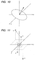
- a plane as shown in Fig. 10 is taken as a boundary, and the measurement is executed only in a side indicated by an arrow.
- the transmitter is assumed to be present at the original point. Therefore the measurable area is inevitably halved.
- a manual for the Flock of Birds of Ascension Corp. describes a method of determining the hemisphere in which the sensor is present by tracking the sensor from the past measured values, thereby achieving measurement in the entire sphere.
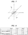
- Fig. 9 shows a flow of such process, and such process will be explained with an example of measurement shown in Figs. 7 and 8.
- the measurement is initiated by placing the sensor in a position where the Y-value is positive. In this state, the output value from the measuring device coincides with the true value (in hemisphere) (step S2201).
- step S2203 there is discriminated whether signals other than the Y-signal which is assumed to remain positive, namely X-signal and Z-signal, have simultaneously changed signs thereof, and, a shift to another hemisphere is judged to have taken place in case of simultaneous changes of the signs (step S2203).
- step S2204 there is memorized information indicating a new hemisphere. It is thus possible to memorize the hemisphere judged in the step S2203 (step S2204).
- the hemisphere determined in the step S2203 is the hemisphere assumed by the measuring device (initial hemisphere) (step S2205), and, if it is different from the initial hemisphere, the measured values are converted to point-symmetrical values by respectively inverting the X-, Y- and Z-values (step S2206), and stored as a current position (step S2207).
- the X-, Y- and Z-values are stored as a current position.
- the measuring device outputs values of a position B'.
- the X-value and the Z-value are simultaneously inverted, so that there can be judged a shift to another hemisphere, namely from A to B, and the position B can be judged as the correct measured value.
- the senor may be so moved as to simultaneously change the signs on two axes of which sign is not assumed as positive nor negative.
- the measurement start position of the sensor for determining the initial hemisphere cannot be set in a hemisphere which is inclined to the coordinate system as shown in Fig. 10 but there has to be selected a hemisphere of which each of X-, Y-and Z-values is fixed as positive or negative (namely a hemisphere at above, at below, at right, at left, in front or at rear), so that the installation or operation of the transmitter is limited.
- An object of the present invention is to reduce the possibility of causing an error and to enable arbitrary setting of the hemisphere at the start of measurement for determining the initial hemisphere.
- the present invention has a following configuration.
- a position-direction measuring apparatus that is in principle incapable of determining a true position among two positions which are point symmetrical with respect to a certain point
- the apparatus including a unit for setting an initial position among two points, a unit for setting a reference position based on a past measurement result, a unit for determining positions of point symmetrical two points from a measurement value, a unit for determining respective distances from the reference position to the point symmetrical two points, and a unit for selecting a position, among the position of the point symmetrical two points, corresponding to a shorter one of thus determined distances, as a current measurement result.
- an information processing method for judging a sensor position utilizing a position direction measuring apparatus for setting a hemisphere having a transmitter at the center thereof and executing a measurement based on an assumption that the sensor is present within the hemisphere including steps of acquiring a measured value from the sensor, determining a point symmetrical value indicating a position which is point symmetrical to the above-mentioned measured value with respect to the transmitter, determining distances from a reference value corresponding to a past sensor position to the above-mentioned measured value and to the above-mentioned point symmetrical value respectively, and selecting the above-mentioned measured value or the above-mentioned point symmetrical value corresponding to a shorter one of thus determined distances, as a current sensor position.
- Fig. 1 is a view schematically showing the configuration of a composite reality system embodying first embodiment.
- a first observer 100 wears an HMD (head mount display on the head and a glove 120 on a hand.
- HMD head mount display on the head and a glove 120 on a hand.
- the HMD 110 is composed, as shown in Fig. 2, of a video camera 111, an LCD 112, a receiver (eye position sensor) 113 for the position-direction measuring apparatus, optical prisms 114, 115.
- the video camera 111 captures a real space image at a view position and in a view direction of the observer, guided by the optical prism 115.
- the eye position sensor 113 is utilized for measuring the view position and the view direction of the observer.
- the LCD 113 display a composite real space image, which is guided by the optical prism 114 to the eye of the observer.
- the glove 120 incorporates a hand position sensor 121, and a loud speaker (not shown).
- the hand position sensor 121 is used as a sensor for measuring the position and direction of the hand of the observer.
- the speaker generates a sound corresponding to an event generated in a hand position.
- the sound can be, for example, a sound generated when an object in the virtual space is touched or slapped by the hand, or a sound generated when an object in the virtual space, displayed in synchronization of the hand position, changes a state.
- a transmitter (position sensor transmitter) 130 of the position direction measuring apparatus and a main body 131 (position sensor main body) of the position direction measuring apparatus.
- the eye position sensor 113, the hand position sensor 121 and the position sensor transmitter 130 are connected to the position sensor main body 131.
- the position sensor transmitter 130 emits a magnetic flux, which is received by the dye position sensor 113 and the hand position sensor 121.
- the position sensor main body 131 Based on reception intensity signals from the eye position sensor 113 and the hand position sensor 121, the position sensor main body 131 calculates the position and the direction of the eye and the hand.
- the position direction measuring apparatus there can be utilized, for example, the FASTRAK manufactured by Polhemus Corp., U.S.
- a processing apparatus 140 generates a composite reality space image for an observer and displays it in the HMD 110.
- the processing apparatus 140 may be composed, for example, of a personal computer, a video capture card, a video card having a CG drawing function, a sound card etc.
- the processing apparatus 140 is connected to the HMD 110, the speaker, and the position sensor main body 131.
- a numeral 170 indicates a virtual character which is so composed as if riding on the hand of the first observer 100.
- a numeral 180 indicates a view line of the first observer. The view line can be measured by the eye position sensor 113, the position sensor transmitter 130 and the position sensor main body 131.
- a second observer 101 is constructed in a similar manner as the first observer.
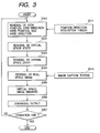
- the processing apparatus 140 fetches a view position, a view direction, a hand position and a hand direction, transmitted from the position sensor main body 131 (step S301).
- the step S301 utilizes a thread S311, for periodically fetching the view position, the view direction, the hand position and the hand direction transmitted from the position sensor main body 131.
- step S302 the time of the virtual space is renewed, and the state of the virtual space (kind, position and state of the virtual space object) is renewed (step S302).
- the state such another virtual space object is also renewed. For example, in case of displaying a virtual character as if riding always on a hand, this step S302 also renews the position and the direction of the glove.
- step S303 a relationship between the position and the direction of the virtual space object (hand position and view position), and the position and the direction of the virtual space object is investigated, and, in case an event defined in advance is judged to have occurred, the state of the virtual space is renewed according to such event (step S303).
- the virtual space object may be caused to explode when it is touched by the hand.
- step S304 there is fetched a real space image, obtained by the video camera 111 at the view position and the view direction of the observer (step S304).
- This step S304 utilizes a thread S314 for periodically acquires the real space image, obtained from the video camera 111, from the video capture card.
- step S305 a virtual space image is generated in the view position and the view direction of the observer obtained in the step S301, according to the state of the virtual space renewed in the steps S302, S303 (step S305).
- step S305 the virtual space image generated in the step S305 and the real space image fetched in the step S304 are synthesized and outputted to the LCD 112 of the HMD 110 (step S306).
- Figs. 4 and 5 are external views of the HMD 110, respectively seen from a direction of an image pickup unit and a direction of a display unit.
- An HMD display unit 201 includes a right eye display 201R and a left eye display 201L, each having a color liquid crystal display and a prism, and displaying a composite real space image corresponding to the view position and the view direction of the observer.
- Members 204 to 208 constitute a head mounting portion.
- a head mounting portion For mounting the HMD 301 on the head, it is placed on the head in a state where a length adjusting portion 206 is loosened by an adjuster 205. Then, after a forehead mounting portion 208 is brought into contact with the forehead, the length adjusting portion 206 is tightened with the adjuster 205 so as that a lateral head mounting portion 204 and a rear head mounting portion 207 are respectively in contact with a lateral portion and a rear portion of the head.
- An HMD image pickup unit 203 for taking the real space image in the view position and the view direction of the observer, includes a right eye image pickup unit 203R and a left eye image pickup unit 203L, each composed of a small video camera of NTSC system.
- the taken real space image is superposed with the virtual space image to form a composite real space image.
- a receiver 302 is used for receiving the magnetic flux emitted from the transmitter, as information for measuring the view position and the view direction of the observer.
- the receiver 302 For connecting the receiver 302 on the HMD 110, there are provided three receiver connecting portions 200R, 200L, 200C, and the receiver 302 can be detachably mounted on any of these receiver connecting portions.
- the receiver 302 is connecting on the receiver connecting portion 200R at the right side of the view direction of the observer, but it may also be connected on the receiver connecting portion 200L at the left side of the view direction of the observer, or on the receiver connecting portion 200C on the central line of the observer.
- the receiver connecting portions 200R, 200L, 200C are so constructed as to have a slot in which the receiver 302 is fitted and fixed, but there may also be adopted any other detachable mounting method.
- a receiver signal line 210 is positioned in the vicinity of the receiver connecting portion 200C and is exposed to the exterior of the HMD 301.
- the receiver signal line 210 has such a sufficient length that the receiver 302 can be connected to any of the receiving connecting portions 200R, 200L, and 200C.
- a wire harness 209 collectively includes various lines such as signal lines to the HMD display unit 201 and the HMD image pickup unit, a power supply line and the aforementioned receiver signal line 210, and is mounted on the rear head mounting portion 207.
- the signal lines to the left and right display units 201R, 201L and the left and image pickup units 203R, 203L, and the power supply lines thereto pass through the respective side head mounting portions 204 at the left and at the right.
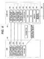
- Fig. 6 is a block diagram showing the hardware configuration for an observer in the system shown in Fig. 1.
- a processing apparatus (computer) 307 there are provided a right eye video capture board 350, a left eye video capture board 351, a right eye graphic board 352, a left eye graphic board 353, an I/O interface 354 and a network interface 359, and these components are connected with a CPU 356, an HDD 355 and a memory 357.
- the video capture boards 351, 350 for the left and right eyes are respectively connected to the video cameras 203L, 203R for the left and right eyes, and convert real images, fetched by the video cameras 203L, 203R, into formats that can be composed with the virtual space images in the main processing apparatus 307.
- the graphic boards 353, 352 for the left and right eyes are respectively connected to the display units (apparatus) 201L, 201R for the left and right eyes and execute display control for such display units 201L, 201R for the left and right eyes.
- the I/O interface 354 is connected to the main body 306 of the position direction measuring apparatus, and the network interface 359 is connected to a network 330.
- sensors 130, 131, 113, 121 are ordinary magnetic sensors and do not have a function of tracking the hemisphere.
- the sensor 113 is positioned within a predetermined initial hemisphere for starting the measurement, and the measurement is started (step S3301). In this state a measured value is received from the main body 131 of the measuring device and memorized. Then the computer 140 receives the measured value from the main body 131 of the measuring device (step S3302).
- step S3303 a position which is point symmetrical to the received measured position, with respect to the transmitter.
- the value of the point symmetrical position can be obtained by inverting the signs of the measured X, Y and Z values.
- step S3304 there is calculated a distance between the previous measured value and the position measured in the step S3302 (step S3304). There is also calculated a distance between the previous measured value and the point symmetrical position determined in the step S3304 (step S3305).
- step S3306 Based on the results of the steps S3304 and S3305, a shorter distance is judged as the true value, and a position corresponding to thus judged true value is determined as the sensor position (step S3306).
- the measured value judged as the true value in the step S3306 is transferred to S311 in Fig. 3, and is stored for a next measurement process (step S3307).
- the measurement is started with the sensor at first in a position C.
- the prior method results in an erroneous judgment that the sensor has moved to D' because the X and Z values are both inverted as will be apparent from the comparison of the measured values of C and D in Fig. 12.
- the present embodiment calculates the distances C-D and C-D' and can decide that D is the real position based on a fact that the distance C-D is shorter.
- the present embodiment allows, in a position direction measuring apparatus of magnetic type or a similar method that is incapable of identifying the true value among point-symmetrical two points, to estimate with a lower possibility of error the true value among two hemispheres, and also to arbitrarily set the hemisphere at the start of the measurement.
- the previous measured position is employed as a reference value in judging the true value of the sensor position.
- the present invention includes a case where the program codes of a software realizing the functions of the aforementioned embodiments are supplied to a computer of a system or an apparatus connected to various devices in order to operate the devices so as to realize the functions shown in Fig. 14 and the functions of the aforementioned embodiments are realized by operating the devices by the computer (CPU or MPU) of the above-mentioned system or apparatus according to the program codes.
- program codes themselves of the software realize the functions of the aforementioned embodiments, and the program codes themselves and the means for supplying the computer with such program codes, for example a memory medium storing the program codes, constitutes the present invention.
- the memory medium for supplying such program codes can be, for example, a floppy disk, a hard disk, an optical disk, a magnetooptical disk, a CD-ROM, a magnetic tape, a non-volatile memory card or a ROM.
- the present invention also includes such program codes not only a case where the functions of the aforementioned embodiments are realized by the execution of the supplied program codes by the computer but also a case where an operating system or the like functioning on the computer executes all or a part of the actual processes under the control of such program codes thereby realizing the functions of the aforementioned embodiments.
- the present invention further includes a case wherein the supplied program codes are once stored in a memory provided in a function expansion board inserted into the computer or a function expansion unit connected to the computer, and a CPU provided in the function expansion board or the function expansion unit executes all the process or a part thereof according to the instructions of such program codes, thereby realizing the functions of the aforementioned embodiments.
Landscapes
- Engineering & Computer Science (AREA)
- General Engineering & Computer Science (AREA)
- Theoretical Computer Science (AREA)
- Human Computer Interaction (AREA)
- Physics & Mathematics (AREA)
- General Physics & Mathematics (AREA)
- Length Measuring Devices With Unspecified Measuring Means (AREA)
- Measurement Of Length, Angles, Or The Like Using Electric Or Magnetic Means (AREA)
- Position Input By Displaying (AREA)
- Length Measuring Devices By Optical Means (AREA)
Abstract
Description
Claims (7)
- A position-direction measuring apparatus that is in principle incapable of determining a true position among two positions which are point symmetrical with respect to a certain point, the apparatus comprising:a unit for setting an initial position among two points;a unit for setting a reference position based on a past measurement result;a unit for determining positions of point symmetrical two points from a measurement value;a unit for determining respective distances from the reference position to the point symmetrical two points; anda unit for selecting a position, among the positions of the point symmetrical two points, corresponding to a shorter one of thus determined distances, as a current measurement result.
- An apparatus according to claim 1, wherein said setting unit sets a preceding measurement result as said reference position.
- An apparatus according to claim 1, wherein said setting unit sets an average of two or more measurement results in the past as said reference position.
- An apparatus according to claim 1, wherein said setting unit sets a weighted average of two or more measurement results in the past as said reference position.
- An information processing method for judging a sensor position utilizing a position direction measuring apparatus for setting a hemisphere having a transmitter at the center thereof and executing a measurement based on an assumption that the sensor is present within the hemisphere, the method comprising steps of:acquiring a measured value from the sensor;determining a point-symmetrical value representing a position which is point symmetrical to the measured value with respect to the transmitter, and determining distances from a reference value corresponding to a past sensor position to the measured value and to the point symmetrical value respectively; andselecting the measured value or the point symmetrical value corresponding to a shorter one of thus determined distances, as a current sensor position.
- A computer program for an information processing method for judging a sensor position utilizing a position direction measuring apparatus for setting a hemisphere having a transmitter at the center thereof and executing a measurement based on an assumption that the sensor is present within the hemisphere, the method comprising steps of:acquiring a measured value from the sensor;determining a point-symmetrical value representing a position which is point symmetrical to the measured value with respect to the transmitter, and determining distances from a reference value corresponding to a past sensor position to the measured value and to the point symmetrical value respectively; andselecting the measured value or the point symmetrical value corresponding to a shorter one of thus determined distances, as a current sensor position.
- A computer readable memory medium storing a computer program for an information processing method for judging a sensor position utilizing a position direction measuring apparatus for setting a hemisphere having a transmitter at the center thereof and executing a measurement based on an assumption that the sensor is present within the hemisphere, the method comprising steps of:acquiring a measured value from the sensor;determining a point-symmetrical value representing a position which is point symmetrical to the measured value with respect to the transmitter, and determining distances from a reference value corresponding to a past sensor position to the measured value and to the point symmetrical value respectively; andselecting the measured value or the point symmetrical value corresponding to a shorter one of thus determined distances, as a current sensor position.
Applications Claiming Priority (2)
| Application Number | Priority Date | Filing Date | Title |
|---|---|---|---|
| JP2002040091 | 2002-02-18 | ||
| JP2002040091A JP3762309B2 (en) | 2002-02-18 | 2002-02-18 | POSITION / DIRECTION MEASURING DEVICE AND INFORMATION PROCESSING METHOD |
Publications (3)
| Publication Number | Publication Date |
|---|---|
| EP1336916A2 true EP1336916A2 (en) | 2003-08-20 |
| EP1336916A3 EP1336916A3 (en) | 2004-03-17 |
| EP1336916B1 EP1336916B1 (en) | 2007-08-01 |
Family
ID=27621475
Family Applications (1)
| Application Number | Title | Priority Date | Filing Date |
|---|---|---|---|
| EP03250987A Expired - Lifetime EP1336916B1 (en) | 2002-02-18 | 2003-02-18 | Position-direction measuring apparatus and information processing method |
Country Status (4)
| Country | Link |
|---|---|
| US (1) | US6892162B2 (en) |
| EP (1) | EP1336916B1 (en) |
| JP (1) | JP3762309B2 (en) |
| DE (1) | DE60315207T2 (en) |
Cited By (2)
| Publication number | Priority date | Publication date | Assignee | Title |
|---|---|---|---|---|
| EP1538512A3 (en) * | 2003-12-04 | 2007-01-17 | Canon Kabushiki Kaisha | Mixed reality exhibiting method and apparatus |
| US10134192B2 (en) | 2016-10-17 | 2018-11-20 | Microsoft Technology Licensing, Llc | Generating and displaying a computer generated image on a future pose of a real world object |
Families Citing this family (12)
| Publication number | Priority date | Publication date | Assignee | Title |
|---|---|---|---|---|
| JP5794686B2 (en) | 2011-08-10 | 2015-10-14 | キヤノン株式会社 | Imaging apparatus and driving method thereof |
| US9671566B2 (en) | 2012-06-11 | 2017-06-06 | Magic Leap, Inc. | Planar waveguide apparatus with diffraction element(s) and system employing same |
| KR20230044041A (en) | 2013-03-11 | 2023-03-31 | 매직 립, 인코포레이티드 | System and method for augmented and virtual reality |
| CN105229719B (en) | 2013-03-15 | 2018-04-27 | 奇跃公司 | Display system and method |
| US10146299B2 (en) * | 2013-11-08 | 2018-12-04 | Qualcomm Technologies, Inc. | Face tracking for additional modalities in spatial interaction |
| US10078218B2 (en) | 2016-01-01 | 2018-09-18 | Oculus Vr, Llc | Non-overlapped stereo imaging for virtual reality headset tracking |
| US20180074607A1 (en) * | 2016-09-11 | 2018-03-15 | Ace Zhang | Portable virtual-reality interactive system |
| KR102698364B1 (en) | 2017-10-26 | 2024-08-23 | 매직 립, 인코포레이티드 | Wideband adaptive lens assembly for augmented reality displays |
| CN116300091A (en) * | 2018-07-23 | 2023-06-23 | 奇跃公司 | Method and system for resolving hemispherical ambiguity using position vectors |
| JP2021536592A (en) | 2018-08-31 | 2021-12-27 | マジック リープ, インコーポレイテッドMagic Leap, Inc. | Spatically decomposed dynamic dimming for augmented reality devices |
| JP7585206B2 (en) | 2019-01-11 | 2024-11-18 | マジック リープ, インコーポレイテッド | Time-multiplexed display of virtual content at different depths |
| CN113383294B (en) | 2019-01-28 | 2024-12-17 | 奇跃公司 | Method and system for resolving hemispherical ambiguity in six-degree-of-freedom pose measurements |
Family Cites Families (11)
| Publication number | Priority date | Publication date | Assignee | Title |
|---|---|---|---|---|
| JPH0778540B2 (en) * | 1990-09-27 | 1995-08-23 | 防衛庁技術研究本部長 | Magnetic detection device capable of position localization |
| US5307072A (en) * | 1992-07-09 | 1994-04-26 | Polhemus Incorporated | Non-concentricity compensation in position and orientation measurement systems |
| JP2500347B2 (en) * | 1992-08-21 | 1996-05-29 | 防衛庁技術研究本部長 | Positioning device for moving objects using three 1-axis magnetometers |
| US5600330A (en) * | 1994-07-12 | 1997-02-04 | Ascension Technology Corporation | Device for measuring position and orientation using non-dipole magnet IC fields |
| JP3095973B2 (en) * | 1995-03-24 | 2000-10-10 | ケイディディ株式会社 | Earth station position detection method in satellite communication system |
| JP3749369B2 (en) * | 1997-03-21 | 2006-02-22 | 株式会社竹中工務店 | Hand pointing device |
| FR2768528B1 (en) * | 1997-09-18 | 2001-01-12 | Aerospatiale | COMPUTER INPUT DEVICE, AUTOMATICALLY SWITCHED BETWEEN 3D AND 2D OPERATING MODES, AND ITS INTERACTION METHOD WITH A DISPLAY SCREEN |
| JP4452868B2 (en) * | 1998-11-12 | 2010-04-21 | 独立行政法人産業技術総合研究所 | Measurement method in magnetic motion capture device |
| US6611242B1 (en) * | 1999-02-12 | 2003-08-26 | Sanyo Electric Co., Ltd. | Information transmission system to transmit work instruction information |
| JP3397772B2 (en) * | 2001-03-13 | 2003-04-21 | キヤノン株式会社 | Sensor mounting device, sensor or marker mounting device |
| JP2002296349A (en) * | 2001-04-03 | 2002-10-09 | Fujitsu Ltd | Ultrasonic positioning system |
-
2002
- 2002-02-18 JP JP2002040091A patent/JP3762309B2/en not_active Expired - Fee Related
-
2003
- 2003-02-14 US US10/366,339 patent/US6892162B2/en not_active Expired - Fee Related
- 2003-02-18 EP EP03250987A patent/EP1336916B1/en not_active Expired - Lifetime
- 2003-02-18 DE DE60315207T patent/DE60315207T2/en not_active Expired - Lifetime
Cited By (3)
| Publication number | Priority date | Publication date | Assignee | Title |
|---|---|---|---|---|
| EP1538512A3 (en) * | 2003-12-04 | 2007-01-17 | Canon Kabushiki Kaisha | Mixed reality exhibiting method and apparatus |
| US7330197B2 (en) | 2003-12-04 | 2008-02-12 | Canon Kabushiki Kaisha | Mixed reality exhibiting method and apparatus |
| US10134192B2 (en) | 2016-10-17 | 2018-11-20 | Microsoft Technology Licensing, Llc | Generating and displaying a computer generated image on a future pose of a real world object |
Also Published As
| Publication number | Publication date |
|---|---|
| US6892162B2 (en) | 2005-05-10 |
| JP2003240532A (en) | 2003-08-27 |
| EP1336916A3 (en) | 2004-03-17 |
| US20030158654A1 (en) | 2003-08-21 |
| JP3762309B2 (en) | 2006-04-05 |
| DE60315207D1 (en) | 2007-09-13 |
| DE60315207T2 (en) | 2008-04-17 |
| EP1336916B1 (en) | 2007-08-01 |
Similar Documents
| Publication | Publication Date | Title |
|---|---|---|
| CN110647237B (en) | Gesture-based content sharing in an artificial reality environment | |
| US9288468B2 (en) | Viewing windows for video streams | |
| US7610558B2 (en) | Information processing apparatus and method | |
| EP1336916A2 (en) | Position-direction measuring apparatus and information processing method | |
| US9110503B2 (en) | Precision position tracking device | |
| CN108535868B (en) | Head-mounted display device and control method thereof | |
| EP2040145B1 (en) | Image processing method and input interface apparatus | |
| US20160131902A1 (en) | System for automatic eye tracking calibration of head mounted display device | |
| CN113544766B (en) | Registering local content between first and second augmented reality viewers | |
| CN102591016A (en) | Optimized focal area for augmented reality displays | |
| CN106291930A (en) | Head-Mounted Display | |
| CN110895676A (en) | Dynamic object tracking | |
| JPH10198506A (en) | System for detecting coordinate | |
| JP2021056371A (en) | Display system, display method, and display program | |
| CN120077343A (en) | Method and electronic device for providing AR information using image | |
| US12111463B2 (en) | Head-mounted display apparatus and operating method thereof | |
| US20250200907A1 (en) | Information processing apparatus capable of positively grasping sound in real space, method of controlling information processing apparatus, and storage medium | |
| US20260080509A1 (en) | Systems, apparatuses, and methods for active alignment for video passthrough of modular sensors and head-mounted displays | |
| US20250148727A1 (en) | Information processing apparatus controlling reproduction of video of virtual object, control method of information processing apparatus, and storage medium | |
| US11994675B2 (en) | Head-mounted device for tracking screen time | |
| US20250355284A1 (en) | Eyewear with direction of sound arrival detection | |
| EP4206867A1 (en) | Peripheral tracking system and method | |
| CN218848735U (en) | Image display device, intelligent panel, notebook computer and display | |
| EP4633136A1 (en) | Electronic device and method for providing virtual space image |
Legal Events
| Date | Code | Title | Description |
|---|---|---|---|
| PUAI | Public reference made under article 153(3) epc to a published international application that has entered the european phase |
Free format text: ORIGINAL CODE: 0009012 |
|
| AK | Designated contracting states |
Designated state(s): AT BE BG CH CY CZ DE DK EE ES FI FR GB GR HU IE IT LI LU MC NL PT SE SI SK TR |
|
| AX | Request for extension of the european patent |
Extension state: AL LT LV MK RO |
|
| PUAL | Search report despatched |
Free format text: ORIGINAL CODE: 0009013 |
|
| AK | Designated contracting states |
Kind code of ref document: A3 Designated state(s): AT BE BG CH CY CZ DE DK EE ES FI FR GB GR HU IE IT LI LU MC NL PT SE SI SK TR |
|
| AX | Request for extension of the european patent |
Extension state: AL LT LV MK RO |
|
| 17P | Request for examination filed |
Effective date: 20040729 |
|
| 17Q | First examination report despatched |
Effective date: 20040827 |
|
| AKX | Designation fees paid |
Designated state(s): DE FR GB NL |
|
| GRAP | Despatch of communication of intention to grant a patent |
Free format text: ORIGINAL CODE: EPIDOSNIGR1 |
|
| RIC1 | Information provided on ipc code assigned before grant |
Ipc: G06F 3/00 20060101AFI20070123BHEP Ipc: G08C 21/00 20060101ALI20070123BHEP |
|
| GRAS | Grant fee paid |
Free format text: ORIGINAL CODE: EPIDOSNIGR3 |
|
| GRAA | (expected) grant |
Free format text: ORIGINAL CODE: 0009210 |
|
| AK | Designated contracting states |
Kind code of ref document: B1 Designated state(s): DE FR GB NL |
|
| REG | Reference to a national code |
Ref country code: GB Ref legal event code: FG4D |
|
| REF | Corresponds to: |
Ref document number: 60315207 Country of ref document: DE Date of ref document: 20070913 Kind code of ref document: P |
|
| ET | Fr: translation filed | ||
| PLBE | No opposition filed within time limit |
Free format text: ORIGINAL CODE: 0009261 |
|
| STAA | Information on the status of an ep patent application or granted ep patent |
Free format text: STATUS: NO OPPOSITION FILED WITHIN TIME LIMIT |
|
| 26N | No opposition filed |
Effective date: 20080506 |
|
| REG | Reference to a national code |
Ref country code: FR Ref legal event code: PLFP Year of fee payment: 14 |
|
| PGFP | Annual fee paid to national office [announced via postgrant information from national office to epo] |
Ref country code: NL Payment date: 20160107 Year of fee payment: 14 |
|
| PGFP | Annual fee paid to national office [announced via postgrant information from national office to epo] |
Ref country code: DE Payment date: 20160229 Year of fee payment: 14 |
|
| PGFP | Annual fee paid to national office [announced via postgrant information from national office to epo] |
Ref country code: GB Payment date: 20160224 Year of fee payment: 14 Ref country code: FR Payment date: 20160225 Year of fee payment: 14 |
|
| REG | Reference to a national code |
Ref country code: DE Ref legal event code: R119 Ref document number: 60315207 Country of ref document: DE |
|
| REG | Reference to a national code |
Ref country code: NL Ref legal event code: MM Effective date: 20170301 |
|
| GBPC | Gb: european patent ceased through non-payment of renewal fee |
Effective date: 20170218 |
|
| PG25 | Lapsed in a contracting state [announced via postgrant information from national office to epo] |
Ref country code: NL Free format text: LAPSE BECAUSE OF NON-PAYMENT OF DUE FEES Effective date: 20170301 |
|
| REG | Reference to a national code |
Ref country code: FR Ref legal event code: ST Effective date: 20171031 |
|
| PG25 | Lapsed in a contracting state [announced via postgrant information from national office to epo] |
Ref country code: FR Free format text: LAPSE BECAUSE OF NON-PAYMENT OF DUE FEES Effective date: 20170228 Ref country code: DE Free format text: LAPSE BECAUSE OF NON-PAYMENT OF DUE FEES Effective date: 20170901 |
|
| PG25 | Lapsed in a contracting state [announced via postgrant information from national office to epo] |
Ref country code: GB Free format text: LAPSE BECAUSE OF NON-PAYMENT OF DUE FEES Effective date: 20170218 |