BACKGROUND OF THE INVENTION
Field of the Invention
The present invention relates to an optical fiber. Particularly, the present
invention relates to an optical fiber in which an effective cross sectional area Aeff is
enlarged so as to use for a long-haul wavelength multiple transmission system, and
dispersion slope is restrained.
Description of Related Art
Transmission capacity for an optical fiber has increased drastically by the use of a
Wavelength Division Multiplexing (hereinafter called WDM) method. In the WDM
method, it is required that non-linear effect should be reduced and the chromatic
dispersion should be controlled in an optical fiber, which is used for data transmission.
For these purpose, the development for various optical fiber such as an optical fiber of
which effective cross section al area Aeff is enlarged, an optical fiber of which dispersion
slope is reduced, and an optical fiber for compensating the dispersion slope, have been
made.
In order to increase the transmission capacity of an optical fiber by the WDM
method, there are, in general, two ways of approach. One is a method by which the
number of the wavelengths to be multiplexed is increased. Another approach is that the
transmission speed is increased.
For a method for increasing the number of the wavelengths to be multiplexed, an
approach is proposed by which the wavelength bandwidth to be used for data transmission
is enlarged. In FIG. 9A, chromatic dispersion characteristics of a common WDM optical
fiber (a) is shown.
For an WDM optical fiber, 1550 nm wavelength bandwidth is commonly used.
In particular, a wavelength bandwidth which is called Conventional Band (1530 to 1565
nm, hereinafter called C-Band) has been used commonly. - However, recently, there are
proposed approaches in which wavelengths such as Long wavelength Band (hereinafter
called L-Band) in 1565 to 1625 nm and Short wavelength Band (hereinafter called
S-Band) in 1460 to 1530 nm should be used for data transmission.
For example, an optical fiber shown in FIG. 9B is proposed in which the
chromatic dispersion is enlarged so as to be used in S-Band, C-Band, and L-Band.
In such optical fibers, there are various kinds of refractive index difference. In
FIGS. 10 to 12, examples for such optical fibers are shown.
Among these optical fibers, an optical fiber having single-peak refractive index
profile shown in FIG. 10 is used for a single mode fiber in an ordinary 1.3 µm bandwidth.
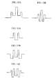
Also, an optical fiber shown in FIG. 11 having stepped refractive index profile in which
refractive indexes in two layers are different, and an optical fiber shown in FIGS. 12A and
12B having a segment refractive index profile in which a high refractive index section is
in the center part and a plurality of layers having different refractive indexes are disposed
are commonly used for a zero dispersion shift fiber in the 1.55µm bandwidth and a
non-zero dispersion shift fiber (hereinafter called NZ-DSF) which has been developed for
WDM data transmission.
For an optical fiber which is used for WDM data transfer, following
characteristics are required.
First, it is necessary to restrict a non-linear effect. Such a purpose can be
realized by enlarging an effective cross sectional area Aeff. Second, it is necessary to
restrict an occurrence of four-photon-mixture. Such a purpose can be realized by
obtaining a local dispersion. Third, it is necessary to restrict a linear distortion caused by
chromatic dispersion. Such a purpose can be realized by reducing an average chromatic
dispersion over an optical path. Lastly, in order to control dispersion in wide range
bandwidth, it can be realized by reducing the dispersion slope.
The above NZ-DSF was designed so as to be satisfied the required characteristics.
However, it is very difficult to enlarge the Aeff and reduce the dispersion slope
simultaneously. From a commercial point of view, an optical fiber (Aeff enlarged
NZ-DSF) in which Aeff is enlarged to 70 µ m2 and the dispersion slope is 0.09 ps/nm2/km,
and an optical fiber (low dispersion slope optical fiber) in which Aeff is 50 µm2 and the
dispersion slope is reduced to 0.05 ps/nm2/km, are commonly used for NZ-DSFs.
For an optical fiber which can realize more enlarged effective refractive index
Aeff and more reduced dispersion slope, an optical fiber shown in FIG. 13 having a
ring-shape refractive index profile in which a central part of the core has low refractive
index and high refractive index section therearound are disposed is known. For an
optical fiber having such a ring-shaped refractive index profile, an optical fiber in which
Aeff enlarged to 100 µm2 and the dispersion slope is restricted at 0.06 to 0.08 ps/nm2/km is
reported in "ECOC' 96 MoB. 3.2".
However, there has not been a report that an optical fiber having the ring-shape
refractive index profile can realize lower loss. For example, in the above report, 0.23
dB/km of loss has been reported. No other report mentions such lower loss
characteristics. Therefore, it is necessary to reduce the transmission loss so as to realize
an optical fiber having a ring-shaped profile.
In an optical fiber having conventional ring-shaped refractive index profile, an
absolute value for a chromatic dispersion in 1550 nm wavelength is set to zero or lower
than 6ps/nm/km. Chromatic dispersion such as 6ps/nm/km is in accordance with a
specification of a conventional NZ-DSF. The refractive index profile of an optical fiber
having such a chromatic dispersion area is shown in FIG. 14. Characteristics of this
optical fiber is shown in TABLE 1.
| TRANSMISSION LOSS | [dB/km] | 0.231 |
| CABLE CUTOFF WAVELENGTH λcc | [nm] | 1440 |
| EFFECTIVE CORE CROSS SECTIONAL AREA Aeff | [µm2] | 93.9 |
| MODE FIELD DIAMETER MFD | [µm] | 8.92 |
| CHROMATIC DISPERSION | [ps/nm/km] | 5.0 |
| DISPERSION SLOPE | [ps/nm2/km] | 0.071 |
| BENDING LOSS@20 | [dB/m] | 7.4 |
| POLARIZATION MODE DISPERSION PMD | [ps/√km] | 0.08 |
| * Above values are measured under condition of 1550 nm wavelength |
In FIG. 14, a horizontal axis indicates a distance from a center of the core in
radial direction. A vertical axis indicates a refractive index difference between each core
and the clad. Also, in FIG. 14, a product of a square of electric field E in a dominant
mode which transmits in an optical fiber and the distance r in the radial direction is shown
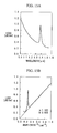
by dotted line. Also, in FIG. 15A, loss wavelength characteristics for wavelength λ is
shown. In FIG. 15B, loss value under condition that the unit of the horizontal axis is
l/λ4.
The transmission loss of this optical fiber in the 1550 nm wavelength is 0.231
dB/km. This transmission loss is as high as that of the optical fiber having conventional
ring-shaped refractive index profile. Also, value "a" which indicates an inclination to 1/λ4
is 1.183. Such a value is very large in contrast that a value "a" in an ordinary
NZ-DSF is nearly 1.06. Such a high transmission loss in the optical fiber is caused by
Rayleigh loss. In order to realize an optical fiber having low loss, it is necessary to
reduce the Rayleigh loss.
SUMMARY OF THE INVENTION
The present invention was made in consideration of the above problems. An
object of the present invention is to provide an optical fiber having an enlarged effective
cross sectional area, restricted dispersion slope, and low loss multiple ring-shaped
refractive index profile.
In order to solve the above problem, a first aspect of the present invention is an
optical fiber having a core containing two or more layers of which refractive indexes are
different such that one of the layer except a center part of the core has the largest refractive
index, wherein chromatic dispersion is between + 6 ps/nm/km or larger and smaller than +
15 ps/nm/km in 1550 nm wavelength, and transmission loss is smaller than 0.210 dB/km.
According to this feature, it is possible to realize low loss characteristics in an optical fiber
having ring-shaped refractive index profile.
A second aspect of the present invention is an optical fiber wherein the core
contains more than three layers of which refractive indexes are different.
A third aspect of the present invention is an optical fiber wherein refractive index
of a layer in center part of the core is lower than refractive index of a core.
A fourth aspect of the present invention is an optical fiber wherein an effective
cross sectional area in 1550 nm wavelength is larger than 90 µm2.
According to these features, it is possible to realize an optical fiber which can
restrict non-linear effect.
A fifth aspect of the present invention is an optical fiber wherein a dispersion
slope in the 1550 nm wavelength is less than 0.08 ps/nm2.
According to this feature, it is possible to control the dispersion over a wide range
of wavelength bandwidth; thus, it is possible to provide an optical fiber which can realize
high-speed high-quality optical data transmission.
A sixth aspect of the present invention is an optical fiber wherein refractive
indexes are different in four layers in the core, an effective cross sectional area is larger
than 90 µm2 in the 1550 nm, and the dispersion slope is smaller than 0.07 ps/nm2/km.
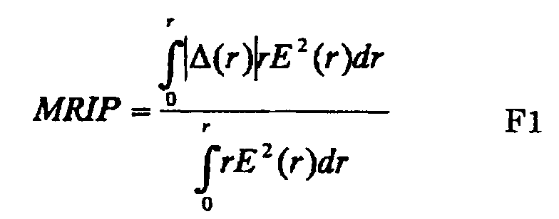
A seventh aspect of the present invention is an optical fiber having a power
product of the refractive index profile is smaller than 0.45 wherein the refractive index
profile is defined by a formula F1
under condition that r is a distance from a center of the core in a radial direction, Δ (r) is a
refractive index difference of the clad in a position of the distance r, E (r) is an electric
field distribution for dominant mode of a transmitted light in the position of the distance r.
According to this feature, it is possible to reduce Rayleigh loss; thus, it is possible
to realize an optical fiber having low loss characteristics.
As explained above, according to the present invention, an optical fiber is
produced so as to have a core containing two or more layers of which refractive indexes
are different such that one of the layer except a center part of the core has the largest
refractive index, wherein chromatic dispersion is between + 6 ps/nm/km or larger and
smaller than + 15 ps/nm/km in 1550 nm wavelength. Therefore, it is possible to realize
low loss characteristics in an optical fiber having ring-shaped refractive index profile.
Also, because an optical fiber is produced such that an effective cross sectional
area in 1550 nm wavelength is larger than 90 µm2. Therefore, it is possible to realize
an optical fiber which can restrict non-linear effect.
Also, because an optical fiber is produced such that a dispersion slope in the 1550
nm wavelength is less than 0.08 ps/nm2. Therefore, it is possible to control the
dispersion over a wide range of wavelength bandwidth; thus, it is possible to provide an
optical fiber which can realize high-speed high-quality optical data transmission.
Also, an optical fiber is produced so as to have a power product of the refractive
index profile which is smaller than 0.45. Therefore, it is possible to restrict the
transmission loss lower than 0.210 dB/km. Also, it is possible to reduce the loss caused
by the Rayleigh scattering; thus, it is possible to realize an optical fiber having low loss
characteristics.
BRIEF DESCRIPTION OF THE DRAWINGS
FIG. 1 is an example for refractive index profile of an optical fiber according to
the present invention.
FIG. 2 is a view showing a refractive index profile in an optical fiber according to
the present invention.
FIGS. 3A and 3B are showing an example of loss wavelength characteristics in
an optical fiber according to the present invention.
FIG. 4 is a graph for chromatic dispersion characteristics for an optical fiber
according to the present invention.
FIG. 5 is an example which is to be compared to the refractive index profile in an
optical fiber according to the present invention.
FIG. 6 is another example showing refractive index profile of an optical fiber
according to the present invention.
FIGS. 7A and 7B are examples to be compared to loss wavelength characteristics
of an optical fiber according to the present invention.
FIGS. 8A and 8B are showing another example for loss wavelength
characteristics of an optical fiber according to the present invention.
FIG. 9 is a view showing chromatic dispersion characteristics in a conventional
WDM optical fiber.
FIG. 10 is a view showing an example for a sigle-peak refractive index profile in
a conventional optical fiber.
FIG. 11 is a view showing an example for a stepped refractive index profile in a
conventional optical fiber.
FIGS. 12A and 12B are views showing an example for a segment core refractive
index profile in a conventional optical fiber.
FIGS. 13A to 13C are views showing an example for a ring-shaped refractive
index profile in a conventional optical fiber.
FIG. 14 is an example for refractive index profile in a conventional optical fiber.
FIGS. 15A and 15B are examples for loss wavelength characteristics in a
conventional optical fiber.
DETAILED DESCRIPTION OF THE INVENTION
The present invention is explained in detail as follows.
An optical fiber according to the present invention has a core containing two or
more layers of which refractive indexes are different such that one of the layer except a
center part of the core has the largest refractive index (hereinafter called ring-shaped
refractive index profile), wherein chromatic dispersion is between + 6 ps/nm/km or larger
and smaller than + 15 ps/nm/km in 1550 nm wavelength, and transmission loss is smaller
than 0.210 dB/km.
In such an optical fiber having a ring-shaped refractive index profile, it is
necessary to reduce the Rayleigh loss. For that purpose, the refractive index profile can
be more even than that of a conventional optical fiber by setting the chromatic dispersion
in 1550 nm wavelength to be in a range of +6 to +15 ps/nm/km which is larger than the
chromatic dispersion in a conventional NZ-DSF. That is, it is possible to reduce dopants
in an optical fiber; thus, Rayleigh loss can be reduced.
FIG. 1 shows a refractive index profile in an optical fiber under condition that the
optical fiber has chromatic dispersion which is almost the same refractive index profile
shown in FIG. 14 is designed to have more enlarged chromatic dispersion larger than +9
ps/nm/km. In FIG. 1, a horizontal axis indicates a distance from a center of the core in a
radial direction. A vertical axis indicates a refractive index difference for each core to
the clad. Also, in FIG. 1, a product of a square of electric field E in a dominant mode
which transmits in an optical fiber and the distance r in the radial direction is shown by
dotted line.
An example for refractive index profile in an optical fiber according to the
present invention is shown in FIG. 2. In FIG. 2, reference numeral 1 indicates a first
layer core section which is a center of the core. Reference numeral 2 indicates a second
layer core section which is formed around the first layer core section 1 so as to have
higher refractive index than that of the first layer core section 1. Reference numeral 3
indicates a third layer core section which is formed around the second layer core section 2
so as to have lower refractive index than that of the second layer core section 2.
Reference numeral 4 indicates a fourth layer core section which is formed around the third
layer core section 3 so as to have higher refractive index than that of the third layer core
section 3. Reference numeral 5 indicates a clad which is formed around the fourth layer
core section 4.
In this example, the refractive index in the first layer core section 1 and the
refractive index in the third layer core section 3 are lower than that in the clad 5. Also,
the refractive index in the second layer core section 2 is the highest. Here, the refractive
index difference in the first layer core section 1 is Δ 1 under condition that the refractive
index in the clad 5 is a reference point. Also, the refractive index difference in the
second layer core section 2 is Δ 2. The refractive index difference in the third layer core
section 3 is Δ3. The refractive index in the fourth layer core section 4 is Δ4. Under
such condition, absolute value for the refractive index difference Δ 1 in the first layer
core section 1 and the refractive index difference Δ 3 in the third layer core section 3
shown in FIG. 1 are smaller than that in the conventional optical fiber shown in FIG. 14.
An object of the present invention is to realize an optical fiber having low loss
characteristics. The loss in the optical fiber greatly depends on the Rayleigh scattering in
the optical fiber. Actually, the Rayleigh scattering caused in the optical fiber has a
relationship with amount of dopant in an area where the Rayleigh scattering occurs and
the electric field. For an index for indicating an influence caused by the Rayleigh
scattering, a Multiple of Refractive Index and Power (hereinafter called MRIP) which is
defined by a formula F1 is useful.
In formula F1, r indicates a distance from a center of the core in a radial direction.
Δ r is a refractive index difference for a clad. E(r) indicates distribution for electric field
of the dominant mode in the light which is transmitted.
In a conventional NZ-DSF shown in FIG. 14, MRIP is designed nearly at 0.5.
In contrast, in an optical fiber shown in FIG. 1, MRIP is 0.42. Thus, the MRIP is
reduced by nearly 10%. As explained in embodiments of the present invention later, it is
possible to reduce the transmission loss in a preferable level such as 0.210dB/km or lower
by reducing the Rayleigh loss.
In an optical fiber in this example, it is preferable the chromatic dispersion is
higher than +6ps/nm/km. If the chromatic dispersion is lower than +6ps/nm/km, it is
anticipated that the loss cannot be reduced sufficiently. Thus, by setting the chromatic
dispersion at +6ps/nm/km or higher, the chromatic dispersion does not become zero in the
S-Band; therefore, such optical fiber can be used for WDM data transmission.
Also, it is preferable the chromatic dispersion is lower than +15ps/nm/km. If the
chromatic dispersion is higher than +15ps/nm/km, it is possible to realize the same
characteristics even if a refractive index dispersion such as a single-peak refractive index
profile and a stepped refractive index profile is used instead of the ring-shaped refractive
index profile according to the present invention. That is, there is not merit in using an
optical fiber having the ring-shaped refractive index profile.
According to the optical fiber having a core containing two or more layers of
which refractive indexes are different such that one of the layer except a center part of the
core has the largest refractive index wherein chromatic dispersion is between + 6
ps/nm/km or larger and smaller than + 15 ps/nm/km in 1550 nm wavelength, it is possible
to realize an optical fiber having a ring-shaped refractive index profile with low loss
characteristics.
Also, because it is possible to make effective cross sectional area in the 1550 nm
wavelength larger than 90µm2, it is possible to realize an optical fiber which can restrict
the non-linear effect.
Also, because it is possible to make dispersion loss in the 1550 nm wavelength
smaller than 0.08ps/nm2/km, it is possible to realize an optical fiber which can control the
dispersion in wide range of the wavelength bandwidth; thus it is possible to realize
high-speed high-quality optical fiber for data transmission.
Also, by setting the MRIP at 0.45 or lower, it is possible to restrict the
transmission loss lower than 0.210 dB/km. Therefore, it is possible to reduce the loss
caused by the Rayleigh scattering; thus, it is possible to realize an optical fiber having low
loss characteristics.
Hereinafter, embodiments of an optical fiber according to the present invention
are shown with reference to drawings.
[First embodiment]
An optical fiber having refractive index profile shown in FIG. 1 is produced.
This optical fiber is manufactured such that an area (a) including a core in the optical fiber
having refractive index profile shown in FIG. 2 is produced by using Chemical Vapor
Disposition (hereinafter called CVD) method and an area (b) including a clad in the
optical fiber having refractive index profile shown in FIG. 2 is produced by using outside
vapor phase deposition method. Here, outer diameter of the clad in the optical fiber
which is produced is 125µm as shown in FIG. 2. In this optical fiber, the chromatic
dispersion is +8 ps/nm/km in 1550 nm wavelength which satisfies the requirement in
product designing aspect. The characteristics of this optical fiber is shown in FIG. 2.
| TRANSMISSION LOSS | [dB/km] | 0.206 |
| CABLE CUTOFF WAVELENGTH λcc | [nm] | 1450 |
| EFFECTIVE CORE CROSS SECTIONAL AREA Aeff | [µm2] | 100.6 |
| MODE FIELD DIAMETER MFD | [µm] | 9.26 |
| CHROMATIC DISPERSION | [ps/mn/km] | 8.0 |
| DISPERSION SLOPE | [ps/nm2/km] | 0.069 |
| BENDING LOSS@20 | [dB/m] | 10.5 |
| POLARIZATION MODE DISPERSION PMD | [ps/√km] | 0.07 |
| * Above values are measured under condition of 1550 nm wavelength |
Here, Aeff is approximately 100 µm2. Dispersion slope is 0.069ps/nm2/km.
Thus, it can be confirmed that Aeff is enlarged and the dispersion slope is reduced. In
addition, the transmission loss in the 1550 nm wavelength is 0.206 dB/km; thus,
0.02dB/km or more transmission loss is reduced comparing to the conventional optical
fiber having ring-shaped refractive index profile.
The loss wavelength characteristics for the wavelength λ in this optical fiber is
shown in FIG. 3A. The loss value under condition that the unit of the horizontal axis is
1/λ4 is shown in FIG. 3B. In FIG. 3 in which a graph is plotted by unit of 1/λ4, a value
which is indicated by "a" represents an inclination. In FIG. 3B, value "a" is 1.06.
Therefore, it is understood that the characteristics has been improved; thus, nearly the
same level as that of the conventional NZ-DSF of improvement has been achieved.
In FIG. 4, the chromatic dispersion characteristics in this optical fiber is shown.
The chromatic dispersion in the 1550 nm wavelength is +8ps/nm/km which is larger than
that of the conventional NZ-DSF. Also, the dispersion slope is restricted at
0.065ps/nm/km which can be understood to be fairly lower level. In this example, the
chromatic dispersion is +1ps/nm/km or more in the S-Band; therefore, not only the
C-Band and the L-Band, but also the S-Band can be used for data transmission.
[Second Embodiment]
An optical fiber having refractive index profile shown in FIGS. 5 and 6 is
produced.
FIG. 5 shows designed value for the refractive index profile in the conventional
NZ-DSF chromatic dispersion area. FIG. 6 shows a designed value for the refractive
index profile under condition that the chromatic dispersion is set to be nearly +9 ps/nm/km
which is larger than that of the conventional NZ-DSF. This optical fiber is manufactured
such that an area (a) including a core in the optical fiber having refractive index profile
shown in FIG. 2 is produced by using Chemical Vapor Disposition (hereinafter called
CVD) method and an area (b) including a clad in the optical fiber having refractive index
profile shown in FIG. 2 is produced by using outside vapor phase deposition method.
Here, outer diameter of the clad in the optical fiber which is produced is 125µm as shown
in FIG. 2.
In this example of optical fiber, by enlarging the chromatic dispersion to nearly
+9 ps/nm/km, the MRIP decreased from 0.50 to 0.43. The characteristics of this optical
fiber is shown in TABLES 3 and 4. TABLE 3 shows a characteristics of an optical fiber
having refractive index profile in the conventional NZ-DSF chromatic dispersion area as
shown in FIG. 5. TABLE 4 shows a characteristics of an optical fiber having refractive
index profile under condition that the chromatic dispersion shown in FIG. 6 is nearly +9
ps/nm/km.
| TRANSMISSION LOSS | [dB/km] | 0.230 |
| CABLE CUTOFF WAVELENGTH λcc | [nm] | 1452 |
| EFFECTIVE CORE CROSS SECTIONAL AREA Aeff | [µm2] | 95.4 |
| MODE FIELD DIAMETER MFD | [µm] | 8.59 |
| CHROMATIC DISPERSION | [ps/nm/km] | 4.4 |
| DISPERSION SLOPE | [ps/nm2/km] | 0.078 |
| BENDING LOSS@20 | [dB/m] | 9.5 |
| POLARIZATION MODE DISPERSION PMD | [ps/√km] | 0.05 |
| * Above values are measured under condition of 1550 nm wavelength |
| TRANSMISSION LOSS | [dB/km] | 0.202 |
| CABLE CUTOFF WAVELENGTH λ cc | [nm] | 1420 |
| EFFECTIVE CORE CROSS SECTIONAL AREA Aeff | [µm2] | 95.9 |
| MODE FIELD DIAMETER MFD | [µm] | 9.12 |
| CHROMATIC DISPERSION | [ps/nm/km] | 9.7 |
| DISPERSION SLOPE | [ps/nm2/km] | 0.070 |
| BENDING LOSS@20 | [dB/m] | 9.6 |
| POLARIZATION MODE DISPERSION PMD | [ps/√km] | 0.06 |
| * Above values are measured under condition of 1550 nm wavelength |
By enlarging the chromatic dispersion at +9 ps/nm/km, the transmission loss is
reduced from 0.230 dB/km to 0.202 dB/km.
In FIG. 7A, the loss wavelength characteristics for wavelength λ in an optical
fiber having refractive index profile in the conventional NZ-DSF chromatic dispersion
area is shown. In FIG. 7B, the loss value under condition that a horizontal axis indicates
1/λ4 is shown. According to these drawings in which a graph is plotted by unit of l/λ4,
a value which is indicated by "a" represents an inclination. Here, value "a" is 1.20. In
contrast, in FIG. 8A, loss wavelength characteristics for the wavelength λ in an optical
fiber having refractive index profile under condition that the chromatic dispersion is set at
nearly +9 ps/nm/km is shown. Also, in FIG. 8B, the loss value under condition that a
horizontal axis indicates 1/λ4 is shown. According to these drawings in which a graph is
plotted by unit of 1/λ4, a value which is indicated by "a" represents an inclination. Here,
value "a" is 1.052. Thus, it is understood that the loss characteristics has been improved.
In this embodiment, by setting the chromatic dispersion in a larger area than
that of a conventional optical fiber, it is confirmed that the loss caused by Rayleigh
scattering can be reduced.




 r is a distance from a center of the core in a radial direction,Δ (r) is a refractive index difference of the clad in a position of the distance r,E (r) is an electric field distribution for dominant mode of a transmitted light in the position of the distance r.