EP1336836A2 - X-ray CT scanner capable of logarithmic conversion - Google Patents
X-ray CT scanner capable of logarithmic conversion Download PDFInfo
- Publication number
- EP1336836A2 EP1336836A2 EP02257138A EP02257138A EP1336836A2 EP 1336836 A2 EP1336836 A2 EP 1336836A2 EP 02257138 A EP02257138 A EP 02257138A EP 02257138 A EP02257138 A EP 02257138A EP 1336836 A2 EP1336836 A2 EP 1336836A2
- Authority
- EP
- European Patent Office
- Prior art keywords
- function
- ray
- scanner
- conversion
- data
- Prior art date
- Legal status (The legal status is an assumption and is not a legal conclusion. Google has not performed a legal analysis and makes no representation as to the accuracy of the status listed.)
- Granted
Links
Images


Classifications
-
- A—HUMAN NECESSITIES
- A61—MEDICAL OR VETERINARY SCIENCE; HYGIENE
- A61B—DIAGNOSIS; SURGERY; IDENTIFICATION
- A61B6/00—Apparatus or devices for radiation diagnosis; Apparatus or devices for radiation diagnosis combined with radiation therapy equipment
-
- G—PHYSICS
- G01—MEASURING; TESTING
- G01N—INVESTIGATING OR ANALYSING MATERIALS BY DETERMINING THEIR CHEMICAL OR PHYSICAL PROPERTIES
- G01N23/00—Investigating or analysing materials by the use of wave or particle radiation, e.g. X-rays or neutrons, not covered by groups G01N3/00 – G01N17/00, G01N21/00 or G01N22/00
- G01N23/02—Investigating or analysing materials by the use of wave or particle radiation, e.g. X-rays or neutrons, not covered by groups G01N3/00 – G01N17/00, G01N21/00 or G01N22/00 by transmitting the radiation through the material
- G01N23/04—Investigating or analysing materials by the use of wave or particle radiation, e.g. X-rays or neutrons, not covered by groups G01N3/00 – G01N17/00, G01N21/00 or G01N22/00 by transmitting the radiation through the material and forming images of the material
- G01N23/046—Investigating or analysing materials by the use of wave or particle radiation, e.g. X-rays or neutrons, not covered by groups G01N3/00 – G01N17/00, G01N21/00 or G01N22/00 by transmitting the radiation through the material and forming images of the material using tomography, e.g. computed tomography [CT]
-
- G—PHYSICS
- G01—MEASURING; TESTING
- G01N—INVESTIGATING OR ANALYSING MATERIALS BY DETERMINING THEIR CHEMICAL OR PHYSICAL PROPERTIES
- G01N2223/00—Investigating materials by wave or particle radiation
- G01N2223/40—Imaging
- G01N2223/419—Imaging computed tomograph
-
- Y—GENERAL TAGGING OF NEW TECHNOLOGICAL DEVELOPMENTS; GENERAL TAGGING OF CROSS-SECTIONAL TECHNOLOGIES SPANNING OVER SEVERAL SECTIONS OF THE IPC; TECHNICAL SUBJECTS COVERED BY FORMER USPC CROSS-REFERENCE ART COLLECTIONS [XRACs] AND DIGESTS
- Y10—TECHNICAL SUBJECTS COVERED BY FORMER USPC
- Y10S—TECHNICAL SUBJECTS COVERED BY FORMER USPC CROSS-REFERENCE ART COLLECTIONS [XRACs] AND DIGESTS
- Y10S378/00—X-ray or gamma ray systems or devices
- Y10S378/901—Computer tomography program or processor
Definitions
- the present invention relates to an X-ray computed tomography scanner in which low-count data, which is acquired when an X-ray passes through object's regions whose X-ray absorption coefficients are relatively higher, is effectively used for CT image reconstruction.
- X-ray computed tomography is an imaging technique of producing density images based on X-ray absorption coefficients.
- An X-ray is radiated toward an object along various radiation angles to scan a section of the object so that resultant X-ray transmission amounts are measured, and X-ray absorption coefficients at each position in the object's section are computed. Using the coefficients, density images are produced. From a different viewpoint, it can be said that the X-ray CT makes use of the fact that the living body is composed of various tissues different in their X-ray absorption coefficients.
- regions in a scanned object's section such as bones, provide higher X-ray absorption coefficients.
- regions are also subjected to X-ray measurement, but amounts of X-ray from the regions, which are detected by an X-ray detector, are extremely low, thereby frequently causing a considerable amount of reduction in the SNR.
- An X-ray decays in strength exponentially while traveling through an object.
- An X-ray detector detects incoming X-rays and outputs signals in proportion to their transmission amounts.
- the output signals from the detector enter a data acquisition system (DAS), wherein the signal is amplified by amplifiers concurrently with being converted to digital signals by A/D converters.
- DAS data acquisition system
- noise components include random noise attributable to the detector and DAS.
- the random noise is normally negligible, differently from photon noise (serious noise caused by fluctuations in the number of incoming X-ray quantum particles). However, it is not always right to neglect the random noise. Particularly, in cases where, under particular conditions, such as scanning of thinner slices or scanning under lower X-ray amounts, X-rays that have been transmitted through paths of which X-ray absorption is large are detected by a detector, the random noise at the detector is often larger in strength than the photon noise. In such a case, the random noise becomes a dominant in the noise of the output from the detector.
- the signal that contains noise of an unnegligible level compared to an average level of the signal is called "low-count data.”
- the present invention has been made in consideration of the foregoing conventional problems, and an object of the present invention is to eliminates or suppress the low-count artifacts.
- an X-ray CT scanner comprising: an X-ray source generating an X-ray; a detector detecting the X-ray generated by the X-ray source and transmitted through an object; a processor producing projection data by applying to an output signal from the detector logarithm conversion processing on a function deviating from an ideal logarithm function; and a reconstruction unit configured to reconstruct an image using the projection data produced by the processor.
- An X-ray CT scanner according to the present invention will not stick to the conventional log conversion in producing projection data.
- the inventors' study into the log conversion revealed that an improved log conversion with the use of a function made to deviate positively in a certain manner from the ideal logarithm function is highly effective for "low-count data" acquired by the detector. It is therefore to eliminate or suppress low-count artifacts from or on reconstructed CT images.
- the function deviating from the ideal logarithm function consists of a function range assigned to the inputs equal to or larger than a specified value and defined by the ideal logarithm function, and a further function range assigned to the inputs less than the specified value and formed to have the deviating input/output characteristic.
- the function range and the further function range are defined individually and separated at a threshold given to the inputs.
- the function deviating from the ideal logarithm function is defined as a function providing one curve consisting of both of the function range and the further function range.
- the processor includes a table where input/output data of the one curve are stored and reference means configured to perform the logarithm conversion processing with reference to the input/output data stored in the table.
- the processor has weighting means configured to perform the logarithm conversion processing by performing weighted summation of plural log conversion results.
- the further function range is smaller in an angle of the input/output characteristic than the function range.
- X-ray CT scanners There are a variety of types of X-ray CT scanners, which includes a "rotate/rotate” type in which both of an X-ray tube and an X-ray detector rotate around an object as one unified member and a "stationary/rotate” type in which a multitude of detection elements arrayed on a ring are fixed but only an X-ray tube rotates around an object.
- the present invention can be applied to any type of X-ray CT scanner. The present embodiment will now be described about the rotate/rotate type of X-ray CT scanner, which is the current mainstream.
- an X-ray CT scanner has a gantry 100 including therein an X-ray tube 102, X-ray detector 103, and ling-like rotation member 102.
- the rotation member 102 is driven by a gantry driving unit 107 to rotate in a predetermined direction.
- On the rotation member 102 are provided the X-ray tube 102 and the X-ray detector 103 so that they are mutually faced.
- the X-ray tube 101 receives high-voltage pulses from a high-voltage generator 109 via a slip-ring 108, thereby generating X-rays a fan-beam or cone-beam form.
- the radiated X-rays are transmitted to pass through a field of view (FOV) of an object placed at an imaging region, and are received by the X-ray detector 103.
- FOV field of view
- the X-rays while traveling within the object, the X-rays decay exponentially correspondingly to X-ray absorption coefficients specific to bones, soft tissues, and/or others existing along their paths.
- the decayed X-rays then enter the X-ray detector 103.
- the X-ray detector 103 which is formed into a multiple channel type, is equipped with a plurality of detecting elements arrayed in an arc form centered at the focus of the X-ray tube 101.
- the detector 103 detects the incoming X-rays at a constant particular sampling frequency, thus allowing the incoming X-rays to be converted electrical signals (i.e., electrical current) in proportion to their amounts at every view angle.
- the direction along which the X-ray detecting elements are arrayed is called a channel direction
- the angular position of the X-ray tube 101 at each time of sampling is called a view angle
- the direction along which the view angle changes is called a view direction.
- the X-ray detector 103 can be formed into either a single type of detector or a multiple type of detector.
- the former is configured by arranging one line of plural detecting elements arrayed in the channel direction in a body-axis direction perpendicular to the channel direction.
- the latter is configured by arranging a plurality of such element lines in the body-axis direction.
- the electrical signals outputted from the X-ray detector 103 are sent to a data acquisition system (DAS), whereby the signals are converted into voltage signals, amplified, and converted to digital signals, before being sent a pre-processor 106 through an optical or magnetic non-contact data transmission unit 105.
- a contact type of transmission unit may be used in place of the non-contact data transmission unit 105.
- the data is normally compressed down to a lower number of bits (for example, 16 bits) or to a lower number of channels before sending it.
- the data is uncompressed up to its original number of bits or its original number of numbers.
- the acquired data should be subjected to a "log conversion" to obtain a total sum of X-ray absorption coefficients along each X-ray path, that is, X-ray projected information, because the X-rays have experienced exponential decays within an object during their travels.
- this log conversion is required by any type of X-ray CT scanner, the X-ray CT scanner of the present embodiment, to which the present invention is applied, adopts a log conversion of a different kind from the existing log conversion.
- the preprocessor 106 is in charge of decoding data or expanding data if the compression is made before sending the data to the preprocessor 106.
- the preprocessor 106 is configured to perform various kinds of correction.
- the correction includes offset correction, reference correction, and water correction.
- the offset correction is done to remove DC noise due to the DAS 104 (for instance, an input less than 1 is rounded up to 1).
- the reference correction is directed to eliminating fluctuations of the detected signals depending on changes in the view angle that is attributable for temporal changes in the X-ray output.
- This reference correction corrects acquired data on the basis of reference data detected with the aid of a reference detecting element.
- the water correction is subtraction of previously acquired water phantom data from the acquired data, resulting in that differences in sensitivity between channels of the X-ray detector 103 are suppressed so that the CT value of water becomes a reference value of zero.
- the data inputted to the preprocessor 106 (that is, the data just before being subjected to the log conversion and the various kinds of correction) is called “pure-raw data,” while the data outputted from the preprocessor 106 (that is, the data just after having experienced the log conversion and such kinds of correction and just being ready for reconstruction processing) is called “raw data.” Both the terms “pure-raw data” and “raw data” should be differentiated distinctively.
- the raw data from the preprocessor 106 is sent to a reconstruction unit 114, where the pre-processed raw data is used for reconstruction of CT images, such as tomographic images, three-dimensional surface images, and/or MPR (multi-planar reconstruction) images.
- Image data is then delivered to a display unit 116 to display images.
- the display unit 116 is accompanied by an input device (not shown) whereby a user is able to provide the scanner with necessary information such as various imaging conditions.
- a host controller 110 is responsible for control of the entire operations of the scanner, including scanning, relaying data, and processing of data.
- the preprocessor 106 will now be detailed, which is the most characteristic component in the scanner because the present invention is practiced into the preprocessor 106.
- the present invention which is applied to the X-ray CT scanner of this embodiment, is based on a concept that a logarithm function for conversion different from the conventional one is used. Considering this fact, why the conventional logarithm function is inconvenient will first be described, together with how the conversion using such logarithm function is made.
- the "low-count data” is data showing as larger fluctuations due to noise as unnegligible compared to an average signal level.
- the log conversion which is non-linear processing
- a conversion characteristic that has been expected is no longer obtained because of the noise. This problem derives from the fact the log conversion is depicted into a curve having a remarkable upward rise when drawn on input values (along the lateral axis) v.s. output values (along the vertical axis).
- the general log conversion processing is based on the following the formula (1).
- y K log [b, x] wherein a variable "x" is an input that corresponds to pure-raw data, and a variable y is an output that corresponds to pure data.
- a symbol “b” is the base of a logarithm, such as “e", "10” or others.
- the bottom is usually “2.”
- a symbol “K” is a scaling factor to define a range of the output values "y” in a desired manner for data processing, according to the base to be used or a range of the input values "x.”
- the logarithm function on the formula (1) is referred to as an "ideal logarithm function,” while a log conversion based on the “ideal logarithm function” is referred to as an “ideal log conversion” or "normal log conversion.”
- the present invention uses a function including a function region deviating from the ideal log function. For the reason that the remaining function range is, however, in accordance with the. "ideal log conversion,” the conversion processing with the aid of such function including a deviating function range is also called “log conversion,” like the case of the ideal log function.
- an input “x” is an average ⁇ x>, where the symbol “ ⁇ >” expresses an average.
- the gradient of the log conversion curve is more moderate for inputs equal to or larger than a value of ⁇ x>, while it is steeper for inputs less than the value of ⁇ x>, with the result that " ⁇ " is always greater than " ⁇ .”
- " ⁇ " is extremely different in value from " ⁇ .”
- the output "y” becomes a value of which noise component is more enhanced through the log conversion. This will bring about more enhanced low-count artifacts.
- the pure data that have been digitized and amplified by the data acquisition system 104 (and received the non-contact data transmission unit 105) are subject to the conversion processing on a function deviating from the normal logarithm function. Precisely, such conversion function of which range directed to the low-count data deviates from the ideal logarithm function.
- Fig. 2 details the preprocessor 106 in charge of performing the above log conversion according to the present invention.
- the preprocessor 106 other than the log conversion, it is preferred that an offset correction, reference correction, and water correction are performed, but those corrections are omitted from being detailed.
- the preprocessor 106 is equipped with an offset correcting unit 201, signal converter 202, reference correcting unit 203, and water correcting unit 204.
- the offset correcting unit 201 is used to remove DC noise generated and mixed at the DAS 104.
- the signal converter 202 which is an essential part for realizing the present invention, is in charge of conversion of low-count data based on a function deviating from the curve written by the ideal logarithm function.
- the reference correcting unit 203 is directed to a reference correction of a signal converted at the signal converter 202.
- the water correcting unit 204 is placed for a water correction of a signal coming from the reference correction unit 203.
- the signal converter 202 is provided with, as shown in Fig. 2, a discriminator 2021 for determining data using a threshold and a first and second converters 2022 and 2023 which are in charge of a log conversion respectively depending on the discriminated results at the discriminator 2021.
- the discriminator 2021 is configured to determine if data (i.e., pure-raw data) from the offset correcting unit 201 is low-count data or not with reference to a threshold, then supplies the pure-raw data to either the first or second converter 2022 or 2023 in compliance with the determined results.
- data i.e., pure-raw data
- the discriminator 2021 determines that the received pure-raw data is not low-count data, that is, it is non-low-count data, such data is sent to the first converter 2022, where the pure-raw data is subjected to log conversion based on the ideal logarithm function.
- the discriminator 2021 determines that the received pure-raw data belongs to low-count data, such data is sent to the second converter 2023.
- the pure-raw data is subjected to data conversion based on a function of which conversion values to the low-count data is different from the ideal logarithm function.
- the discriminator 2021 has a threshold to estimate whether pure- raw data is low-count data or not.
- the threshold is set in consideration of random noise from the detecting components such as photodiodes and DAS components such as DAS 104.
- the threshold is pre-set as a fixed value or specified as variable values.
- the threshold is specified in association with a variety of types of imaging conditions, such as a gain at the DAS 104 and/or the width of slices to be imaged.
- the threshold is changed in association with operative conditions of the DAS 104.
- the threshold for switching over the input to either the first or second converter 2022 or 2023 is changed in accord with imaging conditions. This makes it possible to steadily realize conversion processing in accord with imaging conditions including gains assigned to the DAS 104, whereby more deeply suppressing low-count artifacts.
- the threshold can be decided according to the gain.
- the threshold may be decided channel by channel.
- the discriminator 2021 is able to perform the determination on the threshold(s). That is, if the value of an input signal is equal to or greater than the threshold, the input is sent to the first converter 2022, while if the opposite case is realized, the input is sent to the second converter 2023.
- the first converter 2022 is in charge of the log conversion on the ideal logarithm function. Namely, when the input signals whose amplitudes are greater than the threshold (that is, non-low-count data) come from the discriminator 2021, the first converter 2022 performs the log conversion based on the ideal logarithm function according to the formula (1), which has been used conventionally.
- the second converter 2023 when the second converter 2023 will receive from the discriminator 2021 the input signals whose amplitudes are lower than the threshold, which is low-count data. The second converter 2023 then performs the log conversion based on a function whose region applied to the low-count data is different from the ideal logarithm function used by the first converter 2022.
- Such a function which differs from the ideal logarithm function and is in charge of the low-count data, should be connected, at a point of the threshold in a step-less manner, to part of the ideal logarithm function in charge of the non-low-count data.
- a function deviating from the ideal logarithm function should be lower in its curve gradient for most low-count data, in comparison with that of the ideal logarithm function.
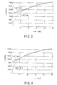
- Fig. 3 exemplifies, on condition that a threshold of "20" for the inputs is given at the discriminator 2021, an ideal logarithm function "1” employed by the first converter 1022 and the linear function "2" employed as a converting function by the second converter 2023.
- the linear function “2” uses, as its gradient “a,” a gradient (differential coefficient) of the function "1” obtained at the point of the threshold.
- the intercept “b” of the function "1” is decided so as to accomplish no separation between the two functions "1” and “2” at the point of the threshold.
- the threshold can be selected to some extent in a free manner. Further, the gradient “a” is not always limited to the differential coefficient of the function "1" at the point of the threshold.
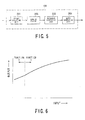
- Fig. 4 shows another example of such functions “1” and “2,” in which one function “1” is the ideal logarithm function and the other function “2” is realized by a linear function, on condition that the threshold is placed at a point "10" in the inputs. In this case, the function "1" is set to have a gradient "a" smaller than the differential coefficient of the function "1" at the threshold.
- the ideal logarithm function "1" shown in Figs. 3 and 4 has been used alone to perform the log conversion of the pure-raw data, which has further deteriorated the low-count data.
- the ideal logarithm function "1" is used for the log function.
- the function "2" deviating from the ideal logarithm function "1" is assigned to the log conversion of pure-raw data.
- the pure-raw data that has been log-converted are subjected to the remaining pro-processing (such as the reference correction and water correction), before being sent to the reconstruction unit 114 where the data is reconstructed into images.
- the remaining pro-processing such as the reference correction and water correction
- the present embodiment is characterized in that a function deviating from the ideal logarithm function is applied to only the low-count data (pure-raw data) from the detector.
- the discriminator 2021 is used to determine whether the pure-raw data is low-count data or not. If the low-count data is provided, the log conversion is carried out based on the second logarithm function (i.e., the linear function in the above embodiment). Meanwhile, when the non-low-count data is given, the log conversion is carried out on the first logarithm function (i.e., the ideal logarithm function), which differs from the second one.
- the low-count data is usually obtained when X-rays pass object's regions of which X-ray absorption coefficients are relatively higher, such as shoulders, back bones, or lumbar. Even when such low-count data undergoes the image reconstruction processing, low-count artifacts can steadily be eliminated or suppressed from or in the reconstructed images.
- the threshold is changed depending on imaging conditions, such as gains at the DAS 104, a field of view (FOV), and/or slice thicknesses (that is, pieces of information in which noise levels of the data acquisition components are reflected), the low-count artifacts in images can be reduced more steadily.
- the function "2" is changed as well.
- the function "2" is set to a linear function, at least one of its gradient and its intercept is changed responsively to changes in the value of the threshold.
- the two type of functions which are the first function used by the first converter 2022 and the second function used by the second converter 2023, can be replaced by only one type of function having the same effect as that described above. If such a configuration is adopted, the discriminator 2021 becomes unnecessary, while the first and second converters can be unified into one unit.
- the unified one conversion unit may be configured to have a single log conversion characteristic (i.e., a signal function) approximating to the entire solid-line curve shown in Fig. 3 or 4.
- a single function can be realized by a single n-th degree polynomial having a greater degree "n.”
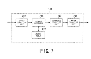
- the preprocessor 106 is provided with the offset correcting unit 201, a hanning filter 205, the reference correcting unit 203, and the water correcting unit 204 in this order.
- the units other than the hanning filter 205 are the same in the configurations as those shown before.
- the hanning filter 205 is responsible for a conversion (i.e., log conversion) based on a single- function input/output characteristic indicated as shown in Fig. 6 by a single curve smoothly connecting a function range tracing the ideal logarithm function "1" and a function range tracing the function "2" deviating from the ideal logarithm function "1.”
- the hanning filter 205 includes processing configurations for both the functions "1" and "2," although not shown in Fig. 6.
- the weighting "w,” which depends on the input "x,” becomes “1” when the input "x” is small, while it becomes “0” when the input "x” is large.
- weighting functions that provide such a smooth transition of weighting is a hanning function, so that, in the present modification, the conversion unit 205 is representatively called a "hanning filter.”
- the "hanning filter 205" permits both the functions "1" and “2” to be designed freely and connected to each other smoothly. This eliminates the necessity of employing the processing based on the threshold, and makes it possible to handle in a practical way both the functions (1) and (2) as a single function.
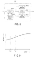
- the preprocessor 106 has a look-up processor 206 and a memory table 207, both of which are placed between the offset correcting unit 201 and the reference correcting unit 203.
- the memory table 207 values are memorized in a list form, which indicate the input/output characteristic of a single function formed by uniting the functions "1" and "2" shown in Fig. 6.
- the look-up processor 206 is configured to make reference to the input/output characteristic in the memory table 207, so that a log conversion of the signals from the offset correcting unit 201.
- the resultant log-converted data is then sent to the next reference correcting unit 203.
- the signal converter 202 is equipped with a discriminator 2024, threshold setting device 2025, and first to third converters 2026 to 2028.
- the threshold setting device 2025 is able to give, before the actual processing, the discriminator 2024 two thresholds TH1 and TH2 ( ⁇ TH1) to discriminate the input signals.
- the one curve shown in Fig. 9, which are obtained by uniting three or more functions, has two ranges.
- One range shows a function of which inputs are equal to or more than one threshold TH1 and which is in accordance with the ideal logarithm function "1."
- the other range which exists below the threshold TH1 for the inputs, complies with a function "2" deviating from the ideal logarithm function.
- the latter range according to the function "2" is further divided by the remaining threshold TH2.
- the region below the threshold TH2 is lower in the gradient than the range existing between the thresholds TH1 and TH2, thereby providing a gentler input/output characteristic.
- a modified configuration is also concerned with the signal converter 202 shown in Fig. 2.
- a plurality of types of converting functions which are set to at least one of the first function used in the first converter 2022 and the second function used in the second converter 2023, can be stored in their inner memories correspondingly to imaging conditions such as gains in the DAS 104, FOVs, and/or slice widths. And if a certain imaging condition is selected, the functions used in the first and/or second converters 2022 and 2023 can be switched over in conformity with the selected imaging condition. Concurrently, the thresholds may be changed in the same manner as above.
- the signal converter 202 is located to perform the log conversion with the pure-raw data sent from the detector, the position of the signal converter 202 may be changed to other ones, as long as the foregoing log conversion is assured.
- the signal converter 202 is located immediately after the reference correcting unit 203.
- the foregoing embodiment has adopted the configuration in which the pure-raw data outputted from the DAS 105 through the non-contact data transmission unit 105 is sequentially sent to the preprocessor 106, thus the raw data being produced in sequence.
- a memory unit as well as a data reading/writing circuit may be provided, so that acquired pure-raw data is stored in the memory unit as it is, differently from the preprocessing. This makes it possible that, if necessary, the acquired pure-raw data is again read from the memory unit for preprocessing the newly read pure-raw data and then reconstructing images from the newly preprocessed data.
Landscapes
- Health & Medical Sciences (AREA)
- Life Sciences & Earth Sciences (AREA)
- Engineering & Computer Science (AREA)
- General Health & Medical Sciences (AREA)
- Nuclear Medicine, Radiotherapy & Molecular Imaging (AREA)
- Medical Informatics (AREA)
- Radiology & Medical Imaging (AREA)
- Pathology (AREA)
- Physics & Mathematics (AREA)
- General Physics & Mathematics (AREA)
- Optics & Photonics (AREA)
- Analytical Chemistry (AREA)
- Chemical & Material Sciences (AREA)
- Immunology (AREA)
- Theoretical Computer Science (AREA)
- Biophysics (AREA)
- High Energy & Nuclear Physics (AREA)
- Pulmonology (AREA)
- Biochemistry (AREA)
- Biomedical Technology (AREA)
- Heart & Thoracic Surgery (AREA)
- Molecular Biology (AREA)
- Surgery (AREA)
- Animal Behavior & Ethology (AREA)
- Public Health (AREA)
- Veterinary Medicine (AREA)
- Apparatus For Radiation Diagnosis (AREA)
Abstract
Description
Claims (19)
- An X-ray CT scanner comprising
an X-ray source (101) generating an X-ray; and
a detector (103) detecting the X-ray generated by the X-ray source and transmitted through an object,
characterized in that the scanner further comprises
a processor (104-106) producing projection data by applying to an output signal from the detector logarithm conversion processing on a function (2) deviating from an ideal logarithm function (1) ; and
a reconstruction unit (114) configured to reconstruct an image using the projection data produced by the processor. - The X-ray CT scanner of claim 1, characterized in that
the ideal logarithm function is a logarithm function defined by a mathematical formula of y=K log[b, x] (wherein a variable x is an input, a variable y is an output, and a reference K shows a scaling constant),
wherein the function deviating from the ideal logarithm function is configured to have an input/output characteristic deviating from an input/output characteristic defined by the ideal logarithm function. - The X-ray CT scanner of claim 2, characterized in that
the function deviating from the ideal logarithm function consists of a function range assigned to the inputs equal to or larger than a specified value and defined by the ideal logarithm function, and
a further function range assigned to the inputs less than the specified value and formed to have the deviating input/output characteristic. - The X-ray CT scanner of claim 3, characterized in that
the function range and the further function range are defined individually and separated at a threshold given to the inputs. - The X-ray CT scanner of claim 3, characterized in that
the function deviating from the ideal logarithm function is defined as a function providing one curve consisting of both of the function range and the further function range. - The X-ray CT scanner of claim 5, characterized in that
the processor includes a table (207) where input/output data of the one curve are stored and reference means (206) configured to perform the logarithm conversion processing with reference to the input/output data stored in the table. - The X-ray CT scanner of claim 5, characterized in that
the processor has weighing means (205) configured to perform the logarithm conversion processing by performing weighted summation of plural log conversion results. - The X-ray CT scanner of claim 3, characterized in that
the further function range has a less steep inclination in the input/output characteristic than the ideal logarithm function at the inputs less than the specified value. - The X-ray CT scanner of claim 4, characterized in that
the further function range consists of a plurality of further function ranges divided at further one or more thresholds given to the inputs. - An X-ray CT scanner comprising
an X-ray source (101) generating an X-ray toward an object; and
a detector (103) detecting the X-ray transmitted from the object,
characterized in that the scanner further comprises
a processor (104-106) applying logarithm conversion processing to an output signal from the detector to produce projection data, the logarithm conversion processing being based on an ideal logarithm function (1) and a function (2) different from the ideal logarithm function; and
a reconstruction unit (114) configured to reconstruct an image using the projection data produced by the processor,
wherein the processor includes selection means (2021) configured to select either the ideal logarithm function or the function different from the ideal logarithm function, dependently on the output signal from the detector. - The X-ray CT scanner of claim 10, characterized in that
the function different from the ideal logarithm function is expressed by an n-th degree polynomial. - An X-ray CT scanner comprising;
an X-ray source (101) generating an X-ray toward an object; and
a detector (103) detecting the X-ray transmitted from the object,
characterized in that the scanner further comprises
a determining unit (2021) configured to determine if or not an output signal from the detector is low-count data;
a conversion processing unit (2022, 2023) configured to perform a conversion of the determined low-count data on a first conversion function (2) to produce projection data and to perform a conversion of non-low-count data on a second conversion function (1) different from the first conversion function to produce the projection data, the non-low-count-data being determined by the determining unit as data excluded from the low-count data, and
a reconstruction unit (114) configured to reconstruct an image using the projection data produced by the conversion processing unit. - The X-ray CT scanner of claim 12, characterized in that
the first conversion function is expressed by an n-th degree polynomial and the second conversion function is a mathematical logarithm function. - An X-ray CT scanner comprising
an X-ray source (101) generating an X-ray toward an object; and
a detector (103) detecting the X-ray transmitted from the object, characterized in that the scanner further comprises
a classifying unit (106, 2021) configured to use a threshold to classify whether an output signal from the detector is either low-count data or non-low-count data;
a conversion processing unit (106, 2022, 2023) configured to perform a conversion of the classified low-count data on a first conversion function (2) to produce projection data and to perform a conversion of the classified non-low-count data on a second conversion function (1) different from the first conversion function to produce the projection data; and
a reconstruction unit (114) configured to reconstruct an image using the projection data produced by the conversion processing unit. - The X-ray CT scanner of claim 14, characterized in that the threshold is variable.
- The X-ray CT scanner of claim 15, characterized in that the threshold is determined depending on an imaging condition.
- The X-ray CT scanner of claim 16, characterized in that the imaging condition is information about amplification of the output signal from detecting elements of the detector, the amplification being carried out at a data acquisition circuit (104), placed between the detector and the determining unit, for acquiring the signal.
- An X-ray CT scanner comprising
an X-ray source (101) generating an X-ray toward an object; and
a detector (103) detecting the X-ray transmitted from the object,
characterized in that the scanner further comprises
a storing unit (106, 2022, 2023) configured to store a plurality of types of conversion processing for converting the output signal from the detector on the functions;
a setting device (116) configured to set an imaging condition;
a determining unit (106, 202, 2024) configured to determine a threshold for switching the plurality of types of conversion functions stored in the storing unit depending on the imaging condition;
a conversion processing unit (106, 202, 2026-2028) configured to perform conversion processing with an output signal from the detector to produce projection data by using a conversion function switchably determined from the plurality of types of conversion functions by the determining unit; and
a reconstruction unit (114) configured to reconstruct an image using the projection data produced by the conversion processing unit. - The X-ray CT scanner of claim 18, characterized in that the threshold consists of a plurality of thresholds.
Applications Claiming Priority (4)
| Application Number | Priority Date | Filing Date | Title |
|---|---|---|---|
| JP2002041166 | 2002-02-19 | ||
| JP2002041166 | 2002-02-19 | ||
| JP2002287330 | 2002-09-30 | ||
| JP2002287330A JP4363834B2 (en) | 2002-02-19 | 2002-09-30 | X-ray computed tomography system |
Publications (3)
| Publication Number | Publication Date |
|---|---|
| EP1336836A2 true EP1336836A2 (en) | 2003-08-20 |
| EP1336836A3 EP1336836A3 (en) | 2004-04-21 |
| EP1336836B1 EP1336836B1 (en) | 2006-08-02 |
Family
ID=27624627
Family Applications (1)
| Application Number | Title | Priority Date | Filing Date |
|---|---|---|---|
| EP02257138A Expired - Lifetime EP1336836B1 (en) | 2002-02-19 | 2002-10-14 | X-ray CT scanner capable of logarithmic conversion |
Country Status (4)
| Country | Link |
|---|---|
| US (1) | US6829324B2 (en) |
| EP (1) | EP1336836B1 (en) |
| JP (1) | JP4363834B2 (en) |
| DE (1) | DE60213552T2 (en) |
Cited By (1)
| Publication number | Priority date | Publication date | Assignee | Title |
|---|---|---|---|---|
| WO2007082106A1 (en) * | 2006-01-05 | 2007-07-19 | Koninklijke Philips Electronics, N.V. | Artifact suppression |
Families Citing this family (17)
| Publication number | Priority date | Publication date | Assignee | Title |
|---|---|---|---|---|
| US7270227B2 (en) * | 2003-10-29 | 2007-09-18 | Lockheed Martin Corporation | Material handling system and method of use |
| US7183906B2 (en) * | 2004-03-19 | 2007-02-27 | Lockheed Martin Corporation | Threat scanning machine management system |
| US7212113B2 (en) * | 2004-05-04 | 2007-05-01 | Lockheed Martin Corporation | Passenger and item tracking with system alerts |
| US20050251398A1 (en) * | 2004-05-04 | 2005-11-10 | Lockheed Martin Corporation | Threat scanning with pooled operators |
| US20060282886A1 (en) * | 2005-06-09 | 2006-12-14 | Lockheed Martin Corporation | Service oriented security device management network |
| US7684421B2 (en) * | 2005-06-09 | 2010-03-23 | Lockheed Martin Corporation | Information routing in a distributed environment |
| US7961839B2 (en) * | 2005-12-15 | 2011-06-14 | Koninklijke Philips Electronics N.V. | Advanced convergence for multiple iterative algorithm |
| WO2007111669A2 (en) * | 2005-12-22 | 2007-10-04 | Visen Medical, Inc. | Combined x-ray and optical tomographic imaging system |
| US20080060910A1 (en) * | 2006-09-08 | 2008-03-13 | Shawn Younkin | Passenger carry-on bagging system for security checkpoints |
| US8260019B2 (en) | 2007-08-17 | 2012-09-04 | General Electric Company | Methods and apparatus for data communication across a slip ring |
| EP2493382B1 (en) * | 2009-10-29 | 2018-07-18 | Analogic Corporation | Three-dimensional scanner data compression |
| WO2011065079A1 (en) * | 2009-11-26 | 2011-06-03 | コニカミノルタエムジー株式会社 | Radiation imaging system and radiation imaging device |
| JP5788245B2 (en) * | 2011-07-06 | 2015-09-30 | 株式会社東芝 | X-ray CT system |
| WO2015115309A1 (en) * | 2014-01-28 | 2015-08-06 | 株式会社 日立メディコ | X-ray ct device and x-ray ct device image computation device |
| US10213176B2 (en) * | 2016-04-27 | 2019-02-26 | Toshiba Medical Systems Corporation | Apparatus and method for hybrid pre-log and post-log iterative image reconstruction for computed tomography |
| JP7258473B2 (en) * | 2018-05-01 | 2023-04-17 | キヤノンメディカルシステムズ株式会社 | X-ray CT device and imaging condition management device |
| CN113539440B (en) * | 2021-07-20 | 2023-11-21 | 东软医疗系统股份有限公司 | CT image reconstruction method and device, storage medium, computer equipment |
Family Cites Families (15)
| Publication number | Priority date | Publication date | Assignee | Title |
|---|---|---|---|---|
| JPS55156431A (en) * | 1979-05-24 | 1980-12-05 | Sony Corp | Noise reduction system |
| NL8202417A (en) | 1982-06-15 | 1984-01-02 | Philips Nv | APPARATUS AND METHOD FOR PROCESSING ROENTGEN IMAGES. |
| JPH0685565B2 (en) | 1985-11-14 | 1994-10-26 | コニカ株式会社 | X-ray film image reading method |
| JPH05261093A (en) | 1992-03-17 | 1993-10-12 | Toshiba Corp | Artifact correction method and its CT device |
| JP3408848B2 (en) * | 1993-11-02 | 2003-05-19 | 株式会社日立メディコ | Scattered X-ray correction method, X-ray CT apparatus, and multi-channel X-ray detector |
| JP3400063B2 (en) | 1994-02-15 | 2003-04-28 | 株式会社東芝 | Computer tomography equipment |
| JP3589769B2 (en) | 1995-12-19 | 2004-11-17 | 株式会社日立メディコ | X-ray CT system |
| JP3805107B2 (en) * | 1998-06-24 | 2006-08-02 | 株式会社日立メディコ | Measuring device using X-ray |
| US6055291A (en) * | 1998-08-25 | 2000-04-25 | General Electric Company | Systems, methods and apparatus for reconstructing images |
| US6201849B1 (en) * | 1999-08-16 | 2001-03-13 | Analogic Corporation | Apparatus and method for reconstruction of volumetric images in a helical scanning cone-beam computed tomography system |
| JP2001119583A (en) | 1999-10-21 | 2001-04-27 | Fuji Photo Film Co Ltd | Image information read method and device |
| US6385278B1 (en) * | 2000-04-28 | 2002-05-07 | Ge Medical Systems Global Technology Company, Llc | Method and apparatus for region of interest multislice CT scan |
| JP4805447B2 (en) | 2000-10-16 | 2011-11-02 | 株式会社東芝 | X-ray computed tomography system |
| US6415013B1 (en) * | 2000-12-28 | 2002-07-02 | Ge Medical Systems Global Technology Company, Llc | Backprojection methods and apparatus for computed tomography imaging systems |
| US6490335B1 (en) * | 2001-11-21 | 2002-12-03 | Ge Medical Systems Global Technologies Company Llc | Helical segment image reconstruction |
-
2002
- 2002-09-30 JP JP2002287330A patent/JP4363834B2/en not_active Expired - Fee Related
- 2002-10-11 US US10/269,070 patent/US6829324B2/en not_active Expired - Lifetime
- 2002-10-14 EP EP02257138A patent/EP1336836B1/en not_active Expired - Lifetime
- 2002-10-14 DE DE60213552T patent/DE60213552T2/en not_active Expired - Lifetime
Cited By (1)
| Publication number | Priority date | Publication date | Assignee | Title |
|---|---|---|---|---|
| WO2007082106A1 (en) * | 2006-01-05 | 2007-07-19 | Koninklijke Philips Electronics, N.V. | Artifact suppression |
Also Published As
| Publication number | Publication date |
|---|---|
| DE60213552D1 (en) | 2006-09-14 |
| JP4363834B2 (en) | 2009-11-11 |
| US20030156679A1 (en) | 2003-08-21 |
| DE60213552T2 (en) | 2007-10-04 |
| US6829324B2 (en) | 2004-12-07 |
| EP1336836A3 (en) | 2004-04-21 |
| JP2003310600A (en) | 2003-11-05 |
| EP1336836B1 (en) | 2006-08-02 |
Similar Documents
| Publication | Publication Date | Title |
|---|---|---|
| US6829324B2 (en) | X-ray CT scanner capable of performing improved log conversion | |
| JP4384749B2 (en) | Artifact correction for highly attenuating objects | |
| US6493416B1 (en) | Method and apparatus for noise reduction in computed tomographic systems | |
| JP4666915B2 (en) | Motion compensation for perfusion measurement | |
| US9532755B2 (en) | X-ray computed tomographic imaging apparatus and method for same | |
| JP2000308637A (en) | Image reconfiguration method of ct device | |
| US6408042B1 (en) | Methods and apparatus for cone beam artifact suppression in scanning imaging systems | |
| US7379575B2 (en) | Method for post- reconstructive correction of images of a computer tomograph | |
| Thielemans et al. | Image reconstruction of motion corrected sinograms | |
| CN112842370B (en) | Method and system for parametric noise modulation in X-ray imaging | |
| US7239730B2 (en) | Method and apparatus for volume scoring calcification concentrations of a CT scan | |
| US20020186809A1 (en) | Computer tomographic reconstruction with interpolation | |
| EP1468650B1 (en) | X-ray CT system and method with beam-hardening correction | |
| JP5329204B2 (en) | X-ray CT system | |
| JP3484288B2 (en) | X-ray tomography equipment | |
| US5533091A (en) | Noise suppression algorithm and system | |
| JPH10225453A (en) | Method and system for detecting blockage of a reference channel in a computed tomography system | |
| JPH10225452A (en) | Method and system for detecting partial volume artifacts | |
| US9980694B2 (en) | X-ray CT apparatus and image calculating device for X-ray CT apparatus | |
| EP3329851B1 (en) | Medical imaging apparatus and method of operating the same | |
| US6647084B1 (en) | Method and apparatus for filtering projection data of a helical scan | |
| US20230290022A1 (en) | Image generation device, medical device, and storage medium | |
| US20210090307A1 (en) | Medical image processing apparatus and medical image processing method | |
| US20100254585A1 (en) | Overexposure correction for large volume reconstruction in computed tomography apparatus | |
| US20050018889A1 (en) | Systems and methods for filtering images |
Legal Events
| Date | Code | Title | Description |
|---|---|---|---|
| PUAI | Public reference made under article 153(3) epc to a published international application that has entered the european phase |
Free format text: ORIGINAL CODE: 0009012 |
|
| 17P | Request for examination filed |
Effective date: 20021030 |
|
| AK | Designated contracting states |
Designated state(s): AT BE BG CH CY CZ DE DK EE ES FI FR GB GR IE IT LI LU MC NL PT SE SK TR |
|
| AX | Request for extension of the european patent |
Extension state: AL LT LV MK RO SI |
|
| PUAL | Search report despatched |
Free format text: ORIGINAL CODE: 0009013 |
|
| AK | Designated contracting states |
Kind code of ref document: A3 Designated state(s): AT BE BG CH CY CZ DE DK EE ES FI FR GB GR IE IT LI LU MC NL PT SE SK TR |
|
| AX | Request for extension of the european patent |
Extension state: AL LT LV MK RO SI |
|
| RIC1 | Information provided on ipc code assigned before grant |
Ipc: 7H 04N 5/217 B Ipc: 7G 01N 23/04 A |
|
| 17Q | First examination report despatched |
Effective date: 20040714 |
|
| AKX | Designation fees paid |
Designated state(s): DE FR GB NL |
|
| GRAP | Despatch of communication of intention to grant a patent |
Free format text: ORIGINAL CODE: EPIDOSNIGR1 |
|
| GRAS | Grant fee paid |
Free format text: ORIGINAL CODE: EPIDOSNIGR3 |
|
| GRAA | (expected) grant |
Free format text: ORIGINAL CODE: 0009210 |
|
| AK | Designated contracting states |
Kind code of ref document: B1 Designated state(s): DE FR GB NL |
|
| REG | Reference to a national code |
Ref country code: GB Ref legal event code: FG4D |
|
| REF | Corresponds to: |
Ref document number: 60213552 Country of ref document: DE Date of ref document: 20060914 Kind code of ref document: P |
|
| ET | Fr: translation filed | ||
| PLBE | No opposition filed within time limit |
Free format text: ORIGINAL CODE: 0009261 |
|
| STAA | Information on the status of an ep patent application or granted ep patent |
Free format text: STATUS: NO OPPOSITION FILED WITHIN TIME LIMIT |
|
| 26N | No opposition filed |
Effective date: 20070503 |
|
| REG | Reference to a national code |
Ref country code: GB Ref legal event code: 746 Effective date: 20090717 |
|
| REG | Reference to a national code |
Ref country code: FR Ref legal event code: PLFP Year of fee payment: 14 |
|
| REG | Reference to a national code |
Ref country code: FR Ref legal event code: PLFP Year of fee payment: 15 |
|
| REG | Reference to a national code |
Ref country code: GB Ref legal event code: 732E Free format text: REGISTERED BETWEEN 20160825 AND 20160831 Ref country code: NL Ref legal event code: PD Owner name: TOSHIBA MEDICAL SYSTEMS CORPORATION; JP Free format text: DETAILS ASSIGNMENT: VERANDERING VAN EIGENAAR(S), OVERDRACHT; FORMER OWNER NAME: KABUSHIKI KAISHA TOSHIBA Effective date: 20160627 |
|
| REG | Reference to a national code |
Ref country code: FR Ref legal event code: TP Owner name: TOSHIBA MEDICAL SYSTEMS CORPORATION, JP Effective date: 20160830 |
|
| REG | Reference to a national code |
Ref country code: DE Ref legal event code: R081 Ref document number: 60213552 Country of ref document: DE Owner name: TOSHIBA MEDICAL SYSTEMS CORPORATION, OTAWARA-S, JP Free format text: FORMER OWNER: KABUSHIKI KAISHA TOSHIBA, TOKYO, JP Ref country code: DE Ref legal event code: R082 Ref document number: 60213552 Country of ref document: DE Representative=s name: KRAMER BARSKE SCHMIDTCHEN PATENTANWAELTE PARTG, DE |
|
| REG | Reference to a national code |
Ref country code: FR Ref legal event code: PLFP Year of fee payment: 16 |
|
| REG | Reference to a national code |
Ref country code: FR Ref legal event code: PLFP Year of fee payment: 17 |
|
| PGFP | Annual fee paid to national office [announced via postgrant information from national office to epo] |
Ref country code: NL Payment date: 20191014 Year of fee payment: 18 Ref country code: DE Payment date: 20191001 Year of fee payment: 18 |
|
| PGFP | Annual fee paid to national office [announced via postgrant information from national office to epo] |
Ref country code: GB Payment date: 20191010 Year of fee payment: 18 |
|
| PGFP | Annual fee paid to national office [announced via postgrant information from national office to epo] |
Ref country code: FR Payment date: 20200914 Year of fee payment: 19 |
|
| REG | Reference to a national code |
Ref country code: DE Ref legal event code: R119 Ref document number: 60213552 Country of ref document: DE |
|
| REG | Reference to a national code |
Ref country code: NL Ref legal event code: MM Effective date: 20201101 |
|
| GBPC | Gb: european patent ceased through non-payment of renewal fee |
Effective date: 20201014 |
|
| PG25 | Lapsed in a contracting state [announced via postgrant information from national office to epo] |
Ref country code: DE Free format text: LAPSE BECAUSE OF NON-PAYMENT OF DUE FEES Effective date: 20210501 Ref country code: NL Free format text: LAPSE BECAUSE OF NON-PAYMENT OF DUE FEES Effective date: 20201101 |
|
| PG25 | Lapsed in a contracting state [announced via postgrant information from national office to epo] |
Ref country code: GB Free format text: LAPSE BECAUSE OF NON-PAYMENT OF DUE FEES Effective date: 20201014 |
|
| PG25 | Lapsed in a contracting state [announced via postgrant information from national office to epo] |
Ref country code: FR Free format text: LAPSE BECAUSE OF NON-PAYMENT OF DUE FEES Effective date: 20211031 |