EP1336819A2 - Applications avancées pour système lidar 3-D à balayage automatique - Google Patents
Applications avancées pour système lidar 3-D à balayage automatique Download PDFInfo
- Publication number
- EP1336819A2 EP1336819A2 EP03011685A EP03011685A EP1336819A2 EP 1336819 A2 EP1336819 A2 EP 1336819A2 EP 03011685 A EP03011685 A EP 03011685A EP 03011685 A EP03011685 A EP 03011685A EP 1336819 A2 EP1336819 A2 EP 1336819A2
- Authority
- EP
- European Patent Office
- Prior art keywords
- points
- site
- laser scanner
- location
- scan
- Prior art date
- Legal status (The legal status is an assumption and is not a legal conclusion. Google has not performed a legal analysis and makes no representation as to the accuracy of the status listed.)
- Granted
Links
Images


Classifications
-
- G—PHYSICS
- G01—MEASURING; TESTING
- G01B—MEASURING LENGTH, THICKNESS OR SIMILAR LINEAR DIMENSIONS; MEASURING ANGLES; MEASURING AREAS; MEASURING IRREGULARITIES OF SURFACES OR CONTOURS
- G01B11/00—Measuring arrangements characterised by the use of optical techniques
- G01B11/002—Measuring arrangements characterised by the use of optical techniques for measuring two or more coordinates
-
- G—PHYSICS
- G01—MEASURING; TESTING
- G01C—MEASURING DISTANCES, LEVELS OR BEARINGS; SURVEYING; NAVIGATION; GYROSCOPIC INSTRUMENTS; PHOTOGRAMMETRY OR VIDEOGRAMMETRY
- G01C11/00—Photogrammetry or videogrammetry, e.g. stereogrammetry; Photographic surveying
-
- G—PHYSICS
- G01—MEASURING; TESTING
- G01C—MEASURING DISTANCES, LEVELS OR BEARINGS; SURVEYING; NAVIGATION; GYROSCOPIC INSTRUMENTS; PHOTOGRAMMETRY OR VIDEOGRAMMETRY
- G01C15/00—Surveying instruments or accessories not provided for in groups G01C1/00 - G01C13/00
- G01C15/002—Active optical surveying means
-
- G—PHYSICS
- G01—MEASURING; TESTING
- G01S—RADIO DIRECTION-FINDING; RADIO NAVIGATION; DETERMINING DISTANCE OR VELOCITY BY USE OF RADIO WAVES; LOCATING OR PRESENCE-DETECTING BY USE OF THE REFLECTION OR RERADIATION OF RADIO WAVES; ANALOGOUS ARRANGEMENTS USING OTHER WAVES
- G01S17/00—Systems using the reflection or reradiation of electromagnetic waves other than radio waves, e.g. lidar systems
- G01S17/88—Lidar systems specially adapted for specific applications
- G01S17/89—Lidar systems specially adapted for specific applications for mapping or imaging
Definitions
- the present invention relates to a laser scanning system and, more particularly, to a method for operating a 3-D autoscanning LIDAR system.
- Computer models facilitate an understanding of the structure that is beneficial in a number of ways.
- One technique for constructing these computer models is to use a laser scanning system such as the system described in U.S. Patent Application No. 09/177,913.
- the '913 application is a continuation of 08/638,961 which, in turn, is a continuation of International Application No. PCT/US97/06793.
- Application '06793 has International Publication No. WO 97/40342.
- the '913 system includes a combination laser scanner and PC software system that measures, visualizes and models large structures and sites with high speed, high accuracy and over a large range.
- the device In use, the device is oriented towards the scene and the user selects the desired measurement area and measurement point spacing.
- a detailed 3-D geometry of exposed surfaces is remotely captured in the form of a dense, accurate, three dimensional point cloud.
- the '913 system includes a passively Q-switched pulsed laser.
- the laser beam is scanned over the target using computer-controlled galvo scanning mirrors.
- the system includes a video monitor for capturing the scene and displaying it on a computer such as a laptop. Using this video image, the operator can select the area to be scanned by the laser.
- the galvo mirrors direct the laser through repeated vertical scans, moving over horizontally after each vertical scan. By accurately monitoring the time of flight of each laser pulse out from the device and back into the device, exact positional information of the target can be calculated.
- Each measured point has associated with its 3-D information in the point cloud.
- the system software can display the point cloud to the user. As discussed herein in greater detail, the point cloud can be used to directly carry out a number of procedures. In addition, the system can process the point clouds into wire meshes, 3-D models and 2-D drawings for export to popular computer-aided design (CAD) rendering or other software.
- CAD computer-aided design
- the present invention provides a method for operating a laser scanner.
- the method includes the step of scanning a site with the laser scanner to create a field survey that has a number of scan points.
- the method also includes the step of creating a drawing of a structure that has a number of defined points that are positionally related to the scan points in the field survey.
- the method further includes the step of rescanning the site with the laser scanner to obtain rescan data.
- the rescan data corresponds to a number of the scan points.
- the method additionally includes the step of registering the rescan data with the defined points from the drawing to form registered data.
- the method also includes the steps of identifying a location of interest from the registered data, and illuminating a location at the site with a laser beam from the laser scanner that corresponds with the location of interest.
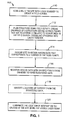
- FIG. 1 shows a flow chart 100 that illustrates an example of the operation of a laser scanner to facilitate construction planning and monitoring in accordance with the present invention.
- step 110 of FIG. 1 once a site has been selected, the site is scanned with the laser scanner to create a field survey. This information can then be provided to the architect or engineer who, in step 112, plans and designs the structure based on the highly accurate data provided by the scanner.
- the architect or engineer then creates a design drawing of the structure that has a number of defined points that are positionally related to the scan points in the field survey.
- the drawings can be downloaded into the system using well known methods of CAD exchange.
- the geometric information can be converted from one format to another.
- the system can help lay out the key features in the architect's design drawings on the actual construction site.
- the system would be brought back to the site.
- the site is rescanned with the scanner to obtain rescan data that corresponds to a number of the scan points.
- the site can be completely rescanned or partially rescanned.
- specific targets with known geometric relationships to the new design can also be rescanned.
- the rescan data which includes the cloud of points or the specific targets, is then registered with the architect's plans stored in the system software to form registered data.
- the process of registering the cloud of points or targets with the plans is well known in the art.
- Features in the scan data whether they be surveying monuments, targets, or simple features in a scene (such as the vertex at a corner) are matched with known locations (in the drawing coordinate system) to determine the required transformation between the rescanned data and the drawing data.
- the resulting transformation can then be used to map drawing locations to real world locations that can be identified by the scanner.
- locations of interest are identified from the registered data. For example, an operator can highlight a location of interest, such as a corner of a wall on the plans, on the display screen of the scanner.
- the system can illuminate the exact location in the field where the corner of the building is to be placed using the visible laser beam of the scanner as a marker.
- the targeting aspect of the laser can be used to trace out all key features from the plans on the actual site, both before and during construction.
- the visible laser can be used to target locations such as beams, doors or windows.
- the location of bolt holes could be marked.
- the laser is controlled by scanning mirrors, it is not limited to illuminating single point. Rather, the laser can actually draw geometric shapes, such as lines, rectangles or circles where doors or windows might need to be placed.
- an active or passive device can be used in conjunction with the laser system to identify points of interest that are located in open empty space.
- the active device would be carried by an operator who positions it in the path of the visible beam and walks with it along the beam until the exact range (i.e. the given point's position in space) is reached, at which time the device gives an audible or visual signal to the operator to stop and position a stake or a marker at that point in space.
- the passive device would be used in a similar manner, except that the notification of reaching the desired position is given by the system itself instead of the target. This is achieved, for example, by the passive target continually reflecting the laser beam back, and such returns are compared by the system to the correct range and a signal is given when the returned range is equal to the correct range of the desired point.
- the system can be used to periodically rescan the site.
- the site is rescanned with the laser scanner to obtain a number of rescan points that correspond to a number of the scan points and a number of the defined points.
- the rescan points are compared with the corresponding defined points.
- This information can then be used to monitor the progress of the construction by comparing the rescan with the design model to determine the quantity and percentage of the work completed.
- the quantities of objects placed since the beginning of construction and/or since the last scan ca be calculated and reported.
- the scanned data can be compared to the stored design plans to determine if there are any deviations.
- parts mating can be performed to determine if fabricated parts (which are usually fabricated at remote locations) will fit their designed or constructed support and tie points when delivered to the site.
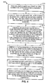
- FIG. 2 shows a flow chart 200 that illustrates an example of the operation of a laser scanner with constructed parts in accordance with the present invention.
- a site is scanned with a laser scanner to obtain a number of scan points that define a first structure, the scan points, in turn, include a number of first mating points.
- the scan points include a number of first mating points.
- a second structure built to be mated to the first structure is scanned to obtain a number of second mating points.
- the first mating points are then compared with the second mating points to determine if the second structure can be mated to the first structure.
- the system would also be quite helpful in remodels or revamps. For example, to the extent that work needs to be done on a certain feature such as a piping system in a refinery, the system can scan the desired area and model that piping system and objects in its surrounding area.
- the system can be used to model the piping and other pertinent objects in the area (such as pipe supports, vessels, etc.) to determine among other things, sizes, configuration, and locations.
- the designer armed with that information and information about the required modifications, can use the system to complete the design by adding to the model the additional piping, components, and structures required and removing any piping, components, etc., as required.
- a constructability analysis might need to be performed.
- FIG. 3 shows a flow chart 300 that illustrates an example of the operation of a laser scanner for a constructability analysis in accordance with the present invention.
- a site is scanned with a laser scanner to obtain a number of scan points that define an opening in a structure.
- an object to be placed within the structure is scanned to obtain a number of object points.
- the scan points are compared with the object points to determine if the object can be moved through the opening to be placed within the structure.
- the functionality of the system also lends itself to machine control functions. Machines are often controlled by robotic vision systems.
- the advantage of the device relates to its 3-D capabilities, long range capability, accuracy, detail, portability and software functionality.
- the system can be used to guide earth moving equipment such as a bulldozer or grader to perform its work much more efficiently than manual control by a human operator. The following examples of such utilization are given.
- FIG. 4 shows a flow chart 400 that illustrates an example of the operation of a laser scanner for controlling an earth mover in accordance with the present invention.
- a laser scanner which has a position in a coordinate system, is positioned on the tract of land to scan the tract of land.
- the tract of land is scanned with the laser scanner to define a plurality of first points on the natural surface of the tract of land. The first points have positions in the coordinate system and elevation measures of the project.
- a grading plan for the tract of land is generated by the design architect/engineer.
- the grading plan defines a to-be-constructed surface that differs from the natural surface.
- a plurality of second points are defined on the to-be-constructed surface.
- the second points have positions in the coordinate system and elevation measures of the project. Further, the surface described by the second points has a corresponding surface described by the first points.
- the elevation measures of specific points on the surface described by the second points are compared with the elevation measures of the corresponding points on the surface described by the first points to define cut points and fill points in the coordinate system.
- a cut point is defined when the elevation measure of a second point is less than the elevation measure of the corresponding first point, while a fill point is defined when the elevation measure of a second point is greater than the elevation measure of the corresponding first point.
- the system is used to perform an initial scan of the existing terrain, the scanned cloud of points is compared to the final design which is stored in the system, and the exact depth of cut/fill are determined at very close intervals throughout the terrain.
- this information is fed into an earth moving equipment that has a device which allows it to determine its location in space (in the coordinate system) at any given time (such as a GPS system).
- the earth mover is operated to form the constructed surface by removing earth from the cut points and adding earth to the fill points in response to the information derived from the comparison.
- the earth mover can be operated as described in U.S. Patent No. 5,631,658 which is hereby incorporated by reference. As a result, the combined information allows the equipment to be operated with little operator intervention.
- the system can also obtain its position by mounting the scanning system on the equipment. A scan of the original terrain is performed and cut/fill areas are determined as described above.
- the system being mounted on the earth moving equipment, can scan control targets or monuments placed on the ground (with known locations relative to the scan of the original terrain as well as to the new design). This information allows the system to guide the equipment without the use of other location devices, to perform its operations at the required locations and depth.
- the system can also be used in underground mining operations.
- the system mounted on a mine drilling equipment can scan the area to be drilled. This 3-D scan information will give the system detailed knowledge of the location of the equipment relative to the mine shaft/walls. This information coupled with information about the desired depth and extent of cut, allows the system to determine the required moves and guide the equipment to perform the task. After the task is done, the system can do a second scan from the new location and determine the amount of material excavated and create a 3-D map of the new excavated area. It is to be noted that the same functionality can be achieved without the system being mounted on the equipment, as long as it can be placed in a location where the equipment and the areas to be excavated are in its field of view.
- FIG. 5 shows a flow chart 500 that illustrates an example of the operation of a laser scanner for facilitating material handling in accordance with the present invention.
- a site is scanned with the laser scanner to obtain a number of scan points.
- objects within the site are identified by comparing the scan points to predefined geometric objects.
- commands are issued based on the identification of the objects.
- the system can be used to scan the yard and image the various containers in the yard.
- the system can be used to identify the type of container which is to be moved. Once the type of container is identified, the appropriate sling can then be selected for holding the container. Thereafter, the system can be used to accurately position the grappling mechanisms to pick up and move the container.
- the system can be used to guide robots in manufacturing and fabrication operations such as welding, cutting, painting, bin picking, etc. In shipping and similar cases, it can be used for ship or vehicle docking operations.
- the system also has the ability to be operated remotely. This use can free engineering and other staff from time consuming travel by commanding the system to perform scans remotely via a network or modem connection. A technician is needed at the site to be scanned to position the system at the desired location. Once that is done, the remote operator can perform all the required functions remotely. In this mode, the system can be also used to scan radio active areas or areas that are environmentally contaminated. In addition, this remote capability allows the system to be mounted on a remotely operated roving vehicle or robot.
- FIG. 6 shows a flow chart 600 that illustrates an example of the operation of a laser scanner for replicating existing parts in accordance with the present invention.
- an object is scanned with the laser scanner to obtain a number of object points.
- a model of the object is created from the object points.
- the model in turn, includes reproduction information.
- a reproducing machine is controlled in response to the reproduction information to reproduce the object.
- a custom bent pipe in a refinery or a ship needing replacement or duplication can be scanned.
- the system can produce rapidly an accurate model of the bent pipe and when connected to a computer controlled automated pipe bending (CNC) machine, can transfer that information to allow the machine to replicate the bend using a straight pipe.
- CNC computer controlled automated pipe bending
- the system can scan the bent pipe after the operation is performed to determine its conformance to the original.
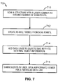
- FIG. 7 shows a flow chart 700 that illustrates an example of the operation of a laser scanner for creating repositories of information about various objects in accordance with the present invention.
- a structure is scanned with the laser scanner to obtain a number of scan points.
- an as-built model is created from the scan points.
- the model has a number of objects.
- data links are added to each object.
- the data links refer to externally available information available about the objects, and any number of types of data can be linked.
- a system user can view data from data links by opening a viewer appropriate for the type of data referred to by that particular link.
- the various objects in a model created from a scan can be tied to external database information which might give, for example, purchase information such as the age of a valve, when it was installed, the type of valve, the manufacturer, as well as other types of information.
- Another link to external information could provide access to the available inventory of replacement parts by accessing information in an external database, or any other source of online information.
- the inspection history or maintenance records could be linked into the object.
- the system can use bar codes or other similar passive or active devices attached to the objects being scanned to automatically acquire additional information about such objects such as model number, in service date, maintenance history, etc.
- the system acting as a "3-D browser" can allow users to view information contained in the data links stored within the object.
- the viewers are the appropriate programs for the particular data link. For example, a link to a vendors web site would be viewed by launching a web browser. A link to a drawing file would be viewed by opening the appropriate drawing viewer. A link to an external database would present the results directly in a window.
- the system is designed to include a server database which allows the model to be stored in a central location to be accessed by multiple users anywhere to work on the model, or use the model to access data or to launch other applications relating to the model or its objects.
- the system's database has locking and versioning capabilities to safeguard the integrity of the data while allowing multiple users to work on it simultaneously.
- the system includes sophisticated software capable of converting the 3-D cloud of points into CAD-type drawings.
- the cloud of points can be segmented into real world geometric figures. These geometric figures can then more easily be converted into CAD models.
- the 3-D point cloud can also be used directly to carry out a number of procedures without segmentation into geometric shapes. In some cases, the direct use of the point cloud can be more advantageous.
- each point in the cloud has coordinates associated therewith.
- the distances between each point can be directly determined from the data. These relationships permit many of the procedures discussed above to be performed directly from the point cloud. For example, comparing the progress of construction from one day or another can be done in comparing one set of point clouds to another set of point clouds.
- the data in the point clouds is very dense and, therefore, can provide additional information.
- the system can generate contours and cross sections from the cloud of points in real time. It can also develop 2-D plan, elevations, and sections directly and in real time from the cloud of points. In addition to collecting geometric information about scanned surfaces, the system also collects surface intensity information. This information allows the cloud of points to be used to identify and map surfaces of differing reflectance properties, such as rusting areas on object surfaces, and mineral areas on mine surfaces. This capability can also map sudden changes in surface normals such as the two sides of a cracked surface, and can also identify blemishes (such as gouges) in materials.
Applications Claiming Priority (5)
| Application Number | Priority Date | Filing Date | Title |
|---|---|---|---|
| US14369599P | 1999-07-14 | 1999-07-14 | |
| US143695P | 1999-07-14 | ||
| US09/615,439 US6619406B1 (en) | 1999-07-14 | 2000-07-13 | Advanced applications for 3-D autoscanning LIDAR system |
| US615439 | 2000-07-13 | ||
| EP00945404A EP1200801B1 (fr) | 1999-07-14 | 2000-07-14 | Procede d'actionnement d'un laser a balayage |
Related Parent Applications (1)
| Application Number | Title | Priority Date | Filing Date |
|---|---|---|---|
| EP00945404.2 Division | 2000-07-14 |
Publications (3)
| Publication Number | Publication Date |
|---|---|
| EP1336819A2 true EP1336819A2 (fr) | 2003-08-20 |
| EP1336819A3 EP1336819A3 (fr) | 2004-07-07 |
| EP1336819B1 EP1336819B1 (fr) | 2010-04-14 |
Family
ID=26841311
Family Applications (3)
| Application Number | Title | Priority Date | Filing Date |
|---|---|---|---|
| EP00945404A Expired - Lifetime EP1200801B1 (fr) | 1999-07-14 | 2000-07-14 | Procede d'actionnement d'un laser a balayage |
| EP04005717A Expired - Lifetime EP1426733B1 (fr) | 1999-07-14 | 2000-07-14 | Procédé pour niveler un terrain à l'aide d'une excavatrice commandée par un programme |
| EP03011685A Expired - Lifetime EP1336819B1 (fr) | 1999-07-14 | 2000-07-14 | Applications avancées pour système lidar 3-D à balayage automatique |
Family Applications Before (2)
| Application Number | Title | Priority Date | Filing Date |
|---|---|---|---|
| EP00945404A Expired - Lifetime EP1200801B1 (fr) | 1999-07-14 | 2000-07-14 | Procede d'actionnement d'un laser a balayage |
| EP04005717A Expired - Lifetime EP1426733B1 (fr) | 1999-07-14 | 2000-07-14 | Procédé pour niveler un terrain à l'aide d'une excavatrice commandée par un programme |
Country Status (6)
| Country | Link |
|---|---|
| US (3) | US6619406B1 (fr) |
| EP (3) | EP1200801B1 (fr) |
| JP (3) | JP4634681B2 (fr) |
| AT (3) | ATE464538T1 (fr) |
| DE (3) | DE60044210D1 (fr) |
| WO (1) | WO2001004576A1 (fr) |
Families Citing this family (194)
| Publication number | Priority date | Publication date | Assignee | Title |
|---|---|---|---|---|
| US6619406B1 (en) * | 1999-07-14 | 2003-09-16 | Cyra Technologies, Inc. | Advanced applications for 3-D autoscanning LIDAR system |
| US7395275B1 (en) * | 1999-11-16 | 2008-07-01 | Dana Automotive Systems Group, Llc | System and method for disposing of assets |
| DE10034035C2 (de) * | 2000-07-13 | 2002-10-31 | Hilti Ag | Markiervorrichtung und Verfahren zum visuellen Fixieren von Signalmarkierungen an vermessenen Flächen |
| JP3910582B2 (ja) * | 2001-07-31 | 2007-04-25 | 株式会社キャドセンター | 三次元構造物形状の自動生成装置、自動生成方法、そのプログラム、及びそのプログラムを記録した記録媒体 |
| US6759979B2 (en) | 2002-01-22 | 2004-07-06 | E-Businesscontrols Corp. | GPS-enhanced system and method for automatically capturing and co-registering virtual models of a site |
| JP4024719B2 (ja) * | 2003-04-14 | 2007-12-19 | 株式会社トプコン | 電子式測量装置 |
| JP4319857B2 (ja) * | 2003-05-19 | 2009-08-26 | 株式会社日立製作所 | 地図作成方法 |
| US20050063593A1 (en) * | 2003-09-19 | 2005-03-24 | Nelson James M. | Scalable method for rapidly detecting potential ground vehicle under cover using visualization of total occlusion footprint in point cloud population |
| US8294712B2 (en) * | 2003-09-19 | 2012-10-23 | The Boeing Company | Scalable method for rapidly detecting potential ground vehicle under cover using visualization of total occlusion footprint in point cloud population |
| US7725206B2 (en) * | 2003-11-12 | 2010-05-25 | The Boeing Company | System and method for manufacturing and after-market support using as-built data |
| US7158867B2 (en) * | 2003-11-28 | 2007-01-02 | Zoltan Filep | Computerized simultaneous laser marking and targeting system |
| GB0328420D0 (en) * | 2003-12-08 | 2004-01-14 | Pty Ltd | Modelling system |
| US20050157931A1 (en) * | 2004-01-15 | 2005-07-21 | Delashmit Walter H.Jr. | Method and apparatus for developing synthetic three-dimensional models from imagery |
| EP1743137A4 (fr) * | 2004-03-01 | 2008-06-25 | Ez 2 Cad Ltd | Systeme, procede et appareil de mesure, de positionnement et d'imagerie de surface sans fil au moyen d'un systeme de coordonnees portable |
| EP1600564A1 (fr) * | 2004-05-24 | 2005-11-30 | Leica Geosystems AG | Procédé pour contrôler un engin pour modifier des surfaces |
| US7236235B2 (en) * | 2004-07-06 | 2007-06-26 | Dimsdale Engineering, Llc | System and method for determining range in 3D imaging systems |
| US7697748B2 (en) * | 2004-07-06 | 2010-04-13 | Dimsdale Engineering, Llc | Method and apparatus for high resolution 3D imaging as a function of camera position, camera trajectory and range |
| US7571081B2 (en) | 2004-07-15 | 2009-08-04 | Harris Corporation | System and method for efficient visualization and comparison of LADAR point data to detailed CAD models of targets |
| US20060023204A1 (en) * | 2004-07-28 | 2006-02-02 | Zoltan Filep | Laser-GPS marking and targeting system |
| US7167252B2 (en) * | 2004-11-23 | 2007-01-23 | Kevin Gallup | Method and apparatus for creating cavities in packaging materials for artifacts, art objects and fragile or other valuable items |
| CN100337122C (zh) * | 2005-03-25 | 2007-09-12 | 浙江大学 | 无扫描器脉冲调制式三维成像方法及系统 |
| US20070247688A1 (en) * | 2006-01-18 | 2007-10-25 | Turner Mark A | Variable-beamwidth angle encoding laser scanner |
| US7894042B2 (en) * | 2006-01-18 | 2011-02-22 | Lockheed Martin Corporation | Omni-directional imaging sensor |
| RU2436796C9 (ru) | 2006-05-30 | 2013-12-27 | Дженентек, Инк. | Антитела и иммуноконъюгаты и их применения |
| US20080055554A1 (en) * | 2006-08-30 | 2008-03-06 | Keith Tubin | Full Scale Plan Projection |
| US20080104617A1 (en) * | 2006-11-01 | 2008-05-01 | Microsoft Corporation | Extensible user interface |
| JP5084398B2 (ja) * | 2007-08-24 | 2012-11-28 | キヤノン株式会社 | 測定装置、測定方法、及び、プログラム |
| US8315838B2 (en) * | 2008-03-04 | 2012-11-20 | The University Of Sydney | Method and system for exploiting information from heterogeneous sources |
| AU2009200859B2 (en) * | 2008-03-04 | 2014-08-07 | Technological Resources Pty. Limited | Scanning system for 3D mineralogy modelling |
| WO2010013266A1 (fr) * | 2008-07-30 | 2010-02-04 | Iride Italia S.R.L. | Appareil et procédé pour le désassemblage et le réassemblage d'une usine |
| US8031332B2 (en) * | 2008-11-20 | 2011-10-04 | Trimble Navigation Limited | Layout method |
| EP2194399A1 (fr) * | 2008-12-03 | 2010-06-09 | Leica Geosystems AG | Procédé de détermination de position et système de mesure géodésique |
| CA2753042C (fr) * | 2009-02-23 | 2017-10-24 | 2G Robotics Inc. | Ensemble dispositif de balayage a laser |
| CN101487896B (zh) * | 2009-02-23 | 2011-05-18 | 哈尔滨工业大学 | 指数增益调制距离成像器 |
| CN101487897B (zh) * | 2009-02-27 | 2011-08-17 | 哈尔滨工业大学 | Iccd增益正弦波调制无扫描速度成像器 |
| US9129236B2 (en) | 2009-04-17 | 2015-09-08 | The University Of Sydney | Drill hole planning |
| CN102460325A (zh) | 2009-05-01 | 2012-05-16 | 悉尼大学 | 集成式自动化系统 |
| PE20121019A1 (es) | 2009-05-01 | 2012-08-19 | Univ Sydney | Un sistema de control jerarquico para supervisar operaciones de un operador autonomo localizado dentro de una region geografica definida que contiene una o mas de zonas localizadas que tienen una delimitacion definida por operacion |
| WO2010124339A1 (fr) * | 2009-05-01 | 2010-11-04 | The University Of Sydney | Système d'automatisation intégré à système de compilation d'images |
| US9533418B2 (en) * | 2009-05-29 | 2017-01-03 | Cognex Corporation | Methods and apparatus for practical 3D vision system |
| JP5156693B2 (ja) * | 2009-06-17 | 2013-03-06 | 日立建機株式会社 | 産業車両のエンジン回転数制御装置 |
| US20110187704A1 (en) * | 2010-02-04 | 2011-08-04 | Microsoft Corporation | Generating and displaying top-down maps of reconstructed 3-d scenes |
| US8773424B2 (en) * | 2010-02-04 | 2014-07-08 | Microsoft Corporation | User interfaces for interacting with top-down maps of reconstructed 3-D scences |
| US8624902B2 (en) | 2010-02-04 | 2014-01-07 | Microsoft Corporation | Transitioning between top-down maps and local navigation of reconstructed 3-D scenes |
| US8558993B2 (en) | 2010-05-21 | 2013-10-15 | The National Institute of Standards and Technology, as Presented by the Secretary of Commerce | Optical frequency comb-based coherent LIDAR |
| JP5557609B2 (ja) * | 2010-06-15 | 2014-07-23 | 株式会社新世測量 | 三次元データ管理システム |
| JP5521833B2 (ja) * | 2010-06-30 | 2014-06-18 | ソニー株式会社 | 遠隔制御装置、遠隔制御設定方法及びプログラム |
| CN101975952A (zh) * | 2010-09-13 | 2011-02-16 | 天津市星际空间地理信息工程有限公司 | 一种机载lidar单片模式下的数字线划图半自动测图方法 |
| WO2012048456A1 (fr) | 2010-10-11 | 2012-04-19 | Empire Technology Development Llc | Modélisation d'objet |
| US8325351B2 (en) | 2010-10-29 | 2012-12-04 | Trimble Navigation Limited | Layout method |
| DE102011100919A1 (de) * | 2011-05-09 | 2012-11-15 | Lufthansa Technik Ag | Verfahren zur automatisierten Detektion von Einzelteilen einer komplexen differenziellen Struktur |
| US20130255977A1 (en) * | 2012-03-27 | 2013-10-03 | Caterpillar, Inc. | Control for Motor Grader Curb Operations |
| US9706185B2 (en) | 2012-04-16 | 2017-07-11 | Canrig Drilling Technology Ltd. | Device control employing three-dimensional imaging |
| US11871901B2 (en) | 2012-05-20 | 2024-01-16 | Cilag Gmbh International | Method for situational awareness for surgical network or surgical network connected device capable of adjusting function based on a sensed situation or usage |
| AU2013277928B2 (en) | 2012-06-18 | 2017-06-15 | Technological Resources Pty. Limited | Systems and methods for processing geophysical data |
| US9052721B1 (en) * | 2012-08-28 | 2015-06-09 | Google Inc. | Method for correcting alignment of vehicle mounted laser scans with an elevation map for obstacle detection |
| DE112014004641T5 (de) * | 2013-10-08 | 2016-08-18 | Nanyang Technological University | Verfahren und System für eine intelligente Kran-Hebebewegung |
| US10203399B2 (en) | 2013-11-12 | 2019-02-12 | Big Sky Financial Corporation | Methods and apparatus for array based LiDAR systems with reduced interference |
| CN103760517B (zh) * | 2014-01-14 | 2016-03-23 | 中国矿业大学 | 地下扫描卫星高精度跟踪定位方法及装置 |
| US9267837B2 (en) * | 2014-03-31 | 2016-02-23 | Siemens Industry, Inc. | Methods and systems for active load weight for mining excavating equipment |
| US9360554B2 (en) | 2014-04-11 | 2016-06-07 | Facet Technology Corp. | Methods and apparatus for object detection and identification in a multiple detector lidar array |
| CN103969656A (zh) * | 2014-05-08 | 2014-08-06 | 北京数字绿土科技有限公司 | 基于机载激光雷达的建筑物建模方法和装置 |
| US11504192B2 (en) | 2014-10-30 | 2022-11-22 | Cilag Gmbh International | Method of hub communication with surgical instrument systems |
| US9483863B2 (en) | 2014-12-05 | 2016-11-01 | Caterpillar Inc. | Terrain mapping system using moved material estimation |
| US10036801B2 (en) | 2015-03-05 | 2018-07-31 | Big Sky Financial Corporation | Methods and apparatus for increased precision and improved range in a multiple detector LiDAR array |
| US9866816B2 (en) | 2016-03-03 | 2018-01-09 | 4D Intellectual Properties, Llc | Methods and apparatus for an active pulsed 4D camera for image acquisition and analysis |
| JP6871695B2 (ja) * | 2016-08-05 | 2021-05-12 | 株式会社小松製作所 | 作業車両の制御システム、制御方法、及び作業車両 |
| JP7122802B2 (ja) * | 2016-08-05 | 2022-08-22 | 株式会社小松製作所 | 作業車両の制御システム、制御方法、及び作業車両 |
| US11487988B2 (en) | 2017-08-31 | 2022-11-01 | Ford Global Technologies, Llc | Augmenting real sensor recordings with simulated sensor data |
| US11455565B2 (en) | 2017-08-31 | 2022-09-27 | Ford Global Technologies, Llc | Augmenting real sensor recordings with simulated sensor data |
| EP3688410B1 (fr) * | 2017-09-26 | 2021-12-29 | Trimble AB | File d'attente de tâches de collecte de données pour instrument d'arpentage |
| US11564756B2 (en) | 2017-10-30 | 2023-01-31 | Cilag Gmbh International | Method of hub communication with surgical instrument systems |
| US11026687B2 (en) | 2017-10-30 | 2021-06-08 | Cilag Gmbh International | Clip applier comprising clip advancing systems |
| US11311342B2 (en) | 2017-10-30 | 2022-04-26 | Cilag Gmbh International | Method for communicating with surgical instrument systems |
| US11510741B2 (en) | 2017-10-30 | 2022-11-29 | Cilag Gmbh International | Method for producing a surgical instrument comprising a smart electrical system |
| US11317919B2 (en) | 2017-10-30 | 2022-05-03 | Cilag Gmbh International | Clip applier comprising a clip crimping system |
| US11911045B2 (en) | 2017-10-30 | 2024-02-27 | Cllag GmbH International | Method for operating a powered articulating multi-clip applier |
| US11291510B2 (en) | 2017-10-30 | 2022-04-05 | Cilag Gmbh International | Method of hub communication with surgical instrument systems |
| US11229436B2 (en) | 2017-10-30 | 2022-01-25 | Cilag Gmbh International | Surgical system comprising a surgical tool and a surgical hub |
| US11801098B2 (en) | 2017-10-30 | 2023-10-31 | Cilag Gmbh International | Method of hub communication with surgical instrument systems |
| US11129636B2 (en) | 2017-10-30 | 2021-09-28 | Cilag Gmbh International | Surgical instruments comprising an articulation drive that provides for high articulation angles |
| CN107944129A (zh) * | 2017-11-21 | 2018-04-20 | 北京恒华伟业科技股份有限公司 | 一种创建电缆模型的方法及装置 |
| US11132462B2 (en) | 2017-12-28 | 2021-09-28 | Cilag Gmbh International | Data stripping method to interrogate patient records and create anonymized record |
| US11045591B2 (en) | 2017-12-28 | 2021-06-29 | Cilag Gmbh International | Dual in-series large and small droplet filters |
| US11308075B2 (en) | 2017-12-28 | 2022-04-19 | Cilag Gmbh International | Surgical network, instrument, and cloud responses based on validation of received dataset and authentication of its source and integrity |
| US20190201039A1 (en) | 2017-12-28 | 2019-07-04 | Ethicon Llc | Situational awareness of electrosurgical systems |
| US11304745B2 (en) | 2017-12-28 | 2022-04-19 | Cilag Gmbh International | Surgical evacuation sensing and display |
| US11832899B2 (en) | 2017-12-28 | 2023-12-05 | Cilag Gmbh International | Surgical systems with autonomously adjustable control programs |
| US11389164B2 (en) | 2017-12-28 | 2022-07-19 | Cilag Gmbh International | Method of using reinforced flexible circuits with multiple sensors to optimize performance of radio frequency devices |
| US11109866B2 (en) | 2017-12-28 | 2021-09-07 | Cilag Gmbh International | Method for circular stapler control algorithm adjustment based on situational awareness |
| US11311306B2 (en) | 2017-12-28 | 2022-04-26 | Cilag Gmbh International | Surgical systems for detecting end effector tissue distribution irregularities |
| US10758310B2 (en) | 2017-12-28 | 2020-09-01 | Ethicon Llc | Wireless pairing of a surgical device with another device within a sterile surgical field based on the usage and situational awareness of devices |
| US11304720B2 (en) | 2017-12-28 | 2022-04-19 | Cilag Gmbh International | Activation of energy devices |
| US11257589B2 (en) | 2017-12-28 | 2022-02-22 | Cilag Gmbh International | Real-time analysis of comprehensive cost of all instrumentation used in surgery utilizing data fluidity to track instruments through stocking and in-house processes |
| US10943454B2 (en) | 2017-12-28 | 2021-03-09 | Ethicon Llc | Detection and escalation of security responses of surgical instruments to increasing severity threats |
| US10987178B2 (en) * | 2017-12-28 | 2021-04-27 | Ethicon Llc | Surgical hub control arrangements |
| US11423007B2 (en) | 2017-12-28 | 2022-08-23 | Cilag Gmbh International | Adjustment of device control programs based on stratified contextual data in addition to the data |
| US11896322B2 (en) | 2017-12-28 | 2024-02-13 | Cilag Gmbh International | Sensing the patient position and contact utilizing the mono-polar return pad electrode to provide situational awareness to the hub |
| US11410259B2 (en) | 2017-12-28 | 2022-08-09 | Cilag Gmbh International | Adaptive control program updates for surgical devices |
| US11147607B2 (en) | 2017-12-28 | 2021-10-19 | Cilag Gmbh International | Bipolar combination device that automatically adjusts pressure based on energy modality |
| US11096693B2 (en) | 2017-12-28 | 2021-08-24 | Cilag Gmbh International | Adjustment of staple height of at least one row of staples based on the sensed tissue thickness or force in closing |
| US11576677B2 (en) | 2017-12-28 | 2023-02-14 | Cilag Gmbh International | Method of hub communication, processing, display, and cloud analytics |
| US11589888B2 (en) | 2017-12-28 | 2023-02-28 | Cilag Gmbh International | Method for controlling smart energy devices |
| US20190201146A1 (en) | 2017-12-28 | 2019-07-04 | Ethicon Llc | Safety systems for smart powered surgical stapling |
| US11857152B2 (en) | 2017-12-28 | 2024-01-02 | Cilag Gmbh International | Surgical hub spatial awareness to determine devices in operating theater |
| US11464559B2 (en) | 2017-12-28 | 2022-10-11 | Cilag Gmbh International | Estimating state of ultrasonic end effector and control system therefor |
| US11291495B2 (en) | 2017-12-28 | 2022-04-05 | Cilag Gmbh International | Interruption of energy due to inadvertent capacitive coupling |
| US11818052B2 (en) | 2017-12-28 | 2023-11-14 | Cilag Gmbh International | Surgical network determination of prioritization of communication, interaction, or processing based on system or device needs |
| US11069012B2 (en) | 2017-12-28 | 2021-07-20 | Cilag Gmbh International | Interactive surgical systems with condition handling of devices and data capabilities |
| US11266468B2 (en) | 2017-12-28 | 2022-03-08 | Cilag Gmbh International | Cooperative utilization of data derived from secondary sources by intelligent surgical hubs |
| US11633237B2 (en) | 2017-12-28 | 2023-04-25 | Cilag Gmbh International | Usage and technique analysis of surgeon / staff performance against a baseline to optimize device utilization and performance for both current and future procedures |
| US11612444B2 (en) | 2017-12-28 | 2023-03-28 | Cilag Gmbh International | Adjustment of a surgical device function based on situational awareness |
| US11559308B2 (en) | 2017-12-28 | 2023-01-24 | Cilag Gmbh International | Method for smart energy device infrastructure |
| US10944728B2 (en) | 2017-12-28 | 2021-03-09 | Ethicon Llc | Interactive surgical systems with encrypted communication capabilities |
| US11937769B2 (en) | 2017-12-28 | 2024-03-26 | Cilag Gmbh International | Method of hub communication, processing, storage and display |
| US11786251B2 (en) | 2017-12-28 | 2023-10-17 | Cilag Gmbh International | Method for adaptive control schemes for surgical network control and interaction |
| US11273001B2 (en) | 2017-12-28 | 2022-03-15 | Cilag Gmbh International | Surgical hub and modular device response adjustment based on situational awareness |
| US11166772B2 (en) | 2017-12-28 | 2021-11-09 | Cilag Gmbh International | Surgical hub coordination of control and communication of operating room devices |
| US11253315B2 (en) | 2017-12-28 | 2022-02-22 | Cilag Gmbh International | Increasing radio frequency to create pad-less monopolar loop |
| US11424027B2 (en) | 2017-12-28 | 2022-08-23 | Cilag Gmbh International | Method for operating surgical instrument systems |
| US20190200981A1 (en) | 2017-12-28 | 2019-07-04 | Ethicon Llc | Method of compressing tissue within a stapling device and simultaneously displaying the location of the tissue within the jaws |
| US11304763B2 (en) | 2017-12-28 | 2022-04-19 | Cilag Gmbh International | Image capturing of the areas outside the abdomen to improve placement and control of a surgical device in use |
| US11051876B2 (en) | 2017-12-28 | 2021-07-06 | Cilag Gmbh International | Surgical evacuation flow paths |
| US11571234B2 (en) | 2017-12-28 | 2023-02-07 | Cilag Gmbh International | Temperature control of ultrasonic end effector and control system therefor |
| US11419667B2 (en) | 2017-12-28 | 2022-08-23 | Cilag Gmbh International | Ultrasonic energy device which varies pressure applied by clamp arm to provide threshold control pressure at a cut progression location |
| US11540855B2 (en) | 2017-12-28 | 2023-01-03 | Cilag Gmbh International | Controlling activation of an ultrasonic surgical instrument according to the presence of tissue |
| US11304699B2 (en) | 2017-12-28 | 2022-04-19 | Cilag Gmbh International | Method for adaptive control schemes for surgical network control and interaction |
| US10932872B2 (en) | 2017-12-28 | 2021-03-02 | Ethicon Llc | Cloud-based medical analytics for linking of local usage trends with the resource acquisition behaviors of larger data set |
| US11076921B2 (en) | 2017-12-28 | 2021-08-03 | Cilag Gmbh International | Adaptive control program updates for surgical hubs |
| US11432885B2 (en) | 2017-12-28 | 2022-09-06 | Cilag Gmbh International | Sensing arrangements for robot-assisted surgical platforms |
| US11744604B2 (en) | 2017-12-28 | 2023-09-05 | Cilag Gmbh International | Surgical instrument with a hardware-only control circuit |
| US10892995B2 (en) | 2017-12-28 | 2021-01-12 | Ethicon Llc | Surgical network determination of prioritization of communication, interaction, or processing based on system or device needs |
| US11364075B2 (en) | 2017-12-28 | 2022-06-21 | Cilag Gmbh International | Radio frequency energy device for delivering combined electrical signals |
| US11179208B2 (en) | 2017-12-28 | 2021-11-23 | Cilag Gmbh International | Cloud-based medical analytics for security and authentication trends and reactive measures |
| US11160605B2 (en) | 2017-12-28 | 2021-11-02 | Cilag Gmbh International | Surgical evacuation sensing and motor control |
| US11317937B2 (en) | 2018-03-08 | 2022-05-03 | Cilag Gmbh International | Determining the state of an ultrasonic end effector |
| US11903601B2 (en) | 2017-12-28 | 2024-02-20 | Cilag Gmbh International | Surgical instrument comprising a plurality of drive systems |
| US11202570B2 (en) | 2017-12-28 | 2021-12-21 | Cilag Gmbh International | Communication hub and storage device for storing parameters and status of a surgical device to be shared with cloud based analytics systems |
| US20190201139A1 (en) | 2017-12-28 | 2019-07-04 | Ethicon Llc | Communication arrangements for robot-assisted surgical platforms |
| US11464535B2 (en) | 2017-12-28 | 2022-10-11 | Cilag Gmbh International | Detection of end effector emersion in liquid |
| US11666331B2 (en) | 2017-12-28 | 2023-06-06 | Cilag Gmbh International | Systems for detecting proximity of surgical end effector to cancerous tissue |
| US11559307B2 (en) | 2017-12-28 | 2023-01-24 | Cilag Gmbh International | Method of robotic hub communication, detection, and control |
| US11896443B2 (en) | 2017-12-28 | 2024-02-13 | Cilag Gmbh International | Control of a surgical system through a surgical barrier |
| US11864728B2 (en) | 2017-12-28 | 2024-01-09 | Cilag Gmbh International | Characterization of tissue irregularities through the use of mono-chromatic light refractivity |
| US11786245B2 (en) | 2017-12-28 | 2023-10-17 | Cilag Gmbh International | Surgical systems with prioritized data transmission capabilities |
| US11832840B2 (en) | 2017-12-28 | 2023-12-05 | Cilag Gmbh International | Surgical instrument having a flexible circuit |
| US11056244B2 (en) | 2017-12-28 | 2021-07-06 | Cilag Gmbh International | Automated data scaling, alignment, and organizing based on predefined parameters within surgical networks |
| US11324557B2 (en) | 2017-12-28 | 2022-05-10 | Cilag Gmbh International | Surgical instrument with a sensing array |
| US11419630B2 (en) | 2017-12-28 | 2022-08-23 | Cilag Gmbh International | Surgical system distributed processing |
| US11100631B2 (en) | 2017-12-28 | 2021-08-24 | Cilag Gmbh International | Use of laser light and red-green-blue coloration to determine properties of back scattered light |
| US11278281B2 (en) | 2017-12-28 | 2022-03-22 | Cilag Gmbh International | Interactive surgical system |
| US11234756B2 (en) | 2017-12-28 | 2022-02-01 | Cilag Gmbh International | Powered surgical tool with predefined adjustable control algorithm for controlling end effector parameter |
| US10966791B2 (en) | 2017-12-28 | 2021-04-06 | Ethicon Llc | Cloud-based medical analytics for medical facility segmented individualization of instrument function |
| US11376002B2 (en) | 2017-12-28 | 2022-07-05 | Cilag Gmbh International | Surgical instrument cartridge sensor assemblies |
| US20190201118A1 (en) | 2017-12-28 | 2019-07-04 | Ethicon Llc | Display arrangements for robot-assisted surgical platforms |
| US11026751B2 (en) | 2017-12-28 | 2021-06-08 | Cilag Gmbh International | Display of alignment of staple cartridge to prior linear staple line |
| US11659023B2 (en) | 2017-12-28 | 2023-05-23 | Cilag Gmbh International | Method of hub communication |
| US11529187B2 (en) | 2017-12-28 | 2022-12-20 | Cilag Gmbh International | Surgical evacuation sensor arrangements |
| US11446052B2 (en) | 2017-12-28 | 2022-09-20 | Cilag Gmbh International | Variation of radio frequency and ultrasonic power level in cooperation with varying clamp arm pressure to achieve predefined heat flux or power applied to tissue |
| US10892899B2 (en) | 2017-12-28 | 2021-01-12 | Ethicon Llc | Self describing data packets generated at an issuing instrument |
| US11678881B2 (en) | 2017-12-28 | 2023-06-20 | Cilag Gmbh International | Spatial awareness of surgical hubs in operating rooms |
| US10849697B2 (en) | 2017-12-28 | 2020-12-01 | Ethicon Llc | Cloud interface for coupled surgical devices |
| US11284936B2 (en) | 2017-12-28 | 2022-03-29 | Cilag Gmbh International | Surgical instrument having a flexible electrode |
| US11179175B2 (en) | 2017-12-28 | 2021-11-23 | Cilag Gmbh International | Controlling an ultrasonic surgical instrument according to tissue location |
| US11602393B2 (en) | 2017-12-28 | 2023-03-14 | Cilag Gmbh International | Surgical evacuation sensing and generator control |
| EP3533934B1 (fr) | 2018-03-01 | 2020-07-15 | BAUER Spezialtiefbau GmbH | Procédé de construction |
| US11389188B2 (en) | 2018-03-08 | 2022-07-19 | Cilag Gmbh International | Start temperature of blade |
| US11589915B2 (en) | 2018-03-08 | 2023-02-28 | Cilag Gmbh International | In-the-jaw classifier based on a model |
| US11259830B2 (en) | 2018-03-08 | 2022-03-01 | Cilag Gmbh International | Methods for controlling temperature in ultrasonic device |
| US11207067B2 (en) | 2018-03-28 | 2021-12-28 | Cilag Gmbh International | Surgical stapling device with separate rotary driven closure and firing systems and firing member that engages both jaws while firing |
| US11219453B2 (en) | 2018-03-28 | 2022-01-11 | Cilag Gmbh International | Surgical stapling devices with cartridge compatible closure and firing lockout arrangements |
| US11259806B2 (en) | 2018-03-28 | 2022-03-01 | Cilag Gmbh International | Surgical stapling devices with features for blocking advancement of a camming assembly of an incompatible cartridge installed therein |
| US11471156B2 (en) | 2018-03-28 | 2022-10-18 | Cilag Gmbh International | Surgical stapling devices with improved rotary driven closure systems |
| US11090047B2 (en) | 2018-03-28 | 2021-08-17 | Cilag Gmbh International | Surgical instrument comprising an adaptive control system |
| US11278280B2 (en) | 2018-03-28 | 2022-03-22 | Cilag Gmbh International | Surgical instrument comprising a jaw closure lockout |
| US11096688B2 (en) | 2018-03-28 | 2021-08-24 | Cilag Gmbh International | Rotary driven firing members with different anvil and channel engagement features |
| US11213294B2 (en) | 2018-03-28 | 2022-01-04 | Cilag Gmbh International | Surgical instrument comprising co-operating lockout features |
| US10973520B2 (en) | 2018-03-28 | 2021-04-13 | Ethicon Llc | Surgical staple cartridge with firing member driven camming assembly that has an onboard tissue cutting feature |
| GB2572781B (en) * | 2018-04-10 | 2023-01-04 | E M & I Maritime Ltd | Inspection Method And Associated Apparatus |
| US11002075B1 (en) | 2018-07-31 | 2021-05-11 | J.H. Fletcher & Co. | Mine drilling system and related method |
| US11769117B2 (en) * | 2019-01-18 | 2023-09-26 | Johnson Controls Tyco IP Holdings LLP | Building automation system with fault analysis and component procurement |
| US11464511B2 (en) | 2019-02-19 | 2022-10-11 | Cilag Gmbh International | Surgical staple cartridges with movable authentication key arrangements |
| US11357503B2 (en) | 2019-02-19 | 2022-06-14 | Cilag Gmbh International | Staple cartridge retainers with frangible retention features and methods of using same |
| US11369377B2 (en) | 2019-02-19 | 2022-06-28 | Cilag Gmbh International | Surgical stapling assembly with cartridge based retainer configured to unlock a firing lockout |
| US11291444B2 (en) | 2019-02-19 | 2022-04-05 | Cilag Gmbh International | Surgical stapling assembly with cartridge based retainer configured to unlock a closure lockout |
| US11317915B2 (en) | 2019-02-19 | 2022-05-03 | Cilag Gmbh International | Universal cartridge based key feature that unlocks multiple lockout arrangements in different surgical staplers |
| DE102019112535A1 (de) * | 2019-05-14 | 2020-11-19 | Innogy Se | Projektionsvorrichtung für Tiefbauarbeiten sowie zum Verfahren zum Steuern von Tiefbauarbeiten |
| USD950728S1 (en) | 2019-06-25 | 2022-05-03 | Cilag Gmbh International | Surgical staple cartridge |
| USD964564S1 (en) | 2019-06-25 | 2022-09-20 | Cilag Gmbh International | Surgical staple cartridge retainer with a closure system authentication key |
| USD952144S1 (en) | 2019-06-25 | 2022-05-17 | Cilag Gmbh International | Surgical staple cartridge retainer with firing system authentication key |
| CN110345968A (zh) * | 2019-07-18 | 2019-10-18 | 南京市测绘勘察研究院股份有限公司 | 一种对移动三维激光扫描隧道成果里程配付的方法 |
| US11556000B1 (en) | 2019-08-22 | 2023-01-17 | Red Creamery Llc | Distally-actuated scanning mirror |
| CN112923865A (zh) * | 2019-12-06 | 2021-06-08 | 广州方舆科技有限公司 | 建筑三维激光测绘数据采集传输处理的方法及系统 |
| EP3881968A1 (fr) * | 2020-03-17 | 2021-09-22 | Fraisa SA | Procédé de détermination de l'état d'usure d'un outil |
Citations (2)
| Publication number | Priority date | Publication date | Assignee | Title |
|---|---|---|---|---|
| DE19543299A1 (de) | 1995-11-21 | 1997-05-22 | Wilhelm Kapfer | Verfahren und Vorrichtung zum Vermessen von Gegenständen |
| WO1997040342A2 (fr) | 1996-04-24 | 1997-10-30 | Cyra Technologies, Inc. | Systeme integre d'imagerie et de modelisation d'objets tridimensionnels rapidement et avec precision |
Family Cites Families (34)
| Publication number | Priority date | Publication date | Assignee | Title |
|---|---|---|---|---|
| JPS5596475A (en) * | 1979-01-19 | 1980-07-22 | Nissan Motor Co Ltd | Obstacle detector for vehicle |
| EP0218750A1 (fr) | 1985-10-18 | 1987-04-22 | Gruber, Dietfried, Dipl.-Ing.Architekt | Procédé et dispositif pour effectuer des mesures géodésiques |
| US4918627A (en) | 1986-08-04 | 1990-04-17 | Fmc Corporation | Computer integrated gaging system |
| US4820041A (en) * | 1986-11-12 | 1989-04-11 | Agtek Development Co., Inc. | Position sensing system for surveying and grading |
| JP2831110B2 (ja) | 1990-09-05 | 1998-12-02 | 三菱重工業株式会社 | コンテナ位置検出装置 |
| JP2699226B2 (ja) * | 1991-08-01 | 1998-01-19 | 株式会社フジタ | トンネル切羽面マーキング方法およびその装置 |
| US5477459A (en) * | 1992-03-06 | 1995-12-19 | Clegg; Philip M. | Real time three-dimensional machine locating system |
| US5361217A (en) * | 1992-05-07 | 1994-11-01 | Fuji Photo Optical Co., Ltd. | Position measuring/plotting apparatus |
| AU5598894A (en) * | 1992-11-09 | 1994-06-08 | Ormco Corporation | Custom orthodontic appliance forming method and apparatus |
| US5337149A (en) | 1992-11-12 | 1994-08-09 | Kozah Ghassan F | Computerized three dimensional data acquisition apparatus and method |
| ZA948824B (en) * | 1993-12-08 | 1995-07-11 | Caterpillar Inc | Method and apparatus for operating geography altering machinery relative to a work site |
| US6158659A (en) * | 1994-08-17 | 2000-12-12 | Metrologic Instruments, Inc. | Holographic laser scanning system having multiple laser scanning stations for producing a 3-D scanning volume substantially free of spatially and temporally coincident scanning planes |
| US6073846A (en) * | 1994-08-17 | 2000-06-13 | Metrologic Instruments, Inc. | Holographic laser scanning system and process and apparatus and method |
| US5552992A (en) | 1994-11-01 | 1996-09-03 | Larry J. Winget | Method and system for reproduction of an article from a physical model |
| JP3125969B2 (ja) * | 1994-12-02 | 2001-01-22 | 鹿島建設株式会社 | 移動体からの対象近接検出方法 |
| US5671160A (en) * | 1995-06-05 | 1997-09-23 | Gcs Properties | Position sensing system |
| JP3596945B2 (ja) * | 1995-06-21 | 2004-12-02 | 株式会社ソキア | レーザーマーキング装置 |
| CN100524015C (zh) * | 1995-06-22 | 2009-08-05 | 3Dv系统有限公司 | 生成距景物距离的图象的方法和装置 |
| US5745623A (en) * | 1995-08-17 | 1998-04-28 | Kabushiki Kaisha Topcon | Laser system for surveying |
| US5675661A (en) * | 1995-10-12 | 1997-10-07 | Northrop Grumman Corporation | Aircraft docking system |
| US6619550B1 (en) * | 1995-12-18 | 2003-09-16 | Metrologic Instruments, Inc. | Automated tunnel-type laser scanning system employing corner-projected orthogonal laser scanning patterns for enhanced reading of ladder and picket fence oriented bar codes on packages moving therethrough |
| US20020014533A1 (en) * | 1995-12-18 | 2002-02-07 | Xiaxun Zhu | Automated object dimensioning system employing contour tracing, vertice detection, and forner point detection and reduction methods on 2-d range data maps |
| JP3741477B2 (ja) * | 1996-03-18 | 2006-02-01 | 株式会社トプコン | 測量システム |
| US5771978A (en) * | 1996-06-05 | 1998-06-30 | Kabushiki Kaisha Topcon | Grading implement elevation controller with tracking station and reference laser beam |
| US6112839A (en) * | 1997-05-08 | 2000-09-05 | Case Corporation | Automatic remote auxiliary implement control |
| US6166744A (en) * | 1997-11-26 | 2000-12-26 | Pathfinder Systems, Inc. | System for combining virtual images with real-world scenes |
| CA2320973A1 (fr) * | 1998-03-10 | 1999-09-16 | Riegl Laser Measurement Systems Gmbh | Procede pour surveiller des objets ou un espace objet |
| US6052181A (en) * | 1998-07-01 | 2000-04-18 | Trimble Navigation Limited | Multiple simultaneous laser-reference control system for construction equipment |
| US6112145A (en) * | 1999-01-26 | 2000-08-29 | Spectra Precision, Inc. | Method and apparatus for controlling the spatial orientation of the blade on an earthmoving machine |
| US6317599B1 (en) * | 1999-05-26 | 2001-11-13 | Wireless Valley Communications, Inc. | Method and system for automated optimization of antenna positioning in 3-D |
| US6850946B1 (en) * | 1999-05-26 | 2005-02-01 | Wireless Valley Communications, Inc. | Method and system for a building database manipulator |
| US6493679B1 (en) * | 1999-05-26 | 2002-12-10 | Wireless Valley Communications, Inc. | Method and system for managing a real time bill of materials |
| US6619406B1 (en) * | 1999-07-14 | 2003-09-16 | Cyra Technologies, Inc. | Advanced applications for 3-D autoscanning LIDAR system |
| US6499006B1 (en) * | 1999-07-14 | 2002-12-24 | Wireless Valley Communications, Inc. | System for the three-dimensional display of wireless communication system performance |
-
2000
- 2000-07-13 US US09/615,439 patent/US6619406B1/en not_active Expired - Lifetime
- 2000-07-14 DE DE60044210T patent/DE60044210D1/de not_active Expired - Lifetime
- 2000-07-14 AT AT03011685T patent/ATE464538T1/de not_active IP Right Cessation
- 2000-07-14 EP EP00945404A patent/EP1200801B1/fr not_active Expired - Lifetime
- 2000-07-14 EP EP04005717A patent/EP1426733B1/fr not_active Expired - Lifetime
- 2000-07-14 JP JP2001509943A patent/JP4634681B2/ja not_active Expired - Lifetime
- 2000-07-14 DE DE60044512T patent/DE60044512D1/de not_active Expired - Lifetime
- 2000-07-14 EP EP03011685A patent/EP1336819B1/fr not_active Expired - Lifetime
- 2000-07-14 DE DE60010714T patent/DE60010714T2/de not_active Expired - Lifetime
- 2000-07-14 AT AT00945404T patent/ATE266853T1/de not_active IP Right Cessation
- 2000-07-14 WO PCT/US2000/019357 patent/WO2001004576A1/fr active IP Right Grant
- 2000-07-14 AT AT04005717T patent/ATE470129T1/de not_active IP Right Cessation
-
2002
- 2002-12-16 US US10/320,310 patent/US6781683B2/en not_active Expired - Lifetime
-
2004
- 2004-07-02 US US10/884,679 patent/US7313506B2/en not_active Expired - Lifetime
-
2010
- 2010-05-17 JP JP2010112900A patent/JP4955087B2/ja not_active Expired - Lifetime
- 2010-05-17 JP JP2010112899A patent/JP4990382B2/ja not_active Expired - Lifetime
Patent Citations (2)
| Publication number | Priority date | Publication date | Assignee | Title |
|---|---|---|---|---|
| DE19543299A1 (de) | 1995-11-21 | 1997-05-22 | Wilhelm Kapfer | Verfahren und Vorrichtung zum Vermessen von Gegenständen |
| WO1997040342A2 (fr) | 1996-04-24 | 1997-10-30 | Cyra Technologies, Inc. | Systeme integre d'imagerie et de modelisation d'objets tridimensionnels rapidement et avec precision |
Also Published As
| Publication number | Publication date |
|---|---|
| DE60010714D1 (de) | 2004-06-17 |
| JP4990382B2 (ja) | 2012-08-01 |
| EP1426733A3 (fr) | 2004-06-30 |
| JP2003504611A (ja) | 2003-02-04 |
| DE60010714T2 (de) | 2006-03-02 |
| JP4955087B2 (ja) | 2012-06-20 |
| EP1426733A2 (fr) | 2004-06-09 |
| JP4634681B2 (ja) | 2011-02-16 |
| DE60044210D1 (de) | 2010-05-27 |
| JP2010217194A (ja) | 2010-09-30 |
| ATE470129T1 (de) | 2010-06-15 |
| US7313506B2 (en) | 2007-12-25 |
| DE60044512D1 (de) | 2010-07-15 |
| JP2010230680A (ja) | 2010-10-14 |
| EP1336819B1 (fr) | 2010-04-14 |
| US20040252288A1 (en) | 2004-12-16 |
| WO2001004576A9 (fr) | 2002-09-06 |
| WO2001004576A1 (fr) | 2001-01-18 |
| US6781683B2 (en) | 2004-08-24 |
| EP1426733B1 (fr) | 2010-06-02 |
| EP1200801A1 (fr) | 2002-05-02 |
| US6619406B1 (en) | 2003-09-16 |
| US20030121673A1 (en) | 2003-07-03 |
| EP1200801B1 (fr) | 2004-05-12 |
| ATE266853T1 (de) | 2004-05-15 |
| EP1336819A3 (fr) | 2004-07-07 |
| ATE464538T1 (de) | 2010-04-15 |
Similar Documents
| Publication | Publication Date | Title |
|---|---|---|
| US6781683B2 (en) | Advance applications for 3-D autoscanning LIDAR system | |
| CN109063973B (zh) | 基于人工智能的建设工程建造方法 | |
| CN108090284A (zh) | 基于激光扫描建模逆向工程技术在施工监理中的应用 | |
| KR101151375B1 (ko) | 대단면 기초 지질조사방법 | |
| Hajian et al. | A research outlook for real-time project information management by integrating advanced field data acquisition systems and building information modeling | |
| Cho et al. | A framework for rapid local area modeling for construction automation | |
| Cho et al. | Target-focused local workspace modeling for construction automation applications | |
| Hlady et al. | Automated creation of the pipeline digital twin during construction: improvement to construction quality and pipeline integrity | |
| CN112884647A (zh) | 一种基于bim点云技术指导埋件施工定位方法 | |
| CN115164833A (zh) | 用于地铁隧道结构保护的监测方法 | |
| KR20100133072A (ko) | 지상 레이저 스캐너를 이용한 구조물간 접합 가능성 평가 방법 | |
| Su | Construction crew productivity monitoring supported by location awareness technologies | |
| Saidi et al. | Development and use of the NIST intelligent and automated construction job site testbed | |
| CN115098934A (zh) | 一种基于gis+bim的水泥搅拌桩管理系统及其施工方法 | |
| Wang et al. | A construction progress on-site monitoring and presentation system based on the integration of augmented reality and BIM | |
| Trupp et al. | Novel technologies for tracking construction progress of deep excavations | |
| Cho | Human-assisted rapid workspace modeling for construction equipment operations | |
| Kütimets et al. | Underground oil shale mine surveying using handheld mobile laser scanners | |
| CN108444382A (zh) | 一种crtsⅲ型轨道板各外观检测项目的提取方法 | |
| Dobelis et al. | 3D Modelling of Existing Buildings from Laser Scanner Data | |
| Bogdanov et al. | The Use of Surface Laser Scanning as a Standard Operating Procedure for Assessing the Quality of Construction and Installation Work | |
| Kołakowska et al. | Selected aspects of using terrestrial laser scanning technology as the source of additional data for building information modeling | |
| Kim et al. | Operating Drone and Laser Scanning Technology to Get 3D Building Data | |
| Kwon | Human-assisted fitting and matching of objects to sparse point clouds for rapid workspace modeling in construction automation | |
| Butterfield | Automating Assembly on Construction Sites |
Legal Events
| Date | Code | Title | Description |
|---|---|---|---|
| PUAI | Public reference made under article 153(3) epc to a published international application that has entered the european phase |
Free format text: ORIGINAL CODE: 0009012 |
|
| AC | Divisional application: reference to earlier application |
Ref document number: 1200801 Country of ref document: EP Kind code of ref document: P |
|
| AK | Designated contracting states |
Designated state(s): AT BE CH CY DE DK ES FI FR GB GR IE IT LI LU MC NL PT SE |
|
| PUAL | Search report despatched |
Free format text: ORIGINAL CODE: 0009013 |
|
| AK | Designated contracting states |
Kind code of ref document: A3 Designated state(s): AT BE CH CY DE DK ES FI FR GB GR IE IT LI LU MC NL PT SE |
|
| RIC1 | Information provided on ipc code assigned before grant |
Ipc: 7G 01C 11/00 B Ipc: 7G 01C 15/00 A Ipc: 7G 01S 17/89 B |
|
| 17P | Request for examination filed |
Effective date: 20050117 |
|
| RAP1 | Party data changed (applicant data changed or rights of an application transferred) |
Owner name: LEICA GEOSYSTEMS HDS LLC |
|
| AKX | Designation fees paid |
Designated state(s): AT BE CH CY DE DK ES FI FR GB GR IE IT LI LU MC NL PT SE |
|
| RAP1 | Party data changed (applicant data changed or rights of an application transferred) |
Owner name: LEICA GEOSYSTEMS AG |
|
| 17Q | First examination report despatched |
Effective date: 20080925 |
|
| GRAP | Despatch of communication of intention to grant a patent |
Free format text: ORIGINAL CODE: EPIDOSNIGR1 |
|
| GRAS | Grant fee paid |
Free format text: ORIGINAL CODE: EPIDOSNIGR3 |
|
| GRAA | (expected) grant |
Free format text: ORIGINAL CODE: 0009210 |
|
| AC | Divisional application: reference to earlier application |
Ref document number: 1200801 Country of ref document: EP Kind code of ref document: P |
|
| AK | Designated contracting states |
Kind code of ref document: B1 Designated state(s): AT BE CH CY DE DK ES FI FR GB GR IE IT LI LU MC NL PT SE |
|
| REG | Reference to a national code |
Ref country code: GB Ref legal event code: FG4D |
|
| REG | Reference to a national code |
Ref country code: CH Ref legal event code: EP |
|
| REG | Reference to a national code |
Ref country code: IE Ref legal event code: FG4D |
|
| REG | Reference to a national code |
Ref country code: CH Ref legal event code: NV Representative=s name: KAMINSKI HARMANN PATENTANWAELTE EST. |
|
| REF | Corresponds to: |
Ref document number: 60044210 Country of ref document: DE Date of ref document: 20100527 Kind code of ref document: P |
|
| REG | Reference to a national code |
Ref country code: SE Ref legal event code: TRGR |
|
| REG | Reference to a national code |
Ref country code: NL Ref legal event code: T3 |
|
| PG25 | Lapsed in a contracting state [announced via postgrant information from national office to epo] |
Ref country code: ES Free format text: LAPSE BECAUSE OF FAILURE TO SUBMIT A TRANSLATION OF THE DESCRIPTION OR TO PAY THE FEE WITHIN THE PRESCRIBED TIME-LIMIT Effective date: 20100725 |
|
| PG25 | Lapsed in a contracting state [announced via postgrant information from national office to epo] |
Ref country code: FI Free format text: LAPSE BECAUSE OF FAILURE TO SUBMIT A TRANSLATION OF THE DESCRIPTION OR TO PAY THE FEE WITHIN THE PRESCRIBED TIME-LIMIT Effective date: 20100414 Ref country code: AT Free format text: LAPSE BECAUSE OF FAILURE TO SUBMIT A TRANSLATION OF THE DESCRIPTION OR TO PAY THE FEE WITHIN THE PRESCRIBED TIME-LIMIT Effective date: 20100414 |
|
| PG25 | Lapsed in a contracting state [announced via postgrant information from national office to epo] |
Ref country code: GR Free format text: LAPSE BECAUSE OF FAILURE TO SUBMIT A TRANSLATION OF THE DESCRIPTION OR TO PAY THE FEE WITHIN THE PRESCRIBED TIME-LIMIT Effective date: 20100715 Ref country code: CY Free format text: LAPSE BECAUSE OF FAILURE TO SUBMIT A TRANSLATION OF THE DESCRIPTION OR TO PAY THE FEE WITHIN THE PRESCRIBED TIME-LIMIT Effective date: 20100414 |
|
| PG25 | Lapsed in a contracting state [announced via postgrant information from national office to epo] |
Ref country code: DK Free format text: LAPSE BECAUSE OF FAILURE TO SUBMIT A TRANSLATION OF THE DESCRIPTION OR TO PAY THE FEE WITHIN THE PRESCRIBED TIME-LIMIT Effective date: 20100414 Ref country code: PT Free format text: LAPSE BECAUSE OF FAILURE TO SUBMIT A TRANSLATION OF THE DESCRIPTION OR TO PAY THE FEE WITHIN THE PRESCRIBED TIME-LIMIT Effective date: 20100816 |
|
| PLBE | No opposition filed within time limit |
Free format text: ORIGINAL CODE: 0009261 |
|
| STAA | Information on the status of an ep patent application or granted ep patent |
Free format text: STATUS: NO OPPOSITION FILED WITHIN TIME LIMIT |
|
| PG25 | Lapsed in a contracting state [announced via postgrant information from national office to epo] |
Ref country code: BE Free format text: LAPSE BECAUSE OF FAILURE TO SUBMIT A TRANSLATION OF THE DESCRIPTION OR TO PAY THE FEE WITHIN THE PRESCRIBED TIME-LIMIT Effective date: 20100414 Ref country code: MC Free format text: LAPSE BECAUSE OF NON-PAYMENT OF DUE FEES Effective date: 20100731 |
|
| 26N | No opposition filed |
Effective date: 20110117 |
|
| PG25 | Lapsed in a contracting state [announced via postgrant information from national office to epo] |
Ref country code: IT Free format text: LAPSE BECAUSE OF FAILURE TO SUBMIT A TRANSLATION OF THE DESCRIPTION OR TO PAY THE FEE WITHIN THE PRESCRIBED TIME-LIMIT Effective date: 20100414 |
|
| PG25 | Lapsed in a contracting state [announced via postgrant information from national office to epo] |
Ref country code: IE Free format text: LAPSE BECAUSE OF NON-PAYMENT OF DUE FEES Effective date: 20100714 |
|
| PG25 | Lapsed in a contracting state [announced via postgrant information from national office to epo] |
Ref country code: LU Free format text: LAPSE BECAUSE OF NON-PAYMENT OF DUE FEES Effective date: 20100714 |
|
| REG | Reference to a national code |
Ref country code: FR Ref legal event code: PLFP Year of fee payment: 17 |
|
| REG | Reference to a national code |
Ref country code: FR Ref legal event code: PLFP Year of fee payment: 18 |
|
| REG | Reference to a national code |
Ref country code: FR Ref legal event code: PLFP Year of fee payment: 19 |
|
| PGFP | Annual fee paid to national office [announced via postgrant information from national office to epo] |
Ref country code: NL Payment date: 20190625 Year of fee payment: 20 |
|
| PGFP | Annual fee paid to national office [announced via postgrant information from national office to epo] |
Ref country code: SE Payment date: 20190625 Year of fee payment: 20 |
|
| PGFP | Annual fee paid to national office [announced via postgrant information from national office to epo] |
Ref country code: CH Payment date: 20190624 Year of fee payment: 20 |
|
| PGFP | Annual fee paid to national office [announced via postgrant information from national office to epo] |
Ref country code: DE Payment date: 20190719 Year of fee payment: 20 Ref country code: FR Payment date: 20190719 Year of fee payment: 20 |
|
| PGFP | Annual fee paid to national office [announced via postgrant information from national office to epo] |
Ref country code: GB Payment date: 20190719 Year of fee payment: 20 |
|
| REG | Reference to a national code |
Ref country code: DE Ref legal event code: R071 Ref document number: 60044210 Country of ref document: DE |
|
| REG | Reference to a national code |
Ref country code: CH Ref legal event code: PL |
|
| REG | Reference to a national code |
Ref country code: GB Ref legal event code: PE20 Expiry date: 20200713 |
|
| REG | Reference to a national code |
Ref country code: NL Ref legal event code: MK Effective date: 20200713 |
|
| REG | Reference to a national code |
Ref country code: SE Ref legal event code: EUG |
|
| REG | Reference to a national code |
Ref country code: SE Ref legal event code: EUG |
|
| PG25 | Lapsed in a contracting state [announced via postgrant information from national office to epo] |
Ref country code: GB Free format text: LAPSE BECAUSE OF EXPIRATION OF PROTECTION Effective date: 20200713 |