EP1336550A2 - A driving assistance system for a motor vehicle - Google Patents
A driving assistance system for a motor vehicle Download PDFInfo
- Publication number
- EP1336550A2 EP1336550A2 EP03002957A EP03002957A EP1336550A2 EP 1336550 A2 EP1336550 A2 EP 1336550A2 EP 03002957 A EP03002957 A EP 03002957A EP 03002957 A EP03002957 A EP 03002957A EP 1336550 A2 EP1336550 A2 EP 1336550A2
- Authority
- EP
- European Patent Office
- Prior art keywords
- vehicle
- operable
- motor vehicle
- lane
- ecu
- Prior art date
- Legal status (The legal status is an assumption and is not a legal conclusion. Google has not performed a legal analysis and makes no representation as to the accuracy of the status listed.)
- Granted
Links
Images


Classifications
-
- B—PERFORMING OPERATIONS; TRANSPORTING
- B62—LAND VEHICLES FOR TRAVELLING OTHERWISE THAN ON RAILS
- B62D—MOTOR VEHICLES; TRAILERS
- B62D15/00—Steering not otherwise provided for
- B62D15/02—Steering position indicators ; Steering position determination; Steering aids
- B62D15/025—Active steering aids, e.g. helping the driver by actively influencing the steering system after environment evaluation
Definitions
- the present invention relates to a driving assistance system for a motor vehicle with electrically controlled steering actuator means and selectively operable indicators for signalling a change of driving direction.
- the object of the present invention is to provide a driving assistance system operable to prevent a vehicle from leaving the lane it is travelling in by mistake, for example due to a distraction or moment of inattention or to the driver dozing off.
- a driving assistance system comprising detector means operable to emit electric signals which can be used to identify the instantaneous position of a vehicle relative to detectable demarcation means delimiting or defining a lane of the road on which the vehicle is travelling; sensor means for detecting activations of the direction indicators, and electronic processing and control means, connected to the said detector means and to the said sensor means and operable to control the said steering actuator means so as to cause a resistant couple of a predetermined value to be applied to the driving wheel, when the signals supplied by the said detector means and the sensor means indicate that the motor vehicle is about to leave the said lane and the direction indicators are not activated.
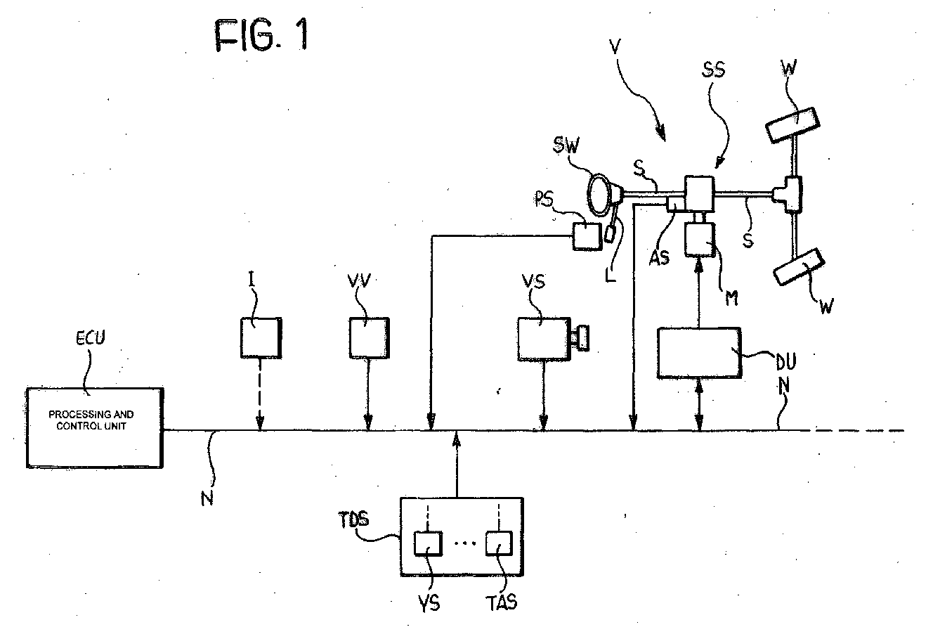
- a motor vehicle V includes in a manner known per se a pair of steerable wheels W associated with a steering column S which can be controlled by a steering wheel SW.
- an electrically controlled servo-steering assembly SS is associated with the steering column S, including for example an electric operating motor M as well as sensor devices AS operable to supply electrical signals indicating the steering angle and the couple that the driver is applying to the steering column S.
- the motor vehicle V has direction indicator devices which can be activated selectively, for example by means of a manually operable lever L, so as to warn of a change of direction.
- the motor vehicle V is fitted with a driving assistance system of the invention which includes a vision system VS operable to supply electrical signals which can be used to identify the instantaneous position of the vehicle V in relation to detectable lines of demarcation which limit laterally or define a lane in which the vehicle is travelling along a road.
- this vision system could include a video-camera directed at the road ahead of the motor vehicle, in association with hardware for processing the image signals generated by the camera.
- the driving assistance system also includes a sensor device PS, associated with the control member L for controlling the direction indicators, to provide electric signals indicating whether these indicators are activated or not.
- the driving assistance system further includes a sensor VV operable to supply electrical signals indicating the speed at which the vehicle is travelling. This sensor can be shared with other control systems installed in the vehicle.
- An electronic processing and control unit is connected to the sensor AS associated with the steering column S, to the sensor PS associated with the direction indicator control member, to the vision system VS and to the sensor VV for sensing the speed of the vehicle.
- the processing and control unit ECU can, for example, be connected to the said sensors by a communication network N installed in the vehicle, such as a network operating under the CAN protocol, for example.
- Sensors/transducers of a system for measuring the transverse dynamics of the motor vehicle are also connected to the processing and control unit ECU by means of the network N.
- This system includes, for example, a sensor YS operable to supply electrical signals indicating the yaw speed of the vehicle, as well as a sensor TAS operable to provide electrical signals indicating the transverse acceleration thereof.
- the unit ECU is also connected to a driving unit DU associated with the motor M of the servo-steering assembly SS.
- the processing and control unit ECU is operable, by means of the driving unit DU, to control the servo-steering assembly SS in such a way as to apply a resistant couple of a predetermined value to the steering column S when the signals emitted by the vision system VS and the sensor PS indicate that the vehicle V is about to leave the lane in which it is travelling and the direction indicators are not activated.
- the function carried out by the driving assistance system is deactivated on the other hand, although turned on ready for use, if the driver selectively activates an indicator with a view to deliberately changing lane.
- the processing and control unit ECU is preferably operable to calculate the radius of curvature of the portion of road on which the vehicle V is travelling. This operation is easily carried out using signals emitted by the vision system VS. On the basis of this information, the unit ECU is able to calculate the resistant couple to be applied to the steering column S according to different methods, in dependence on whether the portion of road along which the vehicle V is travelling is essentially straight or curved.
- the unit ECU can also be set not only to analyze the signals emitted by the vision system VS but also, in the case of a road with a plurality of contiguous lanes, to recognize in which one the vehicle is travelling.
- the resistant couple which would need to be applied to the steering column S is calculated according to a variety of methods, depending on which lane the vehicle is travelling in (middle lane, left hand lane or right hand lane, for example).
- the resistant couple which would need to be applied to the steering column S is preferably calculated as a function of the instantaneous transverse position of the vehicle V within the lane along which the vehicle is travelling.
- the resistant couple to be applied to the steering column S is calculated as a function of the value of the couple which the driver is applying to the steering column S.
- An additional parameter which the processing unit ECU might take into account when calculating the resistant couple to be applied to the steering column is the camber of the portion of road along which the vehicle is moving. This camber can be worked out on the basis of image signals provided by the vision system VS, or by means of a special inclinometric sensor, such as that indicated I in Figure 1.
- the flow chart of Figure 2 shows, in a manner requiring no further explanation, the logical sequence of the main operations carried out by the driving assistance system outlined above.
- the driving assistance system first of all checks whether the driver is intending to change lane or, more generally, to move out of the lane in which the vehicle is. It does this by checking whether the direction indicators have been activated or not.
- the driving assistance system calculates that it needs to intervene, it will adopt a different control strategy in dependence on whether the vehicle is moving along a straight stretch of road or a curved one. If the portion of road includes a plurality of driving lanes, the system determines in which one the vehicle is travelling and then works out the couple to be applied to the steering column in accordance with this information.
- the resistant couple exerted by the system is calculated in dependence on the other parameters or values mentioned earlier.
Landscapes
- Engineering & Computer Science (AREA)
- Chemical & Material Sciences (AREA)
- Combustion & Propulsion (AREA)
- Transportation (AREA)
- Mechanical Engineering (AREA)
- Steering Control In Accordance With Driving Conditions (AREA)
- Control Of Multiple Motors (AREA)
- Arrangement Or Mounting Of Propulsion Units For Vehicles (AREA)
- Control Of Throttle Valves Provided In The Intake System Or In The Exhaust System (AREA)
- Hydraulic Clutches, Magnetic Clutches, Fluid Clutches, And Fluid Joints (AREA)
- Transition And Organic Metals Composition Catalysts For Addition Polymerization (AREA)
- Control Of Position, Course, Altitude, Or Attitude Of Moving Bodies (AREA)
- Traffic Control Systems (AREA)
Abstract
Description
detector means operable to emit electric signals which can be used to identify the instantaneous position of a vehicle relative to detectable demarcation means delimiting or defining a lane of the road on which the vehicle is travelling;
sensor means for detecting activations of the direction indicators, and
electronic processing and control means, connected to the said detector means and to the said sensor means and operable to control the said steering actuator means so as to cause a resistant couple of a predetermined value to be applied to the driving wheel, when the signals supplied by the said detector means and the sensor means indicate that the motor vehicle is about to leave the said lane and the direction indicators are not activated.
Claims (8)
- A driving assistance system for a motor vehicle (V) with electrically controlled steering actuator means (SS) and selectively operable direction indicators for warning of a change of direction; the system comprising
detector means (VS) operable to provide electrical signals which can be used to identify the instantaneous position of the motor vehicle (V) relative to detectable demarcation means which mark out or define a lane of a road along which the vehicle is travelling,
sensor means (PS) indicating whether the direction indicators of the vehicle are activated,
electronic processing and control means (ECU) connected to the said detector means (VS) and the said sensor means (PS) and operable to control the said steering actuator means (SS) in such a way as to cause a resistant couple of a predetermined value to be applied to the steering column (S) in the event of signals provided by the said detector means (VS) and sensor means (PS) indicating that the motor vehicle (V) is about to leave the said lane of the road on which it is moving and the direction indicators are found not to be activated. - A system according to Claim 1, in which the said processing and control means (ECU) are operable to calculate the radius of curvature of the stretch of road along which the vehicle (V) is moving and to calculate the resistant couple to be applied to the steering column (S) according to different methods in dependence on whether the stretch of road on which the vehicle (V) is moving is essentially straight or curved.
- A system according to Claim 2, in which the said processing and control means (ECU) are operable to analyze signals provided by the said detector means (VS) and, in the event of the road on which the vehicle (V) is travelling having a plurality of contiguous lanes, being able to determine in which lane the vehicle is travelling and to calculate a resistant couple of a value which is variable as a function of the lane on which the vehicle (V) is travelling and apply this to the steering column (S).
- A system according to any preceding Claim, in which the said processing and control means (ECU) are operable to calculate the said resistant couple value in dependence on the transverse position of the motor vehicle (V) within the lane along which it is travelling.
- A system according to any preceding Claim, which also includes additional detector means (VV; YS; TAS) operable to supply signals indicating at least one parameter of a group of parameters which includes the speed at which the vehicle (V) is moving, the yaw speed and the transverse acceleration of the motor vehicle (V) and in which the said electronic processing and control means (ECU) are operable to calculate the value of the aforesaid resistant couple which might have to be applied to the steering column (S) in dependence on the value of the said at least one parameter.
- A system according to any preceding Claim, which also includes additional sensor means (AS) operable to supply electrical signals indicating the couple applied by the driver to the steering column (S), and in which the said electronic processing and control means (ECU) are operable to calculate the value of the said resistant couple also in dependence on the value of the couple applied to the steering column by (S) by the driver.
- A system according to any preceding Claim, in which the said processing and control means (ECU) are operable to calculate the value of the said resistant couple in dependence on the camber of the portion of road along which the motor vehicle (V) is moving.
- A system according to any preceding Claim, in which the said detector means include a vision system (VS) comprising a video camera or the like.
Applications Claiming Priority (2)
| Application Number | Priority Date | Filing Date | Title |
|---|---|---|---|
| IT2002TO000129A ITTO20020129A1 (en) | 2002-02-15 | 2002-02-15 | VEHICLE DRIVING AID SYSTEM. |
| ITTO20020129 | 2002-07-05 |
Publications (3)
| Publication Number | Publication Date |
|---|---|
| EP1336550A2 true EP1336550A2 (en) | 2003-08-20 |
| EP1336550A3 EP1336550A3 (en) | 2004-03-31 |
| EP1336550B1 EP1336550B1 (en) | 2010-08-04 |
Family
ID=27621208
Family Applications (1)
| Application Number | Title | Priority Date | Filing Date |
|---|---|---|---|
| EP03002957A Expired - Lifetime EP1336550B1 (en) | 2002-02-15 | 2003-02-11 | A driving assistance system for a motor vehicle |
Country Status (4)
| Country | Link |
|---|---|
| EP (1) | EP1336550B1 (en) |
| AT (1) | ATE476349T1 (en) |
| DE (1) | DE60333610D1 (en) |
| IT (1) | ITTO20020129A1 (en) |
Cited By (2)
| Publication number | Priority date | Publication date | Assignee | Title |
|---|---|---|---|---|
| EP1726513A1 (en) | 2005-05-02 | 2006-11-29 | Iveco S.p.A. | Driving assistance system for lane keeping support, for lane change assistance, and for driver status monitoring for a vehicle |
| WO2018127430A1 (en) * | 2017-01-04 | 2018-07-12 | Robert Bosch Gmbh | Reducing lateral position deviation during an automated lane change |
Family Cites Families (1)
| Publication number | Priority date | Publication date | Assignee | Title |
|---|---|---|---|---|
| JP3599144B2 (en) * | 1996-05-09 | 2004-12-08 | 本田技研工業株式会社 | Vehicle steering assist system |
-
2002
- 2002-02-15 IT IT2002TO000129A patent/ITTO20020129A1/en unknown
-
2003
- 2003-02-11 DE DE60333610T patent/DE60333610D1/en not_active Expired - Lifetime
- 2003-02-11 EP EP03002957A patent/EP1336550B1/en not_active Expired - Lifetime
- 2003-02-11 AT AT03002957T patent/ATE476349T1/en not_active IP Right Cessation
Cited By (4)
| Publication number | Priority date | Publication date | Assignee | Title |
|---|---|---|---|---|
| EP1726513A1 (en) | 2005-05-02 | 2006-11-29 | Iveco S.p.A. | Driving assistance system for lane keeping support, for lane change assistance, and for driver status monitoring for a vehicle |
| WO2018127430A1 (en) * | 2017-01-04 | 2018-07-12 | Robert Bosch Gmbh | Reducing lateral position deviation during an automated lane change |
| US10150474B2 (en) | 2017-01-04 | 2018-12-11 | Robert Bosch Gmbh | Reducing lateral position deviation during an automated lane change |
| JP2020506837A (en) * | 2017-01-04 | 2020-03-05 | ローベルト ボツシユ ゲゼルシヤフト ミツト ベシユレンクテル ハフツングRobert Bosch Gmbh | Reduction of lateral position deviation while changing lanes |
Also Published As
| Publication number | Publication date |
|---|---|
| ATE476349T1 (en) | 2010-08-15 |
| DE60333610D1 (en) | 2010-09-16 |
| EP1336550B1 (en) | 2010-08-04 |
| EP1336550A3 (en) | 2004-03-31 |
| ITTO20020129A1 (en) | 2003-08-18 |
| ITTO20020129A0 (en) | 2002-02-15 |
Similar Documents
| Publication | Publication Date | Title |
|---|---|---|
| US11753007B2 (en) | Vehicular lane centering system | |
| US9751561B2 (en) | Differential control user interface for reversing vehicle and trailer system | |
| RU2412848C2 (en) | System to aid driving in parking and method of its operation | |
| EP1726513B1 (en) | Driving assistance system for lane keeping support, for lane change assistance, and for driver status monitoring for a vehicle | |
| KR101320223B1 (en) | Method and system for assisting a driver when parking or manoeuvring a motor vehicle | |
| JP4543599B2 (en) | Automatic vehicle evacuation device | |
| US8583341B2 (en) | Method for the open-loop and closed-loop control of traffic flow | |
| JP5737197B2 (en) | Vehicle trajectory control device | |
| US20050004731A1 (en) | Drive-assist system | |
| US20070179697A1 (en) | Lane departure warning system and method | |
| US20230041499A1 (en) | Method for determining the current angle of lateral inclination of a roadway | |
| JP4792289B2 (en) | Vehicle travel control device | |
| EP3078559B1 (en) | Enhancing motor vehicle driver awareness of motor vehicle degree of proximity to a motor vehicle roadholding limit during sports driving | |
| EP1336550B1 (en) | A driving assistance system for a motor vehicle | |
| DE102006060456B4 (en) | Method and system for steering a vehicle into a parking space | |
| CN109733354B (en) | Vehicle and curve auxiliary control method thereof | |
| CN117622127A (en) | lane departure prevention device | |
| JP2024051387A (en) | Vehicle control apparatus | |
| JP2023122298A (en) | Driving support device | |
| GB2615203A (en) | Vehicle control system and method | |
| KR20010059066A (en) | A system for getting curvature data of a road using a radar |
Legal Events
| Date | Code | Title | Description |
|---|---|---|---|
| PUAI | Public reference made under article 153(3) epc to a published international application that has entered the european phase |
Free format text: ORIGINAL CODE: 0009012 |
|
| AK | Designated contracting states |
Designated state(s): AT BE BG CH CY CZ DE DK EE ES FI FR GB GR HU IE IT LI LU MC NL PT SE SI SK TR |
|
| AX | Request for extension of the european patent |
Extension state: AL LT LV MK RO |
|
| PUAL | Search report despatched |
Free format text: ORIGINAL CODE: 0009013 |
|
| AK | Designated contracting states |
Kind code of ref document: A3 Designated state(s): AT BE BG CH CY CZ DE DK EE ES FI FR GB GR HU IE IT LI LU MC NL PT SE SI SK TR |
|
| AX | Request for extension of the european patent |
Extension state: AL LT LV MK RO |
|
| 17P | Request for examination filed |
Effective date: 20040916 |
|
| AKX | Designation fees paid |
Designated state(s): AT BE BG CH CY CZ DE DK EE ES FI FR GB GR HU IE IT LI LU MC NL PT SE SI SK TR |
|
| 17Q | First examination report despatched |
Effective date: 20070131 |
|
| GRAP | Despatch of communication of intention to grant a patent |
Free format text: ORIGINAL CODE: EPIDOSNIGR1 |
|
| GRAS | Grant fee paid |
Free format text: ORIGINAL CODE: EPIDOSNIGR3 |
|
| GRAA | (expected) grant |
Free format text: ORIGINAL CODE: 0009210 |
|
| AK | Designated contracting states |
Kind code of ref document: B1 Designated state(s): AT BE BG CH CY CZ DE DK EE ES FI FR GB GR HU IE IT LI LU MC NL PT SE SI SK TR |
|
| REG | Reference to a national code |
Ref country code: GB Ref legal event code: FG4D |
|
| REG | Reference to a national code |
Ref country code: CH Ref legal event code: EP |
|
| REG | Reference to a national code |
Ref country code: IE Ref legal event code: FG4D |
|
| REF | Corresponds to: |
Ref document number: 60333610 Country of ref document: DE Date of ref document: 20100916 Kind code of ref document: P |
|
| REG | Reference to a national code |
Ref country code: NL Ref legal event code: VDEP Effective date: 20100804 |
|
| PG25 | Lapsed in a contracting state [announced via postgrant information from national office to epo] |
Ref country code: AT Free format text: LAPSE BECAUSE OF FAILURE TO SUBMIT A TRANSLATION OF THE DESCRIPTION OR TO PAY THE FEE WITHIN THE PRESCRIBED TIME-LIMIT Effective date: 20100804 Ref country code: NL Free format text: LAPSE BECAUSE OF FAILURE TO SUBMIT A TRANSLATION OF THE DESCRIPTION OR TO PAY THE FEE WITHIN THE PRESCRIBED TIME-LIMIT Effective date: 20100804 Ref country code: FI Free format text: LAPSE BECAUSE OF FAILURE TO SUBMIT A TRANSLATION OF THE DESCRIPTION OR TO PAY THE FEE WITHIN THE PRESCRIBED TIME-LIMIT Effective date: 20100804 |
|
| PG25 | Lapsed in a contracting state [announced via postgrant information from national office to epo] |
Ref country code: CY Free format text: LAPSE BECAUSE OF FAILURE TO SUBMIT A TRANSLATION OF THE DESCRIPTION OR TO PAY THE FEE WITHIN THE PRESCRIBED TIME-LIMIT Effective date: 20100804 Ref country code: BG Free format text: LAPSE BECAUSE OF FAILURE TO SUBMIT A TRANSLATION OF THE DESCRIPTION OR TO PAY THE FEE WITHIN THE PRESCRIBED TIME-LIMIT Effective date: 20101104 Ref country code: PT Free format text: LAPSE BECAUSE OF FAILURE TO SUBMIT A TRANSLATION OF THE DESCRIPTION OR TO PAY THE FEE WITHIN THE PRESCRIBED TIME-LIMIT Effective date: 20101206 Ref country code: SI Free format text: LAPSE BECAUSE OF FAILURE TO SUBMIT A TRANSLATION OF THE DESCRIPTION OR TO PAY THE FEE WITHIN THE PRESCRIBED TIME-LIMIT Effective date: 20100804 |
|
| PG25 | Lapsed in a contracting state [announced via postgrant information from national office to epo] |
Ref country code: SE Free format text: LAPSE BECAUSE OF FAILURE TO SUBMIT A TRANSLATION OF THE DESCRIPTION OR TO PAY THE FEE WITHIN THE PRESCRIBED TIME-LIMIT Effective date: 20100804 Ref country code: BE Free format text: LAPSE BECAUSE OF FAILURE TO SUBMIT A TRANSLATION OF THE DESCRIPTION OR TO PAY THE FEE WITHIN THE PRESCRIBED TIME-LIMIT Effective date: 20100804 Ref country code: GR Free format text: LAPSE BECAUSE OF FAILURE TO SUBMIT A TRANSLATION OF THE DESCRIPTION OR TO PAY THE FEE WITHIN THE PRESCRIBED TIME-LIMIT Effective date: 20101105 |
|
| PG25 | Lapsed in a contracting state [announced via postgrant information from national office to epo] |
Ref country code: DK Free format text: LAPSE BECAUSE OF FAILURE TO SUBMIT A TRANSLATION OF THE DESCRIPTION OR TO PAY THE FEE WITHIN THE PRESCRIBED TIME-LIMIT Effective date: 20100804 |
|
| PG25 | Lapsed in a contracting state [announced via postgrant information from national office to epo] |
Ref country code: SK Free format text: LAPSE BECAUSE OF FAILURE TO SUBMIT A TRANSLATION OF THE DESCRIPTION OR TO PAY THE FEE WITHIN THE PRESCRIBED TIME-LIMIT Effective date: 20100804 Ref country code: CZ Free format text: LAPSE BECAUSE OF FAILURE TO SUBMIT A TRANSLATION OF THE DESCRIPTION OR TO PAY THE FEE WITHIN THE PRESCRIBED TIME-LIMIT Effective date: 20100804 Ref country code: EE Free format text: LAPSE BECAUSE OF FAILURE TO SUBMIT A TRANSLATION OF THE DESCRIPTION OR TO PAY THE FEE WITHIN THE PRESCRIBED TIME-LIMIT Effective date: 20100804 |
|
| PLBE | No opposition filed within time limit |
Free format text: ORIGINAL CODE: 0009261 |
|
| STAA | Information on the status of an ep patent application or granted ep patent |
Free format text: STATUS: NO OPPOSITION FILED WITHIN TIME LIMIT |
|
| PG25 | Lapsed in a contracting state [announced via postgrant information from national office to epo] |
Ref country code: ES Free format text: LAPSE BECAUSE OF FAILURE TO SUBMIT A TRANSLATION OF THE DESCRIPTION OR TO PAY THE FEE WITHIN THE PRESCRIBED TIME-LIMIT Effective date: 20101115 |
|
| 26N | No opposition filed |
Effective date: 20110506 |
|
| REG | Reference to a national code |
Ref country code: DE Ref legal event code: R097 Ref document number: 60333610 Country of ref document: DE Effective date: 20110506 |
|
| PG25 | Lapsed in a contracting state [announced via postgrant information from national office to epo] |
Ref country code: MC Free format text: LAPSE BECAUSE OF NON-PAYMENT OF DUE FEES Effective date: 20110228 |
|
| REG | Reference to a national code |
Ref country code: CH Ref legal event code: PL |
|
| GBPC | Gb: european patent ceased through non-payment of renewal fee |
Effective date: 20110211 |
|
| PG25 | Lapsed in a contracting state [announced via postgrant information from national office to epo] |
Ref country code: LI Free format text: LAPSE BECAUSE OF NON-PAYMENT OF DUE FEES Effective date: 20110228 Ref country code: CH Free format text: LAPSE BECAUSE OF NON-PAYMENT OF DUE FEES Effective date: 20110228 |
|
| REG | Reference to a national code |
Ref country code: IE Ref legal event code: MM4A |
|
| PG25 | Lapsed in a contracting state [announced via postgrant information from national office to epo] |
Ref country code: IE Free format text: LAPSE BECAUSE OF NON-PAYMENT OF DUE FEES Effective date: 20110211 |
|
| PG25 | Lapsed in a contracting state [announced via postgrant information from national office to epo] |
Ref country code: GB Free format text: LAPSE BECAUSE OF NON-PAYMENT OF DUE FEES Effective date: 20110211 |
|
| PG25 | Lapsed in a contracting state [announced via postgrant information from national office to epo] |
Ref country code: LU Free format text: LAPSE BECAUSE OF NON-PAYMENT OF DUE FEES Effective date: 20110211 |
|
| PG25 | Lapsed in a contracting state [announced via postgrant information from national office to epo] |
Ref country code: TR Free format text: LAPSE BECAUSE OF FAILURE TO SUBMIT A TRANSLATION OF THE DESCRIPTION OR TO PAY THE FEE WITHIN THE PRESCRIBED TIME-LIMIT Effective date: 20100804 |
|
| PG25 | Lapsed in a contracting state [announced via postgrant information from national office to epo] |
Ref country code: HU Free format text: LAPSE BECAUSE OF FAILURE TO SUBMIT A TRANSLATION OF THE DESCRIPTION OR TO PAY THE FEE WITHIN THE PRESCRIBED TIME-LIMIT Effective date: 20100804 |
|
| REG | Reference to a national code |
Ref country code: FR Ref legal event code: PLFP Year of fee payment: 14 |
|
| REG | Reference to a national code |
Ref country code: FR Ref legal event code: PLFP Year of fee payment: 15 |
|
| REG | Reference to a national code |
Ref country code: FR Ref legal event code: PLFP Year of fee payment: 16 |
|
| PGFP | Annual fee paid to national office [announced via postgrant information from national office to epo] |
Ref country code: DE Payment date: 20220217 Year of fee payment: 20 |
|
| PGFP | Annual fee paid to national office [announced via postgrant information from national office to epo] |
Ref country code: IT Payment date: 20220207 Year of fee payment: 20 Ref country code: FR Payment date: 20220228 Year of fee payment: 20 |
|
| REG | Reference to a national code |
Ref country code: DE Ref legal event code: R071 Ref document number: 60333610 Country of ref document: DE |