EP1336371A1 - Model eye for eye characteristic measuring device and calibration method for the same - Google Patents
Model eye for eye characteristic measuring device and calibration method for the same Download PDFInfo
- Publication number
- EP1336371A1 EP1336371A1 EP03090041A EP03090041A EP1336371A1 EP 1336371 A1 EP1336371 A1 EP 1336371A1 EP 03090041 A EP03090041 A EP 03090041A EP 03090041 A EP03090041 A EP 03090041A EP 1336371 A1 EP1336371 A1 EP 1336371A1
- Authority
- EP
- European Patent Office
- Prior art keywords
- eye
- lens
- model
- measuring device
- anterior
- Prior art date
- Legal status (The legal status is an assumption and is not a legal conclusion. Google has not performed a legal analysis and makes no representation as to the accuracy of the status listed.)
- Granted
Links
- 238000000034 method Methods 0.000 title claims abstract description 23
- 230000004075 alteration Effects 0.000 claims abstract description 97
- 238000009792 diffusion process Methods 0.000 claims abstract description 51
- 238000005259 measurement Methods 0.000 claims abstract description 14
- 238000010276 construction Methods 0.000 claims description 39
- 230000003287 optical effect Effects 0.000 claims description 23
- 210000004087 cornea Anatomy 0.000 claims description 8
- 230000036040 emmetropia Effects 0.000 claims 2
- 238000004519 manufacturing process Methods 0.000 description 6
- 238000012986 modification Methods 0.000 description 5
- 230000004048 modification Effects 0.000 description 5
- 210000001747 pupil Anatomy 0.000 description 4
- 201000009310 astigmatism Diseases 0.000 description 3
- 230000015572 biosynthetic process Effects 0.000 description 3
- 239000002184 metal Substances 0.000 description 2
- 230000007935 neutral effect Effects 0.000 description 2
- 238000002360 preparation method Methods 0.000 description 2
- 206010020675 Hypermetropia Diseases 0.000 description 1
- 230000003247 decreasing effect Effects 0.000 description 1
- 239000011521 glass Substances 0.000 description 1
- 201000006318 hyperopia Diseases 0.000 description 1
- 230000004305 hyperopia Effects 0.000 description 1
- 208000001491 myopia Diseases 0.000 description 1
- 230000004379 myopia Effects 0.000 description 1
- 210000001525 retina Anatomy 0.000 description 1
Images



Classifications
-
- A—HUMAN NECESSITIES
- A61—MEDICAL OR VETERINARY SCIENCE; HYGIENE
- A61B—DIAGNOSIS; SURGERY; IDENTIFICATION
- A61B3/00—Apparatus for testing the eyes; Instruments for examining the eyes
- A61B3/10—Objective types, i.e. instruments for examining the eyes independent of the patients' perceptions or reactions
- A61B3/1015—Objective types, i.e. instruments for examining the eyes independent of the patients' perceptions or reactions for wavefront analysis
-
- A—HUMAN NECESSITIES
- A61—MEDICAL OR VETERINARY SCIENCE; HYGIENE
- A61B—DIAGNOSIS; SURGERY; IDENTIFICATION
- A61B3/00—Apparatus for testing the eyes; Instruments for examining the eyes
-
- A—HUMAN NECESSITIES
- A61—MEDICAL OR VETERINARY SCIENCE; HYGIENE
- A61B—DIAGNOSIS; SURGERY; IDENTIFICATION
- A61B3/00—Apparatus for testing the eyes; Instruments for examining the eyes
- A61B3/0016—Operational features thereof
- A61B3/0025—Operational features thereof characterised by electronic signal processing, e.g. eye models
-
- G—PHYSICS
- G09—EDUCATION; CRYPTOGRAPHY; DISPLAY; ADVERTISING; SEALS
- G09B—EDUCATIONAL OR DEMONSTRATION APPLIANCES; APPLIANCES FOR TEACHING, OR COMMUNICATING WITH, THE BLIND, DEAF OR MUTE; MODELS; PLANETARIA; GLOBES; MAPS; DIAGRAMS
- G09B23/00—Models for scientific, medical, or mathematical purposes, e.g. full-sized devices for demonstration purposes
- G09B23/28—Models for scientific, medical, or mathematical purposes, e.g. full-sized devices for demonstration purposes for medicine
- G09B23/30—Anatomical models
- G09B23/32—Anatomical models with moving parts
-
- A—HUMAN NECESSITIES
- A61—MEDICAL OR VETERINARY SCIENCE; HYGIENE
- A61B—DIAGNOSIS; SURGERY; IDENTIFICATION
- A61B2560/00—Constructional details of operational features of apparatus; Accessories for medical measuring apparatus
- A61B2560/02—Operational features
- A61B2560/0223—Operational features of calibration, e.g. protocols for calibrating sensors
- A61B2560/0228—Operational features of calibration, e.g. protocols for calibrating sensors using calibration standards
- A61B2560/0233—Optical standards
Definitions
- the present invention relates to a model eye for an eye characteristic measuring device and a calibration method for the model eye, and more particularly, to a model eye for an eye characteristic measuring device for confirming the measurement accuracy of a wave aberration measuring device for a subject eye as well as to a calibration method for the model eye.
- an object of the invention is to provide a model eye for an eye characteristic measuring device and a calibration method for the model eye.
- the model eye can have various aberrations and/or power characteristics to be formed by a combination of a refractive-type lens for use in the related model eye and a phase plate for adding aberration and can be used to confirm the accuracy of wavefront measurement or the like of the eye characteristic measuring device.
- Another object of the invention is to provide a model eye for an eye characteristic measuring device and a calibration method for the model eye.
- the model eye is constructed so that a thin light beam is made incident on the model eye and the incident light beam is made to exit from the model eye as a reflected light beam which has a predetermined diameter larger than the diameter of the incident light beam and contains a predetermined higher order aberration.
- a model eye for an eye characteristic measuring device which includes:
- a calibration method for a model eye for an eye characteristic measuring device comprising an anterior eye lens forming a predetermined power to be given to the model eye, a diffusion surface diffusing and reflecting incident light, the diffusion surface being disposed at an image point position corresponding to the predetermined power in relationship to the anterior eye lens, and a phase plate giving a predetermined aberration to an area between the anterior eye lens and the diffusion surface, and power and aberration required for the model eye being formed by the anterior eye lens and the phase plate
- the calibration method including:
- Figs. 1A, 1B and 1C are views showing the construction of a first embodiment of the model eye for an eye characteristic measuring device according to the invention.
- Fig. 1A is a front view
- Fig. 1B is a side view
- Fig. 1C is a plane view.
- Fig. 2 is a cross-sectional view of the first embodiment of the model eye for the eye characteristic measuring device according to the invention.
- Fig. 3 is a view showing the construction of a phase plate.
- the shown model eye includes an anterior eye lens 1, a diffusion surface 2, an aberration adding member 3 and a housing 5.
- the anterior eye lens 1 forms a predetermined power to be given to the model eye.
- the front surface of the anterior eye lens 1 corresponds to the front surface of the cornea of an eye, and can be made to approximate a general radius of curvature of the front surface of the cornea (for example, 7.5 mm).
- the aberration adding member 3 can also be constructed to cancel this residual aberration and give a predetermined aberration.
- the anterior eye lens 1 is preferably formed of a lens having as small aberrations as possible, such as a combination of a plurality of lens elements and/or a cemented lens. Accordingly, even if conditions are modified, the anterior eye lens 1 can be designed so that variations in the influence of aberration due to the anterior eye lens 1 become as small as possible.
- the diffusion surface 2 randomly diffuses and reflects incident light (for example, its reflectance may be made 10% or less, but is not limited to this numerical example).
- the diffusion surface 2 is disposed at an image point position (approximately at an image plane position) which corresponds to the predetermined power in relationship to the anterior eye lens 1 when the aberration adding member 3 is inserted.
- the diffusion surface 2 may also be disposed approximately at the focal length position of the anterior eye lens 1 that is determined when the aberration adding member 3 is inserted.
- the reflectance of the diffusion surface 2 may also be set to become sufficiently large with respect to the level of noise light such as reflected light from the aberration adding member 3.
- the aberration adding member 3 gives the predetermined aberration to an area between the anterior eye lens 1 and the diffusion surface 2.
- the aberration adding member 3 adds the predetermined aberration by means of a phase plate 31 to an area which allows the amount of aberration to be detected in a diameter corresponding to a diameter to be measured on a pupil, and the influence of light coming from the outside of the diameter is eliminated by a light limiting portion 32 disposed around the phase plate 31.
- the phase plate 31 may use a binary optics element (BOE). It is appropriate that the position of the phase plate 31 coincide with the pupil position of the eye, but the position of the phase plate 31 may also be deviated to a small extent or disposed before the anterior eye lens 1 (refer to Fig. 11 which will be mentioned later).
- BOE binary optics element
- the housing 5 covers a portion of the anterior eye lens 1, the phase plate 31 and the diffusion surface 2. Accordingly, the housing 5 is constructed to prevent foreign matter from adhering to the diffusion surface 2 and the phase plate 31. In addition, the housing 5 may also have graduations formed on the periphery of its metal part so that the angle of rotation of the model eye can be detected.
- Fig. 4 is a view showing the construction of a second embodiment of the model eye for an eye characteristic measuring device.
- the aberration adding member 3 is disposed to be tilted at a predetermined (small) angle with respect to the optical axis as shown in Fig. 4 so that the influence of reflection from the aberration adding member 3 is restrained.
- the phase plate 31 such as a binary optics element (BOE) is formed to take the tilt and the like into account.
- BOE binary optics element
- Fig. 5 is a view showing the construction of a third embodiment of the model eye for an eye characteristic measuring device.
- the third embodiment is intended for cases such as the case of increasing the reflectance of the diffusion surface 2 which corresponds to a fundus.
- a neutral density (ND) filter 4 or the like is disposed before the aberration adding member 3 so that the total amount of reflected light can be decreased to reduce the ratio of the amount of reflected noise light to the amount of light reflected from the fundus.
- the neutral density filter 4 may also be disposed before the anterior eye lens 1.
- Fig. 11 is a view showing the construction of a fourth embodiment of the model eye for an eye characteristic measuring device.
- the aberration adding member 3 is disposed before the anterior eye lens 1.
- Power and aberration to be given to the model eye can be formed by two kinds of methods as will be described below by way of example.
- the diameter of a light beam to be given to the phase plate 31 is determined from the relationship between the diameter of a light beam exiting from the model eye and the diameter of a light beam passing through the phase plate 31.
- Fig. 6 is a view (1) showing the values of the Zernike polynomial.
- r coordinate may be converted to x, y coordinates.
- Fig. 7 is a view (2) showing the values of the Zernike circle polynomial for this case.
- Fig. 8 is a view showing the construction of a calibration device for the model eye for an eye characteristic measuring device.
- the shown calibration device includes an interferometer 11, a pinhole plate 12 and a reference mirror 13.
- the diffusion surface 2 is constructed to be removably attached to the model eye
- the pinhole plate 12 having a pinhole formed in a fundus portion is attached to the model eye in place of the diffusion surface 2 and is subjected to alignment, and the optical characteristics (optical aberrations) of the model eye are measured with the interferometer 11.
- the optical characteristics of the model eye are estimated from the measured result, and the pinhole plate 12 is replaced with the diffusion surface 2, thus preparing the model eye.
- the positional relationship between the interferometer 11 and the model eye is adjusted so that light converges at the pinhole position of the pinhole plate 12 disposed in place of the diffusion surface 2 with respect to the anterior eye lens 1 and the aberration adding member 3 of the model eye.
- the pinhole of the model eye is disposed to approximately coincide with the center of curvature of the reference mirror 13.
- the pinhole plate 12 and the reference mirror 13 are arranged in accordance with the above-described preparation for measurement, a light beam emitted from the interferometer 11 converges at a position conjugated with the pinhole with respect to the anterior eye lens 1 and the phase plate 31, and the light beam again converges at the position of the pinhole so that the light beam passes through the pinhole. Then, the light beam which has passed through the pinhole is reflected by the reference mirror 13, and again passes through the pinhole and returns to the interferometer 11 as a measurement light beam.
- the interferometer 11 causes the measurement light beam and the reference light beam reflected from the reference mirror 13 to interfere with each other by means of a beam splitter or the like, and measures the aberration amount and the optical characteristics of the entire model eye from the obtained interference fringes.
- a model eye can be constructed so that at least one characteristic element selected from among the refractive power, the astigmatism and the astigmatism axis of the model eye can be modified, by means of any one of constructions which will be described below by way of example or by means of a combination of any ones of the constructions.
- the anterior eye lens 1 is made of a zoom lens system so that the focal length of the anterior eye lens 1 can be modified, and some lenses of the zoom lens system are moved in the direction of the optical axis to modify the entire focal length, thereby modifying the power of the anterior eye lens 1.
- a construction in which a cylindrical lens component such as a cylindrical lens can be added and modified.
- the anterior eye lens 1 is preferably formed of a lens such as a combination of a plurality of lens elements and/or a cemented lens so that the model eye is designed so that even if conditions are modified, variations in the influence of aberration due to the anterior eye lens 1 become as small as possible.
- a lens of a symmetrical type such as a Gaussian type, an aspherical lens, a group of lenses using glasses having a rich variety of refractive indices, or a triplet.
- model eyes having various degrees of refractive power, various degrees of astigmatic power or various aberrations will be described below.
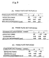
- Figs. 9A to 9C are explanatory views of design and manufacture examples of various model eyes.
- Fig. 9A shows the case where only the diffusion surface 2 is moved without the replacement of the aberration adding member 3 (the phase plate 31).
- Fig. 9B shows the case where only the anterior eye lens 1 is moved without the replacement of the aberration adding member 3 (the phase plate 31).
- Fig. 9C shows the case where the aberration adding member 3 (the phase plate 31) is replaced or moved and only the diffusion surface 2 is moved.
- the aberration adding member 3 the phase plate 31
- the aberration adding member 3 (the phase plate 31) is not replaced or moved and both the anterior eye lens 1 and the diffusion surface 2 are moved, or in which the aberration adding member 3 (the phase plate 31) is replaced or moved and both the anterior eye lens 1 and the diffusion surface 2 are also moved.
- Fig. 10 is a view showing the construction of a fifth embodiment of the model eye for an eye characteristic measuring device.
- the front surface of the anterior eye lens 1 is made of, for example, a spherical surface, an aspherical surface and a toric surface, and the radius of curvature of the front surface can be made to approximate a general radius of curvature of the front surface of the cornea (for example, 7.5 mm).
- the fifth embodiment makes it possible to measure various corneal shapes.
- the shape of the front surface of the anterior eye lens exchanging member 5 is made conical, it is possible to measure the shape of the cornea with a light beam having an angle, whereby it is possible to realize more accurate measurement.
- the model eye of the fifth embodiment can be used to perform calibrating measurement at the same time.
- the anterior eye lens exchanging member 5 alone can also be used as a model eye for calibrating only the corneal shape.
- the diffusion surface 2 can also be constructed to be finely vibrated in directions perpendicular to the optical axis or to rotate about an axis parallel to the optical axis. This construction has the advantage that nonuniform reflection at the diffusion surface 2 can be eliminated.
Landscapes
- Health & Medical Sciences (AREA)
- Life Sciences & Earth Sciences (AREA)
- Engineering & Computer Science (AREA)
- Physics & Mathematics (AREA)
- General Health & Medical Sciences (AREA)
- Medical Informatics (AREA)
- Ophthalmology & Optometry (AREA)
- Biomedical Technology (AREA)
- Heart & Thoracic Surgery (AREA)
- Molecular Biology (AREA)
- Surgery (AREA)
- Animal Behavior & Ethology (AREA)
- Biophysics (AREA)
- Public Health (AREA)
- Veterinary Medicine (AREA)
- General Physics & Mathematics (AREA)
- Medicinal Chemistry (AREA)
- Educational Administration (AREA)
- Computational Mathematics (AREA)
- Chemical & Material Sciences (AREA)
- Mathematical Analysis (AREA)
- Mathematical Optimization (AREA)
- Mathematical Physics (AREA)
- Pure & Applied Mathematics (AREA)
- Business, Economics & Management (AREA)
- Algebra (AREA)
- Educational Technology (AREA)
- Theoretical Computer Science (AREA)
- Signal Processing (AREA)
- Eye Examination Apparatus (AREA)
- Instructional Devices (AREA)
- Testing Of Optical Devices Or Fibers (AREA)
- Eyeglasses (AREA)
- Radar Systems Or Details Thereof (AREA)
- Optical Radar Systems And Details Thereof (AREA)
Abstract
Description
- The present invention relates to a model eye for an eye characteristic measuring device and a calibration method for the model eye, and more particularly, to a model eye for an eye characteristic measuring device for confirming the measurement accuracy of a wave aberration measuring device for a subject eye as well as to a calibration method for the model eye.
- In the related model eyes, their anterior eye lenses are made of spherical lenses and the retina are formed by its diffusion surfaces, and their optical characteristics only include refractive power, astigmatic power and spherical aberration. Accordingly, such related model eyes cannot be used for the calibration of eye characteristic measuring devices such as wavefront measurement devices.
- It has recently been desired to provide a model eye capable of generating various wave aberrations and enabling calibration of an eye's optical characteristic measuring device.
- Therefore, an object of the invention is to provide a model eye for an eye characteristic measuring device and a calibration method for the model eye. The model eye can have various aberrations and/or power characteristics to be formed by a combination of a refractive-type lens for use in the related model eye and a phase plate for adding aberration and can be used to confirm the accuracy of wavefront measurement or the like of the eye characteristic measuring device.
- Another object of the invention is to provide a model eye for an eye characteristic measuring device and a calibration method for the model eye. The model eye is constructed so that a thin light beam is made incident on the model eye and the incident light beam is made to exit from the model eye as a reflected light beam which has a predetermined diameter larger than the diameter of the incident light beam and contains a predetermined higher order aberration.
- According to one aspect of the invention, there is provided a model eye for an eye characteristic measuring device which includes:
- an anterior eye lens forming a predetermined power to be given to the model eye;
- a diffusion surface diffusing and reflecting incident light, the diffusion surface being disposed at an image point position corresponding to the predetermined power in relationship to the anterior eye lens; and
- a phase plate giving a predetermined aberration to an area between the anterior eye lens and the diffusion surface,
- wherein power and aberration required for the model eye are formed by the anterior eye lens and the phase plate.
-
- According to another aspect of the invention, there is provided a calibration method for a model eye for an eye characteristic measuring device, the model eye comprising an anterior eye lens forming a predetermined power to be given to the model eye, a diffusion surface diffusing and reflecting incident light, the diffusion surface being disposed at an image point position corresponding to the predetermined power in relationship to the anterior eye lens, and a phase plate giving a predetermined aberration to an area between the anterior eye lens and the diffusion surface, and power and aberration required for the model eye being formed by the anterior eye lens and the phase plate,
the calibration method including: - attaching a pinhole plate in place of the diffusion surface which is removably constructed;
- performing alignment;
- measuring optical characteristics such as optical aberrations of the model eye with an interferometer;
- estimating the optical characteristics of the model eye from the measured result; and
- replacing the pinhole plate with the diffusion surface to calibrate the model eye.
-
- The invention will become more readily appreciated and understood from the following detailed description of preferred embodiments of the invention when taken in conjunction with the accompanying drawings, in which:
- Figs. 1A, 1B and 1C are views showing the construction of a first embodiment of the model eye for an eye characteristic measuring device according to the invention;
- Fig. 2 is a cross-sectional view of the first embodiment of the model eye for an eye characteristic measuring device according to the invention;
- Fig. 3 is a view showing the construction of a phase plate;
- Fig. 4 is a view showing the construction of the second embodiment of the model eye for an eye characteristic measuring device according to the invention;
- Fig. 5 is a view showing the construction of a third embodiment of the model eye for an eye characteristic measuring device according to the invention;
- Fig. 6 is a view (1) showing the values of a Zernike polynomial;
- Fig. 7 is a view (2) showing the values of the Zernike polynomial;
- Fig. 8 is a view showing the construction of a calibration device for the model eye for an eye characteristic measuring device;
- Figs. 9(A) to 9(C) are explanatory views of design and manufacture examples of various model eyes;
- Fig. 10 is a view showing the construction of a fifth embodiment of the model eye for an eye characteristic measuring device according to the invention; and
- Fig. 11 is a view showing the construction of a fourth embodiment of the model eye for an eye characteristic measuring device according to the invention.
-
- Preferred embodiments of the invention will be described below in detail with reference to the accompanying drawings.
- Figs. 1A, 1B and 1C are views showing the construction of a first embodiment of the model eye for an eye characteristic measuring device according to the invention. Fig. 1A is a front view, Fig. 1B is a side view, and Fig. 1C is a plane view. Fig. 2 is a cross-sectional view of the first embodiment of the model eye for the eye characteristic measuring device according to the invention. Fig. 3 is a view showing the construction of a phase plate.
- The shown model eye includes an
anterior eye lens 1, adiffusion surface 2, anaberration adding member 3 and ahousing 5. - The
anterior eye lens 1 forms a predetermined power to be given to the model eye. The front surface of theanterior eye lens 1 corresponds to the front surface of the cornea of an eye, and can be made to approximate a general radius of curvature of the front surface of the cornea (for example, 7.5 mm). In the case where theanterior eye lens 1 is formed of a lens having a residual aberration, theaberration adding member 3 can also be constructed to cancel this residual aberration and give a predetermined aberration. Theanterior eye lens 1 is preferably formed of a lens having as small aberrations as possible, such as a combination of a plurality of lens elements and/or a cemented lens. Accordingly, even if conditions are modified, theanterior eye lens 1 can be designed so that variations in the influence of aberration due to theanterior eye lens 1 become as small as possible. - The
diffusion surface 2 randomly diffuses and reflects incident light (for example, its reflectance may be made 10% or less, but is not limited to this numerical example). Thediffusion surface 2 is disposed at an image point position (approximately at an image plane position) which corresponds to the predetermined power in relationship to theanterior eye lens 1 when theaberration adding member 3 is inserted. Thediffusion surface 2 may also be disposed approximately at the focal length position of theanterior eye lens 1 that is determined when theaberration adding member 3 is inserted. The reflectance of thediffusion surface 2 may also be set to become sufficiently large with respect to the level of noise light such as reflected light from theaberration adding member 3. - The
aberration adding member 3 gives the predetermined aberration to an area between theanterior eye lens 1 and thediffusion surface 2. Theaberration adding member 3 adds the predetermined aberration by means of aphase plate 31 to an area which allows the amount of aberration to be detected in a diameter corresponding to a diameter to be measured on a pupil, and the influence of light coming from the outside of the diameter is eliminated by alight limiting portion 32 disposed around thephase plate 31. Thephase plate 31 may use a binary optics element (BOE). It is appropriate that the position of thephase plate 31 coincide with the pupil position of the eye, but the position of thephase plate 31 may also be deviated to a small extent or disposed before the anterior eye lens 1 (refer to Fig. 11 which will be mentioned later). - The
housing 5 covers a portion of theanterior eye lens 1, thephase plate 31 and thediffusion surface 2. Accordingly, thehousing 5 is constructed to prevent foreign matter from adhering to thediffusion surface 2 and thephase plate 31. In addition, thehousing 5 may also have graduations formed on the periphery of its metal part so that the angle of rotation of the model eye can be detected. - Fig. 4 is a view showing the construction of a second embodiment of the model eye for an eye characteristic measuring device. In the second embodiment, the
aberration adding member 3 is disposed to be tilted at a predetermined (small) angle with respect to the optical axis as shown in Fig. 4 so that the influence of reflection from theaberration adding member 3 is restrained. In this construction, thephase plate 31 such as a binary optics element (BOE) is formed to take the tilt and the like into account. - Fig. 5 is a view showing the construction of a third embodiment of the model eye for an eye characteristic measuring device. The third embodiment is intended for cases such as the case of increasing the reflectance of the
diffusion surface 2 which corresponds to a fundus. In the case where the reflectance of thediffusion surface 2 is increased (for example, by several % to 30%, although the invention is not limited to this numerical example) to restrain the influence of reflection from theaberration adding member 3, a neutral density (ND)filter 4 or the like is disposed before theaberration adding member 3 so that the total amount of reflected light can be decreased to reduce the ratio of the amount of reflected noise light to the amount of light reflected from the fundus. Theneutral density filter 4 may also be disposed before theanterior eye lens 1. - Fig. 11 is a view showing the construction of a fourth embodiment of the model eye for an eye characteristic measuring device. In the fourth embodiment, the
aberration adding member 3 is disposed before theanterior eye lens 1. - Design and manufacture examples of the model eye will be described below.
- (1) Model eyes are manufactured for individual degrees of refractive power and individual degrees of astigmatic power. For example, if model eyes are designed so that the distance from the front surface of the anterior eye lens 1 (that corresponds to the front surface of the cornea) to the fundus is kept constant for all the model eyes, metal parts of the same shape can be used for the model eyes.
- (2) A model eye is manufactured which is free from
aberrations at a certain degree of refractive power and makes
it possible to measure aberrations at various degrees of
refractive power by modifying the position of the fundus.
Since an aberration (longitudinal aberration) occurs when the
position of the fundus is modified, the design of the
phase plate 31 needs to taken such aberration into account. In this case, theanterior eye lens 1 can use, for example, a cemented lens. - (3) A model eye may also be manufactured by using a lens
which can be kept free from aberrations even if the position
of the fundus is moved to a certain extent. In this case, the
anterior eye lens 1 is designed as an arrangement of lens groups. -
- Prerequisite (necessary) conditions for the design of the model eye will be described below by way of example.
- (1) The amount of aberration to be added is given on
the basis of the supposed predetermined incident diameter of
the
phase plate 31 that corresponds to a pupil diameter to be analyzed. - (2) The modification of the amount of aberration is
performed by replacing the
aberration adding member 3 with another aberration adding member which is given a phase amount for a different amount of aberration. - (3) The modification of conditions relative to myopia
astigmatism, hyperopia and the like is performed by disposing
the
diffusion surface 2 at an image point position relative to an object point position corresponding to a power (refractive power) given to the model eye or by replacing theanterior eye lens 1 with a lens corresponding to astigmatic components and a power (refractive power) given to the model eye. -
- Power and aberration to be given to the model eye can be formed by two kinds of methods as will be described below by way of example.
- (1) The
anterior eye lens 1 having no aberrations is prepared, and a desired power and aberration are given to theanterior eye lens 1 in such a way that the power is determined depending on only thelens 1 and the aberration is determined depending on only thephase plate 31. - (2) In the case where the
anterior eye lens 1 has a residual power aberration, thephase plate 31 is given an aberration to take the residual power aberration into account, or thephase plate 31 is given an aberration without taking the residual power aberration into account. Then, a phase amount to be given to thephase plate 31 is determined to take into account a designed aberration value or a measured aberration of theanterior eye lens 1, or measured eye characteristic data are examined by taking into account a designed aberration value or a measured aberration of theanterior eye lens 1. Incidentally, the residual power aberration of theanterior eye lens 1 is found by, for example, a method using ray tracing or a method using general formulas. -
- Aberration will be described below.
- In association with an aberration W(r) to be given to the model eye (an aberration to be given as a measured value), the diameter of a light beam to be given to the
phase plate 31 is determined from the relationship between the diameter of a light beam exiting from the model eye and the diameter of a light beam passing through thephase plate 31. An aberration to be given to thephase plate 31 is assumed to correspond to each term of a Zernike circle polynomial such as the following equation:phase plate 31 with respect to a pupil diameter rpupil to be measured, A is a constant (λ) indicative of the magnitude of an aberration amount, λ is a designed wavelength, and Zn m(r) is a Zernike polynomial. Fig. 6 is a view (1) showing the values of the Zernike polynomial. - Incidentally, the r coordinate may be converted to x, y coordinates. Fig. 7 is a view (2) showing the values of the Zernike circle polynomial for this case.
- A method of confirming the aberration of the entire model eye including the
anterior eye lens 1 and the aberration adding member 3 (the phase plate 31), by using an interferometer will be described below. - Fig. 8 is a view showing the construction of a calibration device for the model eye for an eye characteristic measuring device. The shown calibration device includes an
interferometer 11, apinhole plate 12 and areference mirror 13. In each of the above-described embodiments, thediffusion surface 2 is constructed to be removably attached to the model eye, and thepinhole plate 12 having a pinhole formed in a fundus portion is attached to the model eye in place of thediffusion surface 2 and is subjected to alignment, and the optical characteristics (optical aberrations) of the model eye are measured with theinterferometer 11. The optical characteristics of the model eye are estimated from the measured result, and thepinhole plate 12 is replaced with thediffusion surface 2, thus preparing the model eye. - The positional relationship between the
interferometer 11 and the model eye is adjusted so that light converges at the pinhole position of thepinhole plate 12 disposed in place of thediffusion surface 2 with respect to theanterior eye lens 1 and theaberration adding member 3 of the model eye. The pinhole of the model eye is disposed to approximately coincide with the center of curvature of thereference mirror 13. - In the case where the
interferometer 11, thepinhole plate 12 and thereference mirror 13 are arranged in accordance with the above-described preparation for measurement, a light beam emitted from theinterferometer 11 converges at a position conjugated with the pinhole with respect to theanterior eye lens 1 and thephase plate 31, and the light beam again converges at the position of the pinhole so that the light beam passes through the pinhole. Then, the light beam which has passed through the pinhole is reflected by thereference mirror 13, and again passes through the pinhole and returns to theinterferometer 11 as a measurement light beam. Although not shown, theinterferometer 11 causes the measurement light beam and the reference light beam reflected from thereference mirror 13 to interfere with each other by means of a beam splitter or the like, and measures the aberration amount and the optical characteristics of the entire model eye from the obtained interference fringes. - Means for manufacturing and designing various model eyes having different degrees of refractive power, different degrees of astigmatic power and different aberrations will be described below.
- A model eye can be constructed so that at least one characteristic element selected from among the refractive power, the astigmatism and the astigmatism axis of the model eye can be modified, by means of any one of constructions which will be described below by way of example or by means of a combination of any ones of the constructions.
- A construction in which the position of the
diffusion surface 2 is movable in the direction of the optical axis at least. - A construction in which the power of the
anterior eye lens 1 is modifiable; for example, theanterior eye lens 1 is made of a zoom lens system so that the focal length of theanterior eye lens 1 can be modified, and some lenses of the zoom lens system are moved in the direction of the optical axis to modify the entire focal length, thereby modifying the power of theanterior eye lens 1. - A construction in which the
anterior eye lens 1 is movable in the direction of the optical axis. - A construction in which a cylindrical lens component such as a cylindrical lens can be added and modified.
- A construction in which a variable cross-cylinder is inserted so that the angle of rotation thereof can be changed to modify the cross angle of the cylindrical lens.
- A construction in which the
aberration adding member 3 is modifiable. - The
anterior eye lens 1 is preferably formed of a lens such as a combination of a plurality of lens elements and/or a cemented lens so that the model eye is designed so that even if conditions are modified, variations in the influence of aberration due to theanterior eye lens 1 become as small as possible. In this case, it is possible to adopt, for example, a lens of a symmetrical type such as a Gaussian type, an aspherical lens, a group of lenses using glasses having a rich variety of refractive indices, or a triplet. - Furthermore, there is a case of determining the power of the model eye by moving only the fundus position, and there is also a method of forming a zoom lens by combining a plurality of lenses. Furthermore, there is a case of replacing the
aberration adding member 3 according to variations in conditions. - Design and manufacture examples of model eyes having various degrees of refractive power, various degrees of astigmatic power or various aberrations will be described below.
- Figs. 9A to 9C are explanatory views of design and manufacture examples of various model eyes.
- The shown examples are examples of W(r) = Aλ·Zn m(r) with A = 0.5 and X = 840 nm. Fig. 9A shows the case where only the
diffusion surface 2 is moved without the replacement of the aberration adding member 3 (the phase plate 31). Fig. 9B shows the case where only theanterior eye lens 1 is moved without the replacement of the aberration adding member 3 (the phase plate 31). Fig. 9C shows the case where the aberration adding member 3 (the phase plate 31) is replaced or moved and only thediffusion surface 2 is moved. Incidentally, it is also possible to adopt a construction in which the aberration adding member 3 (the phase plate 31) is replaced or moved and only theanterior eye lens 1 is moved. Furthermore, it is possible to adopt a construction in which the aberration adding member 3 (the phase plate 31) is not replaced or moved and both theanterior eye lens 1 and thediffusion surface 2 are moved, or in which the aberration adding member 3 (the phase plate 31) is replaced or moved and both theanterior eye lens 1 and thediffusion surface 2 are also moved. - Fig. 10 is a view showing the construction of a fifth embodiment of the model eye for an eye characteristic measuring device. In the fifth embodiment, it is possible to measure the corneal shape of the front surface of the
anterior eye lens 1 that corresponds to the cornea. The front surface of theanterior eye lens 1 is made of, for example, a spherical surface, an aspherical surface and a toric surface, and the radius of curvature of the front surface can be made to approximate a general radius of curvature of the front surface of the cornea (for example, 7.5 mm). An anterior eyelens exchanging member 5 of the type shown in Fig. 10 can be replaced with another anterior eye lens exchanging member having theanterior eye lens 1 whose front surface has a different radius of curvature or surface shape, whereby the fifth embodiment makes it possible to measure various corneal shapes. In the fifth embodiment, in the case where the shape of the front surface of the anterior eyelens exchanging member 5 is made conical, it is possible to measure the shape of the cornea with a light beam having an angle, whereby it is possible to realize more accurate measurement. In addition, in the case of an eye characteristic measuring device capable of measuring at the same time the corneal shape of an eye and the aberrations of the entire eye, the model eye of the fifth embodiment can be used to perform calibrating measurement at the same time. In addition, the anterior eyelens exchanging member 5 alone can also be used as a model eye for calibrating only the corneal shape. - In each of the above-described embodiments, the
diffusion surface 2 can also be constructed to be finely vibrated in directions perpendicular to the optical axis or to rotate about an axis parallel to the optical axis. This construction has the advantage that nonuniform reflection at thediffusion surface 2 can be eliminated.
Claims (20)
- A model eye for an eye characteristic measuring device, comprising:wherein power and aberration required for the model eye are formed by the anterior eye lens and the phase plate.an anterior eye lens forming a predetermined power to be given to the model eye;a diffusion surface diffusing and reflecting incident light, the diffusion surface being disposed at an image point position corresponding to the predetermined power in relationship to the anterior eye lens; anda phase plate giving a predetermined aberration to an area between the anterior eye lens and the diffusion surface,
- A model eye for an eye characteristic measuring device according to claim 1, wherein the phase plate is formed of a binary optics element (BOE).
- A model eye for an eye characteristic measuring device according to claim 1, wherein the phase plate is disposed to be tilted at a predetermined angle with respect to an optical axis to eliminate an influence of reflection, a binary optics element (BOE) which forms the phase plate being formed to take the tilt of the phase plate into account.
- A model eye for an eye characteristic measuring device intended for emmetropia according to claim 1, wherein the diffusion surface is disposed approximately at a focal length position of the anterior eye lens.
- A model eye for an eye characteristic measuring device according to claim 1, wherein the diffusion surface has a reflectance which is set to become sufficiently large with respect to a level of noise light such as reflected light from the phase plate.
- A model eye for an eye characteristic measuring device according to claim 1, wherein the anterior eye lens includes a lens having as small aberrations as possible, such as a combination of a plurality of lens elements and/or a cemented lens, the anterior eye lens being designed so that variations in an influence of aberration due to the anterior eye lens become as small as possible even if conditions are modified.
- A model eye for an eye characteristic measuring device according to claim 1, wherein the anterior eye lens is formed of a lens having a residual aberration, the phase plate being constructed to cancel the residual aberration and give the predetermined aberration.
- A model eye for an eye characteristic measuring device according to claim 1, further comprising a housing covering the anterior eye lens, the phase plate and the diffusion surface, the housing being constructed to prevent foreign material from adhering to the diffusion surface and the phase plate.
- A model eye for an eye characteristic measuring device according to claim 1, wherein the diffusion surface is disposed approximately at an image plane position in an object-image relationship corresponding to the power to be given to the model eye.
- A model eye for an eye characteristic measuring device according to claim 1, wherein the model eye is constructed to be changeable in its refractive power by at least one construction selected from a construction in which the diffusion surface is movable in the direction of the optical axis, a construction in which the anterior eye lens includes a zoom lens system so that the anterior eye lens is modifiable in focal length, and a construction in which the anterior lens is movable in the direction of the optical axis.
- A model eye for an eye characteristic measuring device according to claim 1, wherein the model eye is constructed to have astigmatic power or cylindrical power capable of being added and/or changed by at least one of a construction in which a cylindrical lens can be added and/or changed and a construction which is provided with a variable cross-cylinder to make the cylindrical lens modifiable in cross angle.
- A model eye for an eye characteristic measuring device according to claim 1, wherein at least the phase plate is constructed to be changeable so that the model eye is changeable in aberration.
- A model eye for an eye characteristic measuring device according to claim 1, wherein the anterior eye lens includes a front surface having a radius of curvature approximately equal to a radius of curvature of a cornea and is removably constructed to enable an anterior eye lens having a front surface of different radius of curvature to be fitted to the model eye,
wherein calibration for corneal-shape measurement of an eye characteristic measuring device having a corneal shape measuring function can be made under various states in each of which an anterior eye lens having a front surface of different radius of curvature is fitted to the model eye. - A calibration method for a model eye for an eye characteristic measuring device, the model eye comprising an anterior eye lens forming a predetermined power to be given to the model eye, a diffusion surface diffusing and reflecting incident light, the diffusion surface being disposed at an image point position corresponding to the predetermined power in relationship to the anterior eye lens, and a phase plate giving a predetermined aberration to an area between the anterior eye lens and the diffusion surface, power and aberration required for the model eye being formed by the anterior eye lens and the phase plate,
the calibration method comprising:attaching a pinhole plate in place of the diffusion surface which is removably constructed;performing alignment;measuring optical characteristics such as optical aberrations of the model eye with an interferometer;estimating the optical characteristics of the model eye from the measured result; andreplacing the pinhole plate with the diffusion surface to calibrate the model eye. - A calibration method for a model eye for an eye characteristic measuring device intended for emmetropia according to claim 14, wherein the diffusion surface is disposed approximately at a focal length position of the anterior eye lens.
- A calibration method for a model eye for an eye characteristic measuring device according to claim 14, wherein the diffusion surface is disposed approximately at an image plane position in an object-image relationship corresponding to the power to be given to the model eye.
- A calibration method for a model eye for an eye characteristic measuring device according to claim 14, the model eye is constructed to be changeable in its refractive power by at least one construction selected from a construction in which the diffusion surface is movable in the direction of the optical axis, a construction in which the anterior eye lens is modifiable in focal length, and a construction in which the anterior lens is movable in the direction of the optical axis.
- A calibration method for a model eye for an eye characteristic measuring device according to claim 14, wherein the model eye is constructed to have astigmatic power or cylindrical power capable of being added and/or changed by at least one of a construction in which a cylindrical lens can be added and/or changed and a construction which is provided with a variable cross-cylinder to make the cylindrical lens modifiable in cross angle.
- A calibration method for a model eye for an eye characteristic measuring device according to claim 14, wherein at least the phase plate is constructed to be changeable so that the model eye is changeable in aberration.
- A calibration method for a model eye for an eye characteristic measuring device according to claim 14, wherein the anterior eye lens includes a front surface having a radius of curvature approximately equal to a radius of curvature of a cornea and is removably constructed to enable an anterior eye lens having a front surface of different radius of curvature to be fitted to the model eye,
wherein calibration for corneal-shape measurement of an eye characteristic measuring device having a corneal shape measuring function can be made under various states in each of which an anterior eye lens having a front surface of different radius of curvature is fitted to the model eye.
Applications Claiming Priority (2)
| Application Number | Priority Date | Filing Date | Title |
|---|---|---|---|
| JP2002037684 | 2002-02-15 | ||
| JP2002037684A JP3732789B2 (en) | 2002-02-15 | 2002-02-15 | Model eye for eye characteristic measuring device and calibration method thereof |
Publications (2)
| Publication Number | Publication Date |
|---|---|
| EP1336371A1 true EP1336371A1 (en) | 2003-08-20 |
| EP1336371B1 EP1336371B1 (en) | 2005-12-07 |
Family
ID=27621443
Family Applications (1)
| Application Number | Title | Priority Date | Filing Date |
|---|---|---|---|
| EP03090041A Expired - Lifetime EP1336371B1 (en) | 2002-02-15 | 2003-02-14 | Model eye for eye characteristic measuring device and calibration method for the same |
Country Status (5)
| Country | Link |
|---|---|
| US (1) | US7036933B2 (en) |
| EP (1) | EP1336371B1 (en) |
| JP (1) | JP3732789B2 (en) |
| AT (1) | ATE311809T1 (en) |
| DE (1) | DE60302591T2 (en) |
Cited By (2)
| Publication number | Priority date | Publication date | Assignee | Title |
|---|---|---|---|---|
| WO2010086304A1 (en) * | 2009-01-27 | 2010-08-05 | Bausch & Lomb Incorporated | Model eye for calibrating an optical measurement system or a treatment laser system |
| CN102670161A (en) * | 2012-05-02 | 2012-09-19 | 温州医学院眼视光研究院 | A simulated eye with adjustable diopter |
Families Citing this family (17)
| Publication number | Priority date | Publication date | Assignee | Title |
|---|---|---|---|---|
| JP2010226956A (en) * | 2007-07-23 | 2010-10-14 | Ajinomoto Co Inc | Method for producing l-lysine |
| CN100589751C (en) * | 2007-10-31 | 2010-02-17 | 中国计量科学研究院 | Cylinder Standards for Testing Objective Refractors |
| US7636759B1 (en) * | 2008-09-29 | 2009-12-22 | Gene Fein | Rotating encryption in data forwarding storage |
| US8814356B2 (en) * | 2008-06-17 | 2014-08-26 | Brien Holden Vision Institute | Physical model eye systems and methods |
| JP5237869B2 (en) * | 2009-04-08 | 2013-07-17 | 株式会社トプコン | Model eye |
| KR101063989B1 (en) | 2009-05-11 | 2011-09-08 | 박상배 | Precision finite presbyopia model |
| US8517538B2 (en) | 2011-01-21 | 2013-08-27 | Amo Wavefront Sciences, Llc | Model eye producing a speckle pattern having a reduced bright-to-dark ratio |
| US9468369B2 (en) * | 2011-01-21 | 2016-10-18 | Amo Wavefront Sciences, Llc | Model eye producing a speckle pattern having a reduced bright-to-dark ratio for use with optical measurement system for cataract diagnostics |
| WO2012162599A1 (en) | 2011-05-26 | 2012-11-29 | Amo Wavefront Sciences, Llc. | Method of verifying performance of an optical measurement instrument with a model eye and an optical measurement instrument employing such a method |
| US8676036B1 (en) * | 2012-10-26 | 2014-03-18 | International Business Machines Corporation | User data-driven DVR download scheduling system |
| JP6779910B2 (en) * | 2015-05-05 | 2020-11-04 | ビジョニックス リミテッド | Accuracy-improving object phoropter |
| KR101793380B1 (en) * | 2016-06-28 | 2017-11-02 | 동국대학교 산학협력단 | Lens filter adapter for improving fundus examination efficiency |
| US20190200854A1 (en) * | 2018-01-03 | 2019-07-04 | Leica Microsystems Inc. | Model Eye Design for Calibrating Imaging Systems and Related Methods, Systems and Devices |
| US10817052B1 (en) * | 2018-01-09 | 2020-10-27 | Facebook Technologies, Llc | Eye emulator devices |
| JP7488090B2 (en) * | 2020-04-08 | 2024-05-21 | 株式会社トプコン | Model eye and ophthalmic device |
| CN112504634A (en) * | 2020-11-14 | 2021-03-16 | 南京汉祺智能科技有限公司 | Lens detection equipment and detection method |
| WO2026071185A1 (en) * | 2024-09-30 | 2026-04-02 | 株式会社ニデック | Model eye and model eye unit |
Citations (4)
| Publication number | Priority date | Publication date | Assignee | Title |
|---|---|---|---|---|
| US1630944A (en) * | 1925-10-19 | 1927-05-31 | Ingersoll Leonard Rose | Eye model |
| DE4313031A1 (en) * | 1993-04-21 | 1994-10-27 | Bernhard Prof Dr Lau | Model eye |
| US5532770A (en) * | 1995-04-18 | 1996-07-02 | Schneider; Richard T. | Apparatus and methods for evaluating vision through an intraocular lens |
| US6082856A (en) * | 1998-11-09 | 2000-07-04 | Polyvue Technologies, Inc. | Methods for designing and making contact lenses having aberration control and contact lenses made thereby |
Family Cites Families (9)
| Publication number | Priority date | Publication date | Assignee | Title |
|---|---|---|---|---|
| US5042938A (en) * | 1989-05-09 | 1991-08-27 | Kabushiki Kaisha Topcon | Apparatus for measuring length of visual line length, depth of anterior chamber, thickness of crystal lens, etc. |
| JP2849447B2 (en) * | 1990-05-31 | 1999-01-20 | 株式会社トプコン | Intraocular length measuring device |
| US5875017A (en) * | 1996-05-31 | 1999-02-23 | Hoya Corporation | Ocular optical system simulation apparatus |
| JP4517211B2 (en) * | 2000-05-12 | 2010-08-04 | 株式会社トプコン | Eye characteristic measuring device |
| US6485142B1 (en) * | 2000-09-28 | 2002-11-26 | The United States Of America As Represented By The Secretary Of The Navy | Artificial human eye and test apparatus |
| US6626535B2 (en) * | 2000-12-29 | 2003-09-30 | Bausch & Lomb Incorporated | Lens-eye model and method for predicting in-vivo lens performance |
| US7111938B2 (en) * | 2001-04-27 | 2006-09-26 | Novartis Ag | Automatic lens design and manufacturing system |
| US6739721B2 (en) * | 2001-12-11 | 2004-05-25 | Bausch And Lomb, Inc | Method and apparatus for calibrating and certifying accuracy of a wavefront sensing device |
| US6637884B2 (en) * | 2001-12-14 | 2003-10-28 | Bausch & Lomb Incorporated | Aberrometer calibration |
-
2002
- 2002-02-15 JP JP2002037684A patent/JP3732789B2/en not_active Expired - Fee Related
-
2003
- 2003-02-13 US US10/365,618 patent/US7036933B2/en not_active Expired - Fee Related
- 2003-02-14 AT AT03090041T patent/ATE311809T1/en not_active IP Right Cessation
- 2003-02-14 DE DE60302591T patent/DE60302591T2/en not_active Expired - Fee Related
- 2003-02-14 EP EP03090041A patent/EP1336371B1/en not_active Expired - Lifetime
Patent Citations (4)
| Publication number | Priority date | Publication date | Assignee | Title |
|---|---|---|---|---|
| US1630944A (en) * | 1925-10-19 | 1927-05-31 | Ingersoll Leonard Rose | Eye model |
| DE4313031A1 (en) * | 1993-04-21 | 1994-10-27 | Bernhard Prof Dr Lau | Model eye |
| US5532770A (en) * | 1995-04-18 | 1996-07-02 | Schneider; Richard T. | Apparatus and methods for evaluating vision through an intraocular lens |
| US6082856A (en) * | 1998-11-09 | 2000-07-04 | Polyvue Technologies, Inc. | Methods for designing and making contact lenses having aberration control and contact lenses made thereby |
Non-Patent Citations (1)
| Title |
|---|
| KIRSCHKAMP T ET AL: "KONSTRUKTION EINES MODELLAUGES ZUR SIMULATION VON PURKINJE- SPIEGELBILDERN FUER DIE BESTIMMUNG DER KRUEMMUNGSRADIEN UND DER LAGE DER AUGENLINSE", HIGHWAYS, DR PUBLICATIONS LTD. CROYDON, GB, vol. 66, no. 9, 1 October 1998 (1998-10-01), pages 318 - 325, XP000785148, ISSN: 0142-6147 * |
Cited By (3)
| Publication number | Priority date | Publication date | Assignee | Title |
|---|---|---|---|---|
| WO2010086304A1 (en) * | 2009-01-27 | 2010-08-05 | Bausch & Lomb Incorporated | Model eye for calibrating an optical measurement system or a treatment laser system |
| CN102670161A (en) * | 2012-05-02 | 2012-09-19 | 温州医学院眼视光研究院 | A simulated eye with adjustable diopter |
| CN102670161B (en) * | 2012-05-02 | 2014-05-07 | 温州医学院眼视光研究院 | Analog eye with adjustable diopter |
Also Published As
| Publication number | Publication date |
|---|---|
| DE60302591T2 (en) | 2006-08-10 |
| US7036933B2 (en) | 2006-05-02 |
| EP1336371B1 (en) | 2005-12-07 |
| JP2003235805A (en) | 2003-08-26 |
| ATE311809T1 (en) | 2005-12-15 |
| US20030174280A1 (en) | 2003-09-18 |
| JP3732789B2 (en) | 2006-01-11 |
| DE60302591D1 (en) | 2006-01-12 |
Similar Documents
| Publication | Publication Date | Title |
|---|---|---|
| EP1336371B1 (en) | Model eye for eye characteristic measuring device and calibration method for the same | |
| JP5756253B2 (en) | Surgical microscope system with optical coherence tomography mechanism | |
| US7217375B2 (en) | Apparatus and method of fabricating a compensating element for wavefront correction using spatially localized curing of resin mixtures | |
| CN1747682B (en) | Ophthalmology's Talbot-Mohr Wavefront Sensor | |
| CA2469453C (en) | Model eye and aberrometer calibration method | |
| US6637884B2 (en) | Aberrometer calibration | |
| CA2693910C (en) | Apparatus and method for determining the required correction for the vision defect of an eye | |
| US20090002628A1 (en) | Method and apparatus improving vision and the resolution of retinal images | |
| EP1619999B1 (en) | Compact portable wavefront sensor | |
| JP2004500195A (en) | Dynamic range expansion techniques for wavefront sensors including use in ophthalmic measurements | |
| US20110211162A1 (en) | Opthalmic apparatuses, systems and methods | |
| US11883098B2 (en) | Device and method for determining at least one ocular aberration | |
| US20080084541A1 (en) | Ophthalmic system and method | |
| US8157378B2 (en) | Eye illumination apparatus and method | |
| Natarajan et al. | Peripheral defocus of monofocal intraocular lenses | |
| JPH04337438A (en) | Measuring method for lens | |
| KR20260045156A (en) | Scanning laser ophthalmoscope having reduced aberration |
Legal Events
| Date | Code | Title | Description |
|---|---|---|---|
| PUAI | Public reference made under article 153(3) epc to a published international application that has entered the european phase |
Free format text: ORIGINAL CODE: 0009012 |
|
| AK | Designated contracting states |
Designated state(s): AT BE BG CH CY CZ DE DK EE ES FI FR GB GR HU IE IT LI LU MC NL PT SE SI SK TR |
|
| AX | Request for extension of the european patent |
Extension state: AL LT LV MK RO |
|
| 17P | Request for examination filed |
Effective date: 20040202 |
|
| AKX | Designation fees paid |
Designated state(s): AT BE BG CH CY CZ DE DK EE ES FI FR GB GR HU IE IT LI LU MC NL PT SE SI SK TR |
|
| GRAP | Despatch of communication of intention to grant a patent |
Free format text: ORIGINAL CODE: EPIDOSNIGR1 |
|
| GRAS | Grant fee paid |
Free format text: ORIGINAL CODE: EPIDOSNIGR3 |
|
| GRAA | (expected) grant |
Free format text: ORIGINAL CODE: 0009210 |
|
| AK | Designated contracting states |
Kind code of ref document: B1 Designated state(s): AT BE BG CH CY CZ DE DK EE ES FI FR GB GR HU IE IT LI LU MC NL PT SE SI SK TR |
|
| PG25 | Lapsed in a contracting state [announced via postgrant information from national office to epo] |
Ref country code: SI Free format text: LAPSE BECAUSE OF FAILURE TO SUBMIT A TRANSLATION OF THE DESCRIPTION OR TO PAY THE FEE WITHIN THE PRESCRIBED TIME-LIMIT Effective date: 20051207 Ref country code: IT Free format text: LAPSE BECAUSE OF FAILURE TO SUBMIT A TRANSLATION OF THE DESCRIPTION OR TO PAY THE FEE WITHIN THE PRESCRIBED TIME-LIMIT;WARNING: LAPSES OF ITALIAN PATENTS WITH EFFECTIVE DATE BEFORE 2007 MAY HAVE OCCURRED AT ANY TIME BEFORE 2007. THE CORRECT EFFECTIVE DATE MAY BE DIFFERENT FROM THE ONE RECORDED. Effective date: 20051207 Ref country code: CZ Free format text: LAPSE BECAUSE OF FAILURE TO SUBMIT A TRANSLATION OF THE DESCRIPTION OR TO PAY THE FEE WITHIN THE PRESCRIBED TIME-LIMIT Effective date: 20051207 Ref country code: LI Free format text: LAPSE BECAUSE OF FAILURE TO SUBMIT A TRANSLATION OF THE DESCRIPTION OR TO PAY THE FEE WITHIN THE PRESCRIBED TIME-LIMIT Effective date: 20051207 Ref country code: FI Free format text: LAPSE BECAUSE OF FAILURE TO SUBMIT A TRANSLATION OF THE DESCRIPTION OR TO PAY THE FEE WITHIN THE PRESCRIBED TIME-LIMIT Effective date: 20051207 Ref country code: CH Free format text: LAPSE BECAUSE OF FAILURE TO SUBMIT A TRANSLATION OF THE DESCRIPTION OR TO PAY THE FEE WITHIN THE PRESCRIBED TIME-LIMIT Effective date: 20051207 Ref country code: SK Free format text: LAPSE BECAUSE OF FAILURE TO SUBMIT A TRANSLATION OF THE DESCRIPTION OR TO PAY THE FEE WITHIN THE PRESCRIBED TIME-LIMIT Effective date: 20051207 Ref country code: NL Free format text: LAPSE BECAUSE OF FAILURE TO SUBMIT A TRANSLATION OF THE DESCRIPTION OR TO PAY THE FEE WITHIN THE PRESCRIBED TIME-LIMIT Effective date: 20051207 Ref country code: AT Free format text: LAPSE BECAUSE OF FAILURE TO SUBMIT A TRANSLATION OF THE DESCRIPTION OR TO PAY THE FEE WITHIN THE PRESCRIBED TIME-LIMIT Effective date: 20051207 Ref country code: BE Free format text: LAPSE BECAUSE OF FAILURE TO SUBMIT A TRANSLATION OF THE DESCRIPTION OR TO PAY THE FEE WITHIN THE PRESCRIBED TIME-LIMIT Effective date: 20051207 |
|
| REG | Reference to a national code |
Ref country code: GB Ref legal event code: FG4D |
|
| REG | Reference to a national code |
Ref country code: CH Ref legal event code: EP |
|
| REG | Reference to a national code |
Ref country code: IE Ref legal event code: FG4D |
|
| REF | Corresponds to: |
Ref document number: 60302591 Country of ref document: DE Date of ref document: 20060112 Kind code of ref document: P |
|
| PG25 | Lapsed in a contracting state [announced via postgrant information from national office to epo] |
Ref country code: IE Free format text: LAPSE BECAUSE OF NON-PAYMENT OF DUE FEES Effective date: 20060214 |
|
| PG25 | Lapsed in a contracting state [announced via postgrant information from national office to epo] |
Ref country code: MC Free format text: LAPSE BECAUSE OF NON-PAYMENT OF DUE FEES Effective date: 20060228 Ref country code: LU Free format text: LAPSE BECAUSE OF NON-PAYMENT OF DUE FEES Effective date: 20060228 |
|
| PG25 | Lapsed in a contracting state [announced via postgrant information from national office to epo] |
Ref country code: BG Free format text: LAPSE BECAUSE OF FAILURE TO SUBMIT A TRANSLATION OF THE DESCRIPTION OR TO PAY THE FEE WITHIN THE PRESCRIBED TIME-LIMIT Effective date: 20060307 Ref country code: SE Free format text: LAPSE BECAUSE OF FAILURE TO SUBMIT A TRANSLATION OF THE DESCRIPTION OR TO PAY THE FEE WITHIN THE PRESCRIBED TIME-LIMIT Effective date: 20060307 Ref country code: GR Free format text: LAPSE BECAUSE OF FAILURE TO SUBMIT A TRANSLATION OF THE DESCRIPTION OR TO PAY THE FEE WITHIN THE PRESCRIBED TIME-LIMIT Effective date: 20060307 Ref country code: DK Free format text: LAPSE BECAUSE OF FAILURE TO SUBMIT A TRANSLATION OF THE DESCRIPTION OR TO PAY THE FEE WITHIN THE PRESCRIBED TIME-LIMIT Effective date: 20060307 |
|
| PG25 | Lapsed in a contracting state [announced via postgrant information from national office to epo] |
Ref country code: ES Free format text: LAPSE BECAUSE OF FAILURE TO SUBMIT A TRANSLATION OF THE DESCRIPTION OR TO PAY THE FEE WITHIN THE PRESCRIBED TIME-LIMIT Effective date: 20060318 |
|
| PG25 | Lapsed in a contracting state [announced via postgrant information from national office to epo] |
Ref country code: PT Free format text: LAPSE BECAUSE OF FAILURE TO SUBMIT A TRANSLATION OF THE DESCRIPTION OR TO PAY THE FEE WITHIN THE PRESCRIBED TIME-LIMIT Effective date: 20060508 |
|
| NLV1 | Nl: lapsed or annulled due to failure to fulfill the requirements of art. 29p and 29m of the patents act | ||
| PG25 | Lapsed in a contracting state [announced via postgrant information from national office to epo] |
Ref country code: HU Free format text: LAPSE BECAUSE OF FAILURE TO SUBMIT A TRANSLATION OF THE DESCRIPTION OR TO PAY THE FEE WITHIN THE PRESCRIBED TIME-LIMIT Effective date: 20060608 |
|
| REG | Reference to a national code |
Ref country code: CH Ref legal event code: PL |
|
| PLBE | No opposition filed within time limit |
Free format text: ORIGINAL CODE: 0009261 |
|
| STAA | Information on the status of an ep patent application or granted ep patent |
Free format text: STATUS: NO OPPOSITION FILED WITHIN TIME LIMIT |
|
| 26N | No opposition filed |
Effective date: 20060908 |
|
| REG | Reference to a national code |
Ref country code: IE Ref legal event code: MM4A |
|
| EN | Fr: translation not filed | ||
| PG25 | Lapsed in a contracting state [announced via postgrant information from national office to epo] |
Ref country code: FR Free format text: LAPSE BECAUSE OF FAILURE TO SUBMIT A TRANSLATION OF THE DESCRIPTION OR TO PAY THE FEE WITHIN THE PRESCRIBED TIME-LIMIT Effective date: 20070126 |
|
| PG25 | Lapsed in a contracting state [announced via postgrant information from national office to epo] |
Ref country code: EE Free format text: LAPSE BECAUSE OF FAILURE TO SUBMIT A TRANSLATION OF THE DESCRIPTION OR TO PAY THE FEE WITHIN THE PRESCRIBED TIME-LIMIT Effective date: 20051207 |
|
| PG25 | Lapsed in a contracting state [announced via postgrant information from national office to epo] |
Ref country code: TR Free format text: LAPSE BECAUSE OF FAILURE TO SUBMIT A TRANSLATION OF THE DESCRIPTION OR TO PAY THE FEE WITHIN THE PRESCRIBED TIME-LIMIT Effective date: 20051207 |
|
| PG25 | Lapsed in a contracting state [announced via postgrant information from national office to epo] |
Ref country code: FR Free format text: LAPSE BECAUSE OF FAILURE TO SUBMIT A TRANSLATION OF THE DESCRIPTION OR TO PAY THE FEE WITHIN THE PRESCRIBED TIME-LIMIT Effective date: 20060228 |
|
| PG25 | Lapsed in a contracting state [announced via postgrant information from national office to epo] |
Ref country code: FR Free format text: LAPSE BECAUSE OF FAILURE TO SUBMIT A TRANSLATION OF THE DESCRIPTION OR TO PAY THE FEE WITHIN THE PRESCRIBED TIME-LIMIT Effective date: 20051207 Ref country code: CY Free format text: LAPSE BECAUSE OF FAILURE TO SUBMIT A TRANSLATION OF THE DESCRIPTION OR TO PAY THE FEE WITHIN THE PRESCRIBED TIME-LIMIT Effective date: 20051207 |
|
| PGFP | Annual fee paid to national office [announced via postgrant information from national office to epo] |
Ref country code: DE Payment date: 20090213 Year of fee payment: 7 |
|
| PGFP | Annual fee paid to national office [announced via postgrant information from national office to epo] |
Ref country code: GB Payment date: 20090211 Year of fee payment: 7 |
|
| GBPC | Gb: european patent ceased through non-payment of renewal fee |
Effective date: 20100214 |
|
| PG25 | Lapsed in a contracting state [announced via postgrant information from national office to epo] |
Ref country code: DE Free format text: LAPSE BECAUSE OF NON-PAYMENT OF DUE FEES Effective date: 20100901 |
|
| PG25 | Lapsed in a contracting state [announced via postgrant information from national office to epo] |
Ref country code: GB Free format text: LAPSE BECAUSE OF NON-PAYMENT OF DUE FEES Effective date: 20100214 |