EP1336274B1 - Routing costs in data networks - Google Patents
Routing costs in data networks Download PDFInfo
- Publication number
- EP1336274B1 EP1336274B1 EP01980810A EP01980810A EP1336274B1 EP 1336274 B1 EP1336274 B1 EP 1336274B1 EP 01980810 A EP01980810 A EP 01980810A EP 01980810 A EP01980810 A EP 01980810A EP 1336274 B1 EP1336274 B1 EP 1336274B1
- Authority
- EP
- European Patent Office
- Prior art keywords
- cost
- path
- node
- data set
- costs
- Prior art date
- Legal status (The legal status is an assumption and is not a legal conclusion. Google has not performed a legal analysis and makes no representation as to the accuracy of the status listed.)
- Expired - Lifetime
Links
- 239000000654 additive Substances 0.000 claims abstract description 45
- 230000000996 additive effect Effects 0.000 claims abstract description 45
- 238000000034 method Methods 0.000 claims abstract description 42
- 238000004891 communication Methods 0.000 claims abstract description 17
- 230000001186 cumulative effect Effects 0.000 claims description 12
- 230000006855 networking Effects 0.000 claims description 9
- 238000004590 computer program Methods 0.000 claims description 8
- 238000012545 processing Methods 0.000 claims description 7
- FGUUSXIOTUKUDN-IBGZPJMESA-N C1(=CC=CC=C1)N1C2=C(NC([C@H](C1)NC=1OC(=NN=1)C1=CC=CC=C1)=O)C=CC=C2 Chemical compound C1(=CC=CC=C1)N1C2=C(NC([C@H](C1)NC=1OC(=NN=1)C1=CC=CC=C1)=O)C=CC=C2 FGUUSXIOTUKUDN-IBGZPJMESA-N 0.000 claims description 5
- 230000007704 transition Effects 0.000 description 13
- 239000011159 matrix material Substances 0.000 description 11
- 230000001934 delay Effects 0.000 description 9
- 230000006870 function Effects 0.000 description 7
- 230000008569 process Effects 0.000 description 7
- 230000001419 dependent effect Effects 0.000 description 3
- 238000007796 conventional method Methods 0.000 description 2
- 238000009472 formulation Methods 0.000 description 2
- 239000000203 mixture Substances 0.000 description 2
- 241000897276 Termes Species 0.000 description 1
- 230000009471 action Effects 0.000 description 1
- 230000002776 aggregation Effects 0.000 description 1
- 238000004220 aggregation Methods 0.000 description 1
- 238000013459 approach Methods 0.000 description 1
- 238000012217 deletion Methods 0.000 description 1
- 230000037430 deletion Effects 0.000 description 1
- 238000010586 diagram Methods 0.000 description 1
- 238000004870 electrical engineering Methods 0.000 description 1
- 230000008030 elimination Effects 0.000 description 1
- 238000003379 elimination reaction Methods 0.000 description 1
- 238000011156 evaluation Methods 0.000 description 1
- 238000005259 measurement Methods 0.000 description 1
- 230000008520 organization Effects 0.000 description 1
Images




Classifications
-
- H—ELECTRICITY
- H04—ELECTRIC COMMUNICATION TECHNIQUE
- H04L—TRANSMISSION OF DIGITAL INFORMATION, e.g. TELEGRAPHIC COMMUNICATION
- H04L12/00—Data switching networks
- H04L12/28—Data switching networks characterised by path configuration, e.g. LAN [Local Area Networks] or WAN [Wide Area Networks]
-
- H—ELECTRICITY
- H04—ELECTRIC COMMUNICATION TECHNIQUE
- H04Q—SELECTING
- H04Q11/00—Selecting arrangements for multiplex systems
- H04Q11/04—Selecting arrangements for multiplex systems for time-division multiplexing
- H04Q11/0428—Integrated services digital network, i.e. systems for transmission of different types of digitised signals, e.g. speech, data, telecentral, television signals
- H04Q11/0478—Provisions for broadband connections
-
- H—ELECTRICITY
- H04—ELECTRIC COMMUNICATION TECHNIQUE
- H04L—TRANSMISSION OF DIGITAL INFORMATION, e.g. TELEGRAPHIC COMMUNICATION
- H04L45/00—Routing or path finding of packets in data switching networks
- H04L45/12—Shortest path evaluation
- H04L45/124—Shortest path evaluation using a combination of metrics
Definitions
- the present invention generally relates to costs in data communications networks and particularly relates to a method, apparatus, and computer program element for deriving a set of efficient path costs for a group of nodes of a data communications network.
- QoS Quality of Service
- the routing protocol should be aware of traffic characteristics supported by various links in the network.
- OSPF Open Shortest Path First
- PNNI Private Network to Network Interface
- each routing domain involved be it an OSPF area, or a PNNI cluster
- On Scalable QoS Routine, Performance Evaluation of Topology Aggregation Hao et al Proceedings of IEEE INFOCOM'2000. Tel Aviv. Israel, March 2000
- OoS Routing: a Precomputation Perspective Orda et al, Proceeding of IEEE INFOCOM'99 pp.128-136 Tel Aviv, Israel, March 2000 both suggest that significant gains in path computation efficiency can be obtained via hierarchical organization of networks.
- Transition Matrix Generation for Complex Node Representation Iliadis et al, Proceedings of the IEEE ATM Workshop'99, pp489-500, Kochi, Japan, May 1999 is a method of representing the traversing characteristics of a routing domain by a transition matrix giving the path cost for each pair of ingress-egress nodes of the domain. Each entry in a transition matrix is a minimal representation of the traversing characteristic of a corresponding pair of ingress-egress nodes.
- the traversing characteristics can be described in terms of restrictive cost metrics, additive cost metrics, or both. Transition characteristics described in terms of only one metric can be regarded as one dimensional. Transition characteristics described in termes of N metrics can be regarded as N dimensional.
- An additive metric of a path is the sum of all additive metrics of all links in a path.
- a restrictive metric of a path is the minimum of the restrictive metrics of all links in the path. Examples of additive metrics include delays and administrative costs. Examples of restive metrics include bandwidth.
- the minimal representation of the traversing characteristics has been referred to in the art to as the efficient frontier. Conventional techniques for computing efficient frontiers will be described shortly. It is possible to classify these techniques according to two criteria:
- EP0830047A2 describes a method of connectivity matrix-based multi-cost routing.
- EP0980191A1 describes a scheme for the computation of restrictive cost between pairs of border nodes of a PNNI peer group.
- the method facilitates solution of the "One source to all nodes" problem. Furthermore, the method is applicable to both constant and bandwidth dependent delays.
- Each restrictive cost preferably comprises a value indicative of bandwidth of the corresponding path; and the best restrictive cost is the cost indicative of the maximum bandwidth.
- Each additive cost preferably comprises a value indicative of transit delay associated with the corresponding path and the best additive cost is the cost indicative of the minimum transit delay.
- At least one of the paths may comprise a plurality of links and at least one intermediate node.
- the present invention also extends to a computer program element comprising computer program code means which, when loaded in a processor of a data processing system, configures the processor to perform the method for deriving a set of efficient path costs as hereinbefore described.
- apparatus for deriving a set of efficient path costs for a group of nodes comprising a source node and a plurality of destination nodes of a routing domain in a data communications networks, wherein the path costs for paths between nodes in the group are defined in the network and each path cost comprises a restrictive cost and an additive cost
- the apparatus comprising memory for storing first and second data sets of the path costs and control logic configured to:
- the present invention extends to a data networking device comprising a plurality of ports each for connection to a path of a data communications network, and apparatus for deriving a set of efficient path costs as hereinbefore described.
- the present invention further extends to a data network comprising a plurality of nodes interconnected by plurality of paths, at least one of the nodes comprising such a data networking device.
- restrictive cost is herein used to describe cost as a function of a dimension or characteristic of a link, such as the bandwidth, for example.
- restrictive cost the weakest link of a path defines the cost.
- the opposite of restrictive costs are additive costs. Additive costs depend, for example, on the delay of links.
- node or “vertex” are herein used as generic terms for routers, switches, bridges, brouters, hubs, and any other data networking device that transmits or receives information in a communications network.
- a network can be modeled by a directed graph. The following conventions will be used
- G(V, E) be the directed graph representing the network at a given point in time.
- V is a set of vertices and E a set of directed edges. Therefore, for all v i , v j ⁇ V if v i and v j are connected, the edge v i v j ⁇ E exists. Vertices may be connected by multiple parallel edges.
- a set of edges connecting two vertices v i and v j will be denoted as E v i , v j ⁇ ⁇ v i , v j 0 ⁇ v i , v j 1 ... ⁇ v i , v j n .
- the notation ⁇ vi,vj refers to an arbitrary edge connecting vertices v i and v j .
- Metrics on paths and edges provide information about available resources in the network. Metrics for available bandwidth and transit delay will now be defined. However, it will be appreciated that observations presented herein are applicable to any restrictive and additive metric that fits the definitions provided herein.
- Transit delay is a function of the requested bandwidth b .
- D ( ⁇ , b ) ⁇ . Otherwise, D ( ⁇ , b ) is finite.
- transition characteristics for a pair of ingress-egress vertices are defined.
- the dimensions of the transition characteristics are bandwidth and delay.
- the extension to a set of ingress egress vertices is then examined.
- D s , t eff is sufficient to describe the traversing metrics of the ingress-egress pair s,t because D s , t eff : represents the path with the minimum delay for every bandwidth.
- D s , t eff also defines the efficient frontier for available bandwidth and transit delay from s to t .
- D s , t eff depends on the set of paths P s,t .
- ⁇ i may not be unique in that there may exist multiple paths satisfying equation (7). Also, for some forms of delay functions, it may occur that a single path contributes to multiple segments. For example, it is possible ⁇ i ⁇ ⁇ j for some i # j in equation (6).
- FIG. 1 illustrated therein is an example of an efficient frontier for constant delay paths. These are paths for which D ( p , b ) is independent of b and thus can be written D ( ⁇ ).
- P s , t E consists of four paths. The transit delay-bandwidth characteristics of these paths are shown as black dots on the efficient frontier. The available bandwidth and the transit delay of these efficient paths completely define D s , t eff . . The shaded area also contains non-efficient solutions that are not part of P s , t E shown as white dots.
- D s , t min min ⁇ ⁇ P s , t E D ⁇
- the graph contains N ingress-egress vertices called R 0 ..., R N -1 ⁇ V .
- R i , R j For each pair of ingress-egress vertices R i , R j , an efficient frontier D R i , R j eff b exists.
- the set of all efficient frontiers completely defines the traversing metrics of the network.
- the algebraic representation of all efficient frontiers between any pair of ingress-egress vertices is given in a matrix called the transition matrix.
- the transition matrix is an algebraic representation of the topology of the underlying routing domain. It is an exact representation of the routing domain in the sense that it completely preserves the traversing characteristics regarding bandwidth and delay metrics.
- a problem addressed by the present invention concerns computation of a transition matrix. This problem specifically involves the computation of each entry of the transition matrix.
- This problem specifically involves the computation of each entry of the transition matrix.
- FIG 2a With reference to Figure 2a , consider an example network comprising four ingress-egress vertices 0, 1, 2, and 3.
- FIG 2b each entry is an efficient frontier between each pair of ingress-egress vertices.
- the efficient frontiers corresponding to various vertices are determined iteratively in parallel and in a "descending" manner.
- descending what is meant is that the points of the efficient frontier with larger bandwidths are found first, and, among the points with equal bandwidths, the points with smaller delays are found first.
- this can approach effectively sweeps out the efficient frontier from right (higher bandwidth) to left (lower bandwidth).
- G(V, E) be the graph representing the network at a given point in time.
- V is a set of vertices and E a set of directed edges. Therefore, for all v i , v j ⁇ V if v i , and v j are connected, the edge v i ⁇ v i , v j ⁇ v j ⁇ E exists. Vertices may be connected by multiple parallel edges.
- the set of edges connecting two vertices v i and v j will be denoted as E v i , v j ⁇ ⁇ v i , v j 0 ⁇ v i , v j 1 ... ⁇ v i , v j n .
- the notation ⁇ vi , vj refers to arbitrary edge connecting vertices v i and v j .
- v 0 be the source vertex from which efficient frontiers are to be computed.
- These data sets may for example be arranged as. tables
- vertex 3 has two edges to vertices 1 and 2.
- the costs of these edges extended by the cost associated with vertex 3 (9,5) set in the 3 data set are shown in Figure 5 .
- These costs are entered in the R data set because there are still no entries for vertices 1 and 2 in the 3 data set.
- R r 1 r 2 r 3 4 , 1 8 , 10 - 6 , 9 7 , 6 -
- the widest bandwidth value corresponds to vertex 2: 8,10. This value is moved from the R data set to the efficient frontier of vertex 2.
- vertex 2 has two edges to vertices 1 and 3.
- the costs of these edges extended by the cost associated with vertex 2 (8, 10) set in the I data set are shown in Figure 6 .
- the cost to reach vertex 1 is equal to (6,12) which is worse than the cost (6,9) in the r 1 list, Therefore, according to Rule 1c), it is discarded.
- the cost to reach vertex 3 is equal to (1,11) which is worse than the cost (9,5) in the f 3 list. Therefore, according to Rule 1b), it is discarded.
- the widest bandwidth value corresponds to vertex 2: 7,6.
- R r 1 r 2 r 3 4 , 1 - - 6 , 9 7 , 6 -
- vertex 2 has two edges to vertices 1 and 3.
- the costs of these edges extended by the cost associated with vertex 2 (7,6) set in the 3 data set are shown in Figure 7 .
- the cost to reach vertex 1 is equal to (6,8) which is not equal to or worse than any entry of r 1 . It is, therefore, entered into the R data set according to Rule 1d). Entry (6,9), however, is worse than (6,8). Therefore, it is discarded according to Rule 1e).
- the cost to reach vertex 3 is equal to (1,7) which is worse than the cost (9,5) in the f 3 list. Therefore, according to Rule 1b) it is discarded.
- R r 1 r 2 r 3 4 , 1 - - 6 , 8 - -
- the widest bandwidth value corresponds to vertex 1: 6,8. This value is moved from the R data set to the efficient frontier of vertex 1.
- vertex 1 has two edges to vertices 2 and 3.
- the cost to reach vertex 2 is equal to (2,9) which is worse than the cost (7,6) in the f 2 list. Therefore, according to Rule 1b), it is discarded.
- the cost to reach vertex 3 is equal to (3,11) which is worse than the cost (9,5) in the f 3 list. Therefore, according to Rule 1b) it is discarded.
- R r 1 r 2 r 3 4 , 1 - -
- the widest bandwidth value corresponds to vertex 1. This value is moved from the R data set to the efficient frontier of vertex 1.
- vertex 1 has two edges to vertices 2 and 3.
- the cost to reach vertex 2 is equal to (2,2) which is not equal or worse than any entry of f 2 . It is, therefore, entered in the R data set according to Rule 1d).
- the cost to reach vertex 3 is equal to (3,4) which is not equal or worse than any entry of f 3 . It is therefore entered in the R data set according to Rule 1d).
- R r 1 r 2 r 3 - 2.2 3 , 4
- the widest bandwidth value corresponds to vertex 3: 3,4. This value is moved from the R data set to the efficient frontier.
- vertex 3 has two edges to vertices 1 and 2.
- the cost to reach vertex 1 is equal to (3,8) which is worse than the cost (4,1) in the f 1 list. Therefore, according to Rule 1b), it is discarded.
- the cost to reach vertex 2 is equal to (3,5) which is not equal to or worse than any entry of f 2 or r 2 . It is therefore entered in the R data set according to Rule 1d).
- R r 1 r 2 r 3 - 2 , 2 - - 3 , 5 -
- the widest bandwidth value corresponds to vertex 2: 3,5. This value is moved from the R data set to the efficient frontier of vertex 2.
- vertex 2 has two edges to vertices 1 and 2.
- the cost to reach vertex 1 is equal to (3,7) which is worse than the cost (4,1) in the f 1 list. Therefore, according to Rule 1b), it is discarded.
- the cost to reach vertex 3 is equal to (1,6) which is worse than the cost (3,4) in the f 3 list. Therefore, according to Rule 1b), it is discarded.
- R r 1 r 2 r 3 - 2.2 -
- the widest bandwidth value corresponds to vertex 2: 2,2. This value is moved from the R data set to the efficient frontier of vertex 2.
- vertex 2 has two edges to vertices 1 and 3.
- the cost to reach vertex 1 is equal to (2,4) which is worse than the cost (4,1) in the f 1 list. Therefore, according to Rule 1b), it is discarded.
- the cost to reach vertex 3 is equal to (1,3) which is not equal to or worse than any entry in the f 3 list. It is therefore entered in the R data set in accordance with Rule 1d).
- R r 1 r 2 r 3 - - 1 , 3
- the widest bandwidth value corresponds to vertex 3:1,3. This value is moved from then R data set to the efficient frontier of vertex 3.
- the method proceeds to vertex 3 with an associated cost of 1,3.
- vertex 3. Has two edges 1 and 2.
- the cost to reach vertex 1 is equal to (1,7) which is worse than the cost (4,1) in the f 1 list. Therefore, according to Rule 1b), it is discarded.
- the cost to reach vertex 2 is equal to (1,4) which is worse than the cost (2,2) in the f 2 list. Consequently, according to Rule 1b), it is discarded.
- R r 1 r 2 r 3 - - - -
- Figure 14 to 16 graphically illustrate the efficient frontiers from vertex 0 to vertices 1, 2 and 3 respectively.
- a computer program element comprising computer program code which, when loaded in a processor of a data processing system, configures the processor to perform a method for deriving a set of efficient path costs for a group of nodes comprising a source node and a plurality of destination nodes in a data communications networks, wherein the path costs for paths between nodes in the group are defined in the network and each path cost comprises a restrictive cost such as a value indicative of available bandwidth and an additive cost such as a value indicative of transit delay.
- the method comprises, at step 10, recording, in a first data set in a memory of the data processing system, the path costs for direct paths from the source node to any of the destination nodes. Each recorded cost is associated in the first data set with the node reached by the corresponding path.
- the best path cost is selected from the first data set.
- the best path cost is determined as that comprising the best restrictive cost, or, if a plurality of the path costs comprise equal restrictive costs, the or a path cost having the best restrictive cost and the best additive cost. If for example, the restrictive cost is a value indicative of bandwidth, the best restrictive cost is the cost indicative of the maximum bandwidth. Similarly, if the additive cost is a value indicative of transit delay, the best additive cost is the cost indicative of minimum transit delay.
- the best path cost selected in step 20 is recorded in a second data set in the memory of the data processing system.
- the recorded cost is associated in the second data set with the node reached by the corresponding path.
- the cost recorded in step 30 in the second data set is eliminated from the first data set.
- the elimination may involve deletion, flagging, or any other action for excluding the cost from further consideration.
- the cumulative path costs for direct paths from the destination node reached by the path corresponding to the cost recorded in step 30 to any other node in the group are recorded in the first data set.
- Each recorded cumulative path cost is associated in the first data set with the node reached by the corresponding path.
- step 60 for each node for which an associated cost was recorded in first data set in step 50, the costs associated with that node in the first and second data sets are compared. Any such cost for reaching that node which has both a worse restrictive cost and a worse additive cost than any other such cost for reaching that node, or any such cost for reaching that node which has an equal restrictive and a worse additive cost than any other such cost for reaching that node, is eliminated from the first data set.
- the resulting second data set comprises the set of efficient costs.
- the set of efficient costs comprises the efficient frontiers for the source node.
- the data processing system may be arouter, switch, bridge, brouter, hub, or any other data networking device that transmits or receives information in a communications network.
- a data networking device 100 comprising input/output (I/O) ports 110 for connection to a data communications network 170, a processor 120 coupled to the I/O ports 110, and a memory 130 connected to the processor.
- the memory comprises space allocated to storage of a first data set 140, space allocated to storage of a second data set 150, and control logic program code 160.
- the data networking device derives a set of efficient path costs for a group nodes comprising a source node and a plurality of destination nodes in a data communications network.
- the data processing device may embody the source node of the data communications network.
- the path costs for paths between nodes in the group are defined in the network and each path cost comprises a restrictive cost and an additive cost.
- the control logic 160 configures the processor to:
- the resulting second data set comprises the set of efficient costs.
- the control logic 160 is computer program code, it will be appreciated that, in other embodiments of the present invention, the control logic may be at least partially implemented in hardwired logic circuitry. It will also be appreciated that at least one of the paths may comprise a plurality of links and at least one intermediate node.
- a set of efficient path costs are derived for a group of nodes comprising a source node and a plurality of destination nodes in a data communications networks, wherein the path costs for paths between nodes in the group are defined in the network and each path cost comprises a restrictive cost and an additive cost, comprises iteratively identifying the paths of higher bandwidth first and, when two or more paths of equal bandwidth are encountered, selecting the path having a lower transit delay associated therewith.
Landscapes
- Engineering & Computer Science (AREA)
- Computer Networks & Wireless Communication (AREA)
- Signal Processing (AREA)
- Data Exchanges In Wide-Area Networks (AREA)
Abstract
Description
- The present invention generally relates to costs in data communications networks and particularly relates to a method, apparatus, and computer program element for deriving a set of efficient path costs for a group of nodes of a data communications network.
- Support of a Quality of Service (QoS) in the large scale networks such as the Internet is becoming increasingly important for heterogeneous applications. To ensure a QoS, paths for connecting end users have to satisfy given requirements. Routing decisions are therefore an important consideration in the provision of QoS guarantee. Therefore, the routing protocol should be aware of traffic characteristics supported by various links in the network.
- QoS extensions have been proposed for well-known routing protocols such as the Open Shortest Path First (OSPF) protocol. Examples of such extensions are described in " Implementation and Performance Measurements of OoS Routing Extensions to OSPF", Apostolopoulos et al. Proceeding of IEEE INFOCOM'99, pp. 75-83. New York, March 1999 . The OSPF protocol is example of a link state routing protocol. It is well recognized that such protocols do not operate efficiently in large networks. Thus, in the interests of scalability, an OSPF network is divided into several routing areas. The OSPF protocol is further described in " OSPF .
- Another, similar routing protocol which is well-known in the art is the Private Network to Network Interface (PNNI) described in " Private Network to Network Interface Specification, Version 1.0", the ATM Forum, March 1996. According to the PNNI protocol, a network is divided into several clusters to form a routing hierarchy.
- To provide globally accurate path selection, the traversing characteristics of each routing domain involved, be it an OSPF area, or a PNNI cluster, should be considered. " On Scalable QoS Routine, Performance Evaluation of Topology Aggregation", Hao et al Proceedings of IEEE INFOCOM'2000. Tel Aviv. Israel, March 2000 and " OoS Routing: a Precomputation Perspective", Orda et al, Proceeding of IEEE INFOCOM'99 pp.128-136 Tel Aviv, Israel, March 2000 both suggest that significant gains in path computation efficiency can be obtained via hierarchical organization of networks.
- Described in " Transition Matrix Generation for Complex Node Representation". Iliadis et al, Proceedings of the IEEE ATM Workshop'99, pp489-500, Kochi, Japan, May 1999 is a method of representing the traversing characteristics of a routing domain by a transition matrix giving the path cost for each pair of ingress-egress nodes of the domain. Each entry in a transition matrix is a minimal representation of the traversing characteristic of a corresponding pair of ingress-egress nodes. The traversing characteristics can be described in terms of restrictive cost metrics, additive cost metrics, or both. Transition characteristics described in terms of only one metric can be regarded as one dimensional. Transition characteristics described in termes of N metrics can be regarded as N dimensional. An additive metric of a path is the sum of all additive metrics of all links in a path. A restrictive metric of a path is the minimum of the restrictive metrics of all links in the path. Examples of additive metrics include delays and administrative costs. Examples of restive metrics include bandwidth. The minimal representation of the traversing characteristics has been referred to in the art to as the efficient frontier. Conventional techniques for computing efficient frontiers will be described shortly. It is possible to classify these techniques according to two criteria:
- Computation result: Some techniques compute efficient frontiers from one source ingress-egress node to all the other ingress-egress nodes in the network. Other techniques compute efficient frontiers between all pairs of ingress-egress nodes. It will be appreciated that techniques belonging to the former category must be applied to all ingress-egress nodes.
- Delay function: Some techniques support only fixed delay functions. Other techniques can be applied to both fixed and bandwidth-dependent delays.
- The following three well-known algorithms may employed for computing the minimal representations:
- The Multi-Dijkstra algorithm described. in " Efficient Frontier Formulation for Additive and Restrictive Metrics in Hierarchical Routing", Bauer et al, Proceedings of the IEEE ICC'00, pp. 1353-59, New Orleans, June 2000 ;
- The Bellman-Ford algorithm described in " Introduction to Algorithms", Cormen et al. the MIT Electrical Engineering and Computer Science Series, MIT Press, ISBN 0-262-031412-8, 1989 , in " On a Routing Problem", Bellman, Quarterty of Applied Mathematics, Vol. 16, No. 1, pp.87-90, 1958, and in " Flows in Networks", Ford Jr. et al. Princeton University Press, 1962; and,
- The Floyd-Warshall algorithm described in " algorithm 97 (Shortest Path)", Floyd, Communications of the ACM, Vol.5, No.6, 1965 .
- All three of these algorithms are applicable to constant delays. However, only the Bellman Ford and Floyd Warshall algorithms can handle bandwidth dependent delays. Also, only the Multi-Dijkstra and Bellman-Ford algorithms can solve the efficient frontier problem for one source to all nodes. The Multi-Dijkstra and Floyd-Warshall algorithms are generally less complex than the Bellman-Ford algorithm for computing efficient frontiers. A choice between these algorithms therefore should be based on application. For example, if there arse only a few ingress-egress vertices, and only constant delays fall to be considered, then the Multi-Dijkstra algorithm is preferable to the Floyd-Warshall algorithm.
- Daniel Bauer, John N. Daigle, Ilias Iliadis and Paolo Scotton described in "Efficient Frontier Formulation for Additive and Restrictive Metrics in Hierarchical Routing", IEEE, 30 June 2000, pages 1353-1359, XP0022001635 a minimal logic node representation that has sufficient descriptive power to enable path selection in support of connection admission control for services that have both path (restrictive) and link (additive) constraints.
-
EP0830047A2 describes a method of connectivity matrix-based multi-cost routing.EP0980191A1 describes a scheme for the computation of restrictive cost between pairs of border nodes of a PNNI peer group. - In general, conventional techniques for computing the efficient frontier from one node to all other nodes of a routing domain are computationally complex and limited in application. It would be desirable to provide a simpler method for computing such efficient frontiers. Additionally, it would be desirable to provide a method for solving the "One source to all nodes" problem.
- In accordance with the present invention, there is now provided a method for deriving a set of efficient path costs for a group of nodes comprising a source node and a plurality of destination nodes of a routing domain in a data communications networks, wherein the path costs for paths between nodes in the group are defined in the network and each path cost comprises a restrictive cost and an additive cost, the method comprising:
- a) recording, in a first data set, the path costs for direct paths from the source node to any of the destination nodes, each recorded cost being associated in the first data set with the node reached by the corresponding path;
- b) selecting the best path cost from the first data set, wherein the best path cost is determined as that comprising the best restrictive cost, or, if a plurality of the path costs comprise equal restrictive costs, the or a path cost having the best restrictive cost and the best additive cost;
- c) recording the best path cost selected in step b) in a second data set, the recorded cost being associated in the second data set with the node reached by the corresponding path;
- d) eliminating the cost recorded in step c) in the second data set from the first data set;
- e) in the first data set, recording the cumulative path costs for direct paths from the destination node reached by the path corresponding to the cost recorded in step c) to any other node in the group, each recorded cumulative path cost being associated in the first data set with the node reached by the corresponding path;
- f) for each node for which an associated cost was recorded in first data set in step e) comparing the costs associated with that node in the first and second data sets and eliminating from the first data set any such cost for reaching that node which has both a worse restrictive cost and a worse additive cost than any other such cost for reaching that node or any such cost for reaching that node which has an equal restrictive and a worse additive cost than any other such cost for reaching that node; and
- g) repeating steps b) to f) until no costs remain in the first data set after step f);
- This advantageously provides a much simpler and faster method for computing efficient frontiers. In addition, the method facilitates solution of the "One source to all nodes" problem. Furthermore, the method is applicable to both constant and bandwidth dependent delays.
- Each restrictive cost preferably comprises a value indicative of bandwidth of the corresponding path; and the best restrictive cost is the cost indicative of the maximum bandwidth. Each additive cost preferably comprises a value indicative of transit delay associated with the corresponding path and the best additive cost is the cost indicative of the minimum transit delay. At least one of the paths may comprise a plurality of links and at least one intermediate node.
- The present invention also extends to a computer program element comprising computer program code means which, when loaded in a processor of a data processing system, configures the processor to perform the method for deriving a set of efficient path costs as hereinbefore described.
- Viewing the present invention from another aspect, there is now provided apparatus for deriving a set of efficient path costs for a group of nodes comprising a source node and a
plurality of destination nodes of a routing domain in a data communications networks, wherein the path costs for paths between nodes in the group are defined in the network and each path cost comprises a restrictive cost and an additive cost, the apparatus comprising memory for storing first and second data sets of the path costs and control logic configured to: - a) record, in the first data set, the path costs for direct paths from the source node to any of the destination nodes, each recorded cost being associated in the first data set with the node reached by the corresponding path;
- b) select the best path cost from the first data set, wherein the best path cost is determined as that comprising the best restrictive cost, or, if a plurality of the path costs comprise equal restrictive costs, the or a path cost having the best restrictive cost and the best additive cost;
- c) record the best path cost selected in step b) in the second data set, the recorded cost being associated in the second data set with the node reached by the corresponding path;
- d) eliminate the cost recorded in step c) in the second data set from the first data set;
- e) in the first data set, record the cumulative path costs for direct paths from the destination node reached by the path corresponding to the cost recorded in step c) to any other node in the group, each recorded cumulative path cost being associated in the first data set with the node reached by the corresponding path;
- f) for each node for which an associated cost was recorded in first data set in step e) compare the costs associated with that node in the first and second data sets and eliminating from the first data set any such cost for reaching that node which has both a worse restrictive cost and a worse additive cost than any other such cost for reaching that node or any such cost for reaching that node which has an equal restrictive and a worse additive cost than any other such cost for reaching that node; and,
- g) repeat steps b) to f) until no costs remain in the first data set after step f); whereby the resulting second data set comprises the set of efficient costs comprising the efficient frontiers for the source node of the routing domain.
- The present invention extends to a data networking device comprising a plurality of ports each for connection to a path of a data communications network, and apparatus for deriving a set of efficient path costs as hereinbefore described. The present invention further extends to a data network comprising a plurality of nodes interconnected by plurality of paths, at least one of the nodes comprising such a data networking device.
- Preferred embodiments of the present invention will now be described, by way of example only, with reference to the accompanying drawings, in which:
-
Figure 1 is graph illustrating an example of an efficient frontier for constant delay paths; -
Figure 2a is a simplified view of an example network having four ingress-egress nodes; -
Figure 2b is a graphical illustration of a transition matrix corresponding to the cluster network; -
Figures 3 to 13 are directed graphs corresponding to the network; -
Figure 14 is a graph illustrating the efficient frontier fromnode 0 of the network tonode 1; -
Figure 15 is a graph illustrating the efficient frontier fromnode 0 of the network tonode 2; -
Figure 16 is a graph illustrating the efficient frontier fromnode 0 of the network tonode 3; -
Figure 17 is a flow chart corresponding to an example of a method for deriving a set of efficient path costs according to the present invention; and, -
Figure 18 is a block diagram of a data networking device embodying the present invention. - Before continuing further, relevant terms and expression are defined and explained.
- The expression "restrictive cost" is herein used to describe cost as a function of a dimension or characteristic of a link, such as the bandwidth, for example. The restrictive cost C can, for example, be defined as C = Max - bandwidth, or as C = 1/bandwidth, for example. According to the definition of restrictive cost, the weakest link of a path defines the cost. The opposite of restrictive costs are additive costs. Additive costs depend, for example, on the delay of links.
- The words "node" or "vertex" are herein used as generic terms for routers, switches, bridges, brouters, hubs, and any other data networking device that transmits or receives information in a communications network.
- A network can be modeled by a directed graph. The following conventions will be used
- A node of the network will be referred to as a vertex of the graph.
- A link between two network nodes will be referred to as a direct path or edge between two vertices of the graph.
- Let G(V, E) be the directed graph representing the network at a given point in time. V is a set of vertices and E a set of directed edges. Therefore, for all vi , vj ∈ V if vi and vj are connected, the edge vi vj ∈ E exists. Vertices may be connected by multiple parallel edges. A set of edges connecting two vertices vi and vj will be denoted as

- Let s and t be two vertices of graph G(V, E). Let Ps,t be the set of paths


- A vertex v is said to be part of a path p, if an edge ε vi,vi+1 ∈ ρ exists with either v=vi ; or v=v i+1.
- Metrics on paths and edges provide information about available resources in the network. Metrics for available bandwidth and transit delay will now be defined. However, it will be appreciated that observations presented herein are applicable to any restrictive and additive metric that fits the definitions provided herein.
- For an edge ε vi,vj ∈ E, available bandwidth will be denoted by B(ε vi , vj ) ∈ R+. Available bandwidth is said to be restrictive because the available bandwidth of a path is the minimum of the available bandwidth of edges traversed by the path. For a feasible path ρ from s to t of length n,p ∈ Ps,t , the available bandwidth is

- Assume that the transit delay of an edge is a function of the requested bandwidth b. Thus, for an edge ε ∈ E and a requested bandwidth b, the transit delay is given by D(ε, b) ∈ R+. If b > B(ε), then D(ε, b) = ∞. Transit delay is said to be additive because the transit delay of a path is the sum of the transit delays of the traversed edges. For a feasible path from s to t of length n, ρ ∈ Ps,t , the transit delay is

- If, for an edge ε ∈ ρ, the requested bandwidth b > B(ε), then D(ρ, b) = ∞. Otherwise, D(ρ, b) is finite.
- In the following, two dimensional transition characteristics for a pair of ingress-egress vertices are defined. The dimensions of the transition characteristics are bandwidth and delay. The extension to a set of ingress egress vertices is then examined.
- Consider the aforementioned graph G(V,E) representing a routing domain. Let s, t ∈ V be two ingress-egress vertices. The traversing metrics from s to t of interest for taking a routing decision are maximum available bandwidth, B max, and the maximum transit delay function Deff (b) for a requested bandwidth b. Both of these depend on a set of paths Ps,t connecting s to t. In particular,


- From the definitions of available bandwidth and transit delay, it follows that


- The efficient frontier can be regarded as a series of segments, where each segment corresponds to the transmit delay function of a path

- Where


- Note that ρ i may not be unique in that there may exist multiple paths satisfying equation (7). Also, for some forms of delay functions, it may occur that a single path contributes to multiple segments. For example, it is possible ρ i ≡ ρ j for some i # j in equation (6).
- Referring now to
Figure 1 , illustrated therein is an example of an efficient frontier for constant delay paths. These are paths for which D(p,b) is independent of b and thus can be written D(ρ). In this example,


- In the general case, it may not be possible to achieve


- Suppose now that the graph contains N ingress-egress vertices called R 0..., R N-1 ∈ V. For each pair of ingress-egress vertices Ri ,Rj , an efficient frontier


- The transition matrix is an algebraic representation of the topology of the underlying routing domain. It is an exact representation of the routing domain in the sense that it completely preserves the traversing characteristics regarding bandwidth and delay metrics.
- As indicated earlier, a problem addressed by the present invention concerns computation of a transition matrix. This problem specifically involves the computation of each entry of the transition matrix. With reference to
Figure 2a , consider an example network comprising four ingress-egress vertices Figure 2b , each entry is an efficient frontier between each pair of ingress-egress vertices. - In a preferred embodiment of the present invention, the efficient frontiers corresponding to various vertices are determined iteratively in parallel and in a "descending" manner. By "descending" what is meant is that the points of the efficient frontier with larger bandwidths are found first, and, among the points with equal bandwidths, the points with smaller delays are found first. Considering a graphical representation of an efficient frontier, with delay along the y axis and bandwidth along the x axis as hereinbefore described, this can approach effectively sweeps out the efficient frontier from right (higher bandwidth) to left (lower bandwidth). A preferred example of a process for determining efficient frontiers in accordance with the present invention will be described in detail shortly. However, some preliminary definitions are provided beforehand.
- Let G(V, E) be the graph representing the network at a given point in time. V is a set of vertices and E a set of directed edges. Therefore, for all vi , vj ∈ V if vi , and vj are connected, the edge


- Two costs Ci = (Bi , Di ) and Cj = (Bj , Dj ) are compared as follows:
- Cost Ci is equal to Cj (Ci = Cj ) if and only if Bi =Bj and Di =Dj . Otherwise, cost Ci is not equal to Cj (Ci ≠ Cj ).
- Cost Ci is better than Cj or, equivalently, cost Cj is worse than cost Ci , if and only if Bi ≥ Bj , Di ≤ Dj , and (Ci ≠ Cj ).
- Cost Ck extends costs Ci and Cj (Ck =ext(Ci ,Cj )), if and only if Bk =min(Bi ,Bj ) and Dk =Di +Dj .
- Let v 0 be the source vertex from which efficient frontiers are to be computed. Let ri , i=1... N-1, be the list of costs to reach vertex v i from v 0. Let f i, i=1 ... N-1, be the efficient frontier associated with vertex vi . Let R and J be data sets containing the corresponding lists, i.e. R = {r 1, ..., r N-1} and J = {f1 , ..., f N-1}, respectively. These data sets may for example be arranged as. tables
- Before continuing further, the following additional definitions are provided:
- i
- is the iteration counter;
- v m(i)
- is the tagged vertex of the i th iteration;
- Evj
- is the set of outgoing edges from vertex vj ;
- rj
- is the list of cost to reach vertex vj from v 0;
- fj
- is the list comprising the efficient frontiers corresponding to vertex vj ;
- What follows now is a pseudo code representation of the process in the form of a series of Rules, 1) to 3).
-
- i=1
- m(1) = 0
- f 0 = (∞, 0)
- R = ∅
- J = ∅
-
- 1) for each edge ε vm(i),vj in the set E vm(i) do
- a) calculate the cost Cj = (Bj ,Dj ) of the extended path

- b) if Cj is equal or worse than any entry of list fj , then discard Cj ,
- c) else if Cj is equal or worse than any entry of list rj , then discard Cj ,
else do - d) enter Cj in list rj by keeping the list sorted according to the bandwidth, and delay (for equal bandwidth entries).
- e) discard any entries of list rj which are worse than Cj .
done
- a) calculate the cost Cj = (Bj ,Dj ) of the extended path
- 2) if R data set is empty, then STOP.
- a) choose the best entry of R data set, say contained in the list rk . The best entry may be considered to be the one with the largest bandwidth, and, in the case of multiple entries, with the lowest delay. Remaining ties are broken according to another criterion, such as hop count, for example, or arbitrarily.
- b) remove the entry from the list rk and place it in the list fk .
- c) increase counter: i = i + 1.
- d) set m(i) = k (so that v m(i) = vk )
- Referring to
Figure 3 , an example of a method embodying the present invention for determining the efficient frontiers fromvertex 0 to remainingvertices - Referring now to
Figure 4 , the method starts fromvertex 0 and considers all outgoing edges fromvertex 0. Three edges provide connectivity tovertices vertex 0. The costs of the corresponding edges tovertices 
- In the R data set, the best cost in terms of bandwidth is to vertex 3: 9,5. This cost is then moved from the R data set to the efficient frontier for
vertex 3, according to rule 3b).
- The process now moves to
vertex 3 with an associated cost of 9,5. - Referring now to
Figure 5 ,vertex 3 has two edges tovertices Figure 5 . These costs are entered in the R data set because there are still no entries forvertices 
- The widest bandwidth value corresponds to vertex 2: 8,10. This value is moved from the R data set to the efficient frontier of
vertex 2.
- The process now moves to
vertex 2 with an associated cost of 8,10. - Referring now to
Figure 6 ,vertex 2 has two edges tovertices 
Figure 6 . The cost to reachvertex 1 is equal to (6,12) which is worse than the cost (6,9) in the r 1 list, Therefore, according to Rule 1c), it is discarded. The cost to reachvertex 3 is equal to (1,11) which is worse than the cost (9,5) in the f 3 list. Therefore, according to Rule 1b), it is discarded. The widest bandwidth value corresponds to vertex 2: 7,6.
- This value is moved from the

vertex 2.
- The method proceeds to
vertex 2 with an associated cost of 7,6 - Referring to
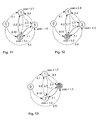
Figure 7 ,vertex 2 has two edges tovertices Figure 7 . The cost to reachvertex 1 is equal to (6,8) which is not equal to or worse than any entry of r 1. It is, therefore, entered into the
vertex 3 is equal to (1,7) which is worse than the cost (9,5) in the f3 list. Therefore, according to Rule 1b) it is discarded.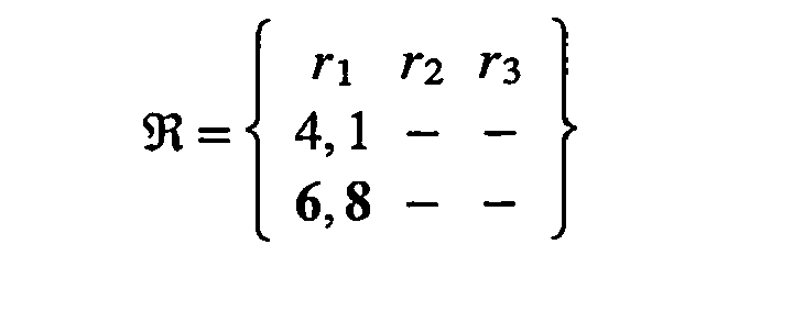
- The widest bandwidth value corresponds to vertex 1: 6,8. This value is moved from the

vertex 1.
- The method now proceeds to
vertex 1 with an associated cost of 6,8 - Referring now to
Figure 8 ,vertex 1 has two edges tovertices vertex 2 is equal to (2,9) which is worse than the cost (7,6) in the f 2 list. Therefore, according to Rule 1b), it is discarded. The cost to reachvertex 3 is equal to (3,11) which is worse than the cost (9,5) in the f 3 list. Therefore, according to Rule 1b) it is discarded.
- The widest bandwidth value corresponds to
vertex 1. This value is moved from the
vertex 1.
- The process now proceeds to
vertex 1 with an associated cost of 4,1,. - Referring to
Figure 9 ,vertex 1 has two edges tovertices vertex 2 is equal to (2,2) which is not equal or worse than any entry of f 2. It is, therefore, entered in the
vertex 3 is equal to (3,4) which is not equal or worse than any entry of f 3. It is therefore entered in the

- The widest bandwidth value corresponds to vertex 3: 3,4. This value is moved from the


- The method now proceeds to
vertex 3 with an associated cost of 3,4. - Referring now to
Figure 10 ,vertex 3 has two edges tovertices vertex 1 is equal to (3,8) which is worse than the cost (4,1) in the f 1 list. Therefore, according to Rule 1b), it is discarded. However, the cost to reachvertex 2 is equal to (3,5) which is not equal to or worse than any entry of f 2 or r 2. It is therefore entered in the

- The widest bandwidth value corresponds to vertex 2: 3,5. This value is moved from the

vertex 2.
- The method now proceeds to
vertex 2 with an associated cost of 3,5. - Referring to
Figure 11 ,vertex 2 has two edges tovertices vertex 1 is equal to (3,7) which is worse than the cost (4,1) in the f 1 list. Therefore, according to Rule 1b), it is discarded. The cost to reachvertex 3 is equal to (1,6) which is worse than the cost (3,4) in the f 3 list. Therefore, according to Rule 1b), it is discarded.
- The widest bandwidth value corresponds to vertex 2: 2,2. This value is moved from the

vertex 2.
- The method proceeds now to
vertex 2 with associated cost of 2,2. - Referring now to
Figure 12 ,vertex 2 has two edges tovertices vertex 1 is equal to (2,4) which is worse than the cost (4,1) in the f 1 list. Therefore, according to Rule 1b), it is discarded. However, the cost to reachvertex 3 is equal to (1,3) which is not equal to or worse than any entry in the f 3 list. It is therefore entered in the

- The widest bandwidth value corresponds to vertex 3:1,3. This value is moved from then

vertex 3.
- The method proceeds to
vertex 3 with an associated cost of 1,3. - Referring now to
Figure 13 ,vertex 3. Has twoedges vertex 1 is equal to (1,7) which is worse than the cost (4,1) in the f 1 list. Therefore, according to Rule 1b), it is discarded. The cost to reachvertex 2 is equal to (1,4) which is worse than the cost (2,2) in the f 2 list. Consequently, according to Rule 1b), it is discarded.
- As there are no more entries left in the

- The efficient frontiers from
vertex 0 tovertices 
-
Figure 14 to 16 graphically illustrate the efficient frontiers fromvertex 0 tovertices - Referring now to
Figure 17 , in a preferred embodiment of the present invention, there is provided a computer program element comprising computer program code which, when loaded in a processor of a data processing system, configures the processor to perform a method for deriving a set of efficient path costs for a group of nodes comprising a source node and a plurality of destination nodes in a data communications networks, wherein the path costs for paths between nodes in the group are defined in the network and each path cost comprises a restrictive cost such as a value indicative of available bandwidth and an additive cost such as a value indicative of transit delay. - The method comprises, at
step 10, recording, in a first data set in a memory of the data processing system, the path costs for direct paths from the source node to any of the destination nodes. Each recorded cost is associated in the first data set with the node reached by the corresponding path. - At
step 20, the best path cost is selected from the first data set. The best path cost is determined as that comprising the best restrictive cost, or, if a plurality of the path costs comprise equal restrictive costs, the or a path cost having the best restrictive cost and the best additive cost. If for example, the restrictive cost is a value indicative of bandwidth, the best restrictive cost is the cost indicative of the maximum bandwidth. Similarly, if the additive cost is a value indicative of transit delay, the best additive cost is the cost indicative of minimum transit delay. - At
step 30, the best path cost selected instep 20 is recorded in a second data set in the memory of the data processing system. The recorded cost is associated in the second data set with the node reached by the corresponding path. - At
step 40, the cost recorded instep 30 in the second data set is eliminated from the first data set. The elimination may involve deletion, flagging, or any other action for excluding the cost from further consideration. - At
step 50, the cumulative path costs for direct paths from the destination node reached by the path corresponding to the cost recorded instep 30 to any other node in the group are recorded in the first data set. Each recorded cumulative path cost is associated in the first data set with the node reached by the corresponding path. - At
step 60, for each node for which an associated cost was recorded in first data set instep 50, the costs associated with that node in the first and second data sets are compared. Any such cost for reaching that node which has both a worse restrictive cost and a worse additive cost than any other such cost for reaching that node, or any such cost for reaching that node which has an equal restrictive and a worse additive cost than any other such cost for reaching that node, is eliminated from the first data set. - At
step 70, steps 20 to 60 are repeated until no costs remain in the first data set afterstep 60. Atstep 80, the resulting second data set comprises the set of efficient costs. In other words, the set of efficient costs comprises the efficient frontiers for the source node. It will be appreciated that the data processing system may be arouter, switch, bridge, brouter, hub, or any other data networking device that transmits or receives information in a communications network. - Referring now to
Figure 18 , in another embodiment of the present invention, there is provided adata networking device 100 comprising input/output (I/O)ports 110 for connection to adata communications network 170, aprocessor 120 coupled to the I/O ports 110, and amemory 130 connected to the processor. The memory comprises space allocated to storage of afirst data set 140, space allocated to storage of asecond data set 150, and controllogic program code 160. In operation, the data networking device derives a set of efficient path costs for a group nodes comprising a source node and a plurality of destination nodes in a data communications network. The data processing device may embody the source node of the data communications network. The path costs for paths between nodes in the group are defined in the network and each path cost comprises a restrictive cost and an additive cost. In operation, thecontrol logic 160 configures the processor to: - a) record, in the
first data set 140, the path costs for direct paths from the source node to any of the destination nodes, each recorded cost being associated in the first data set with the node reached by the corresponding path; - b) select the best path cost from the
first data set 140, wherein the best path cost is determined as that comprising the best restrictive cost, or, if a plurality of the path costs comprise equal restrictive costs, the or a path cost having the best restrictive cost and the best additive cost; - c) record the best path cost selected in step b) in the
second data set 150, the recorded cost being associated in thesecond data set 150 with the node reached by the corresponding path; - d) eliminate the cost recorded in step c) in the
second data set 150 from thefirst data set 140; - e) in the
first data set 140, record the cumulative path costs for direct paths from the destination node reached by the path corresponding to the cost recorded in step c) to any other node in the group, each recorded cumulative path cost being associated with the node reached by the corresponding path; - f) for each node for which an associated cost was recorded in first data set in step e) compare the costs associated with that node in the
first data set 140 and thesecond data set 150 and eliminating from thefirst data set 140 any such cost for reaching that node which has both a worse restrictive cost and a worse additive cost than any other such cost for reaching that node or any such cost for reaching that node which has an equal restrictive and a worse additive cost than any other such cost for reaching that node; and, - g) repeat steps b) to f) until no costs remain in the first data set after step f).
- The resulting second data set comprises the set of efficient costs. Although, in the embodiment of the present invention hereinbefore described with reference to
Figure 18 , thecontrol logic 160 is computer program code, it will be appreciated that, in other embodiments of the present invention, the control logic may be at least partially implemented in hardwired logic circuitry. It will also be appreciated that at least one of the paths may comprise a plurality of links and at least one intermediate node. - By way of summary, in the preferred embodiments of the present invention hereinbefore described, a set of efficient path costs are derived for a group of nodes comprising a source node and a plurality of destination nodes in a data communications networks, wherein the path costs for paths between nodes in the group are defined in the network and each path cost comprises a restrictive cost and an additive cost, comprises iteratively identifying the paths of higher bandwidth first and, when two or more paths of equal bandwidth are encountered, selecting the path having a lower transit delay associated therewith.
Go back to Step.
Claims (11)
- A method for deriving a set of efficient path costs for a group of nodes comprising a source node and a plurality of destination nodes of a routing domain in a data communications networks, wherein the path costs for paths between nodes in the group are defined in the network and each path cost comprises a restrictive cost and an additive cost, the method comprising:a) recording (10), in a first data set, the path costs for direct paths from the source node to any of the destination nodes, each recorded cost being associated in the first data set with the node reached by the corresponding path;b) selecting (20) the best path cost from the first data set, wherein the best path cost is determined as that comprising the best restrictive cost, or, if a plurality of the path costs comprise equal restrictive costs, the or a path cost having the best restrictive cost and the best additive cost;c) recording (30) the best path cost selected in step b) in a second data set, the recorded cost being associated in the second data set with the node reached by the corresponding path;d) eliminating (40) the cost recorded in step c) in the second data set from the first data set;e) in the first data set, recording (50) the cumulative path costs for direct paths from the destination node reached by the path corresponding to the cost recorded in step c) to any other node in the group, each recorded cumulative path cost being associated in the first data set with the node reached by the corresponding path;f) for each node for which an associated cost was recorded in first data set in step e) comparing (60) the costs associated with that node in the first and second data sets and eliminating from the first data set any such cost for reaching that node which has both a worse restrictive cost and a worse additive cost than any other such cost for reaching that node or any such cost for reaching that node which has an equal restrictive and a worse additive cost than any other such cost for reaching that node; andg) repeating (70) steps b) to f) until no costs remain in the first data set after step f);whereby the resulting second data set comprises the set of efficient costs comprising the efficient frontiers for the source node of the routing domain.
- A method as claimed in claim 1, wherein each restrictive cost comprises a value indicative of bandwidth of the corresponding path; and the best restrictive cost is the cost indicative of the maximum bandwidth.
- A method as claimed in claim 1 or claim 2, wherein each additive cost comprises a value indicative of transit delay associated with the corresponding path and the best additive cost is the cost indicative of the minimum transit delay.
- A method as claimed in any preceding claim, wherein at least one of the paths comprises a plurality of links and at least one intermediate node.
- A computer program element comprising computer program code means which, when loaded in a processor (120) of a data processing system, configures the processor (120) to perform the method for deriving a set of efficient path costs as claimed in any one of claims 1 to 4.
- Apparatus (120, 130) for deriving a set of efficient path costs for a group of nodes comprising a source node and a plurality of destination nodes of a routing domain in a data communications networks (170), wherein the path costs for paths between nodes in the group are defined in the network (170) and each path cost comprises a restrictive cost and an additive cost, the apparatus (120, 130) comprising memory (130) for storing first and second data sets of the path costs and control logic (160) configured to:a) record (10), in the first data set, the path costs for direct paths from the source node to any of the destination nodes, each recorded cost being associated in the first data set with the node reached by the corresponding path;b) select (20) the best path cost from the first data set, wherein the best path cost is determined as that comprising the best restrictive cost, or, if a plurality of the path costs comprise equal restrictive costs, the or a path cost having the best restrictive cost and the best additive cost;c) record (30) the best path cost selected in step b) in the second data set, the recorded cost being associated in the second data set with the node reached by the corresponding path;d) eliminate (40) the cost recorded in step c) in the second data set from the first data set;e) in the first data set, record (50) the cumulative path costs for direct paths from the destination node reached by the path corresponding to the cost recorded in step c) to any other node in the group, each recorded cumulative path cost being associated in the first data set with the node reached by the corresponding path;f) for each node for which an associated cost was recorded in first data set in step e) compare (60) the costs associated with that node in the first and second data sets and eliminating from the first data set any such cost for reaching that node which has both a worse restrictive cost and a worse additive cost than any other such cost for reaching that node or any such cost for reaching that node which has an equal restrictive and a worse additive cost than any other such cost for reaching that node; and,g) repeat (70) steps b) to f) until no costs remain in the first data set after step f);whereby the resulting second data set comprises the set of efficient costs comprising the efficient frontiers for the source node of the routing domain.
- Apparatus (120, 130) as claimed in claim 6, wherein each restrictive cost comprises a value indicative of bandwidth of the corresponding path; and the best restrictive cost is the cost indicative of the maximum bandwidth.
- Apparatus (120, 130) as claimed in claim 6 or claim 7, wherein each additive cost comprises a value indicative of transit delay associated with the corresponding path and the best additive cost is the cost indicative of the minimum transit delay.
- Apparatus (120, 130) as claimed in any of claims 6 to 8, wherein at least one of the paths comprises a plurality of links and at least one intermediate node.
- A data networking device (100) comprising a plurality of ports (110) each for connection to a path of a data communications network (170), and apparatus (120, 130) for deriving a set of efficient path costs as claimed in any of claims 6 to 9 coupled to the paths.
- A data network (170) comprising a plurality of nodes interconnected by plurality of paths, at least one of the nodes comprising a data networking device (100) as claimed in claim 10.
Priority Applications (1)
| Application Number | Priority Date | Filing Date | Title |
|---|---|---|---|
| EP01980810A EP1336274B1 (en) | 2000-11-21 | 2001-11-12 | Routing costs in data networks |
Applications Claiming Priority (4)
| Application Number | Priority Date | Filing Date | Title |
|---|---|---|---|
| EP00811104 | 2000-11-21 | ||
| EP00811104 | 2000-11-21 | ||
| EP01980810A EP1336274B1 (en) | 2000-11-21 | 2001-11-12 | Routing costs in data networks |
| PCT/IB2001/002078 WO2002043324A2 (en) | 2000-11-21 | 2001-11-12 | Routing costs in data networks |
Publications (2)
| Publication Number | Publication Date |
|---|---|
| EP1336274A2 EP1336274A2 (en) | 2003-08-20 |
| EP1336274B1 true EP1336274B1 (en) | 2012-03-21 |
Family
ID=8175042
Family Applications (1)
| Application Number | Title | Priority Date | Filing Date |
|---|---|---|---|
| EP01980810A Expired - Lifetime EP1336274B1 (en) | 2000-11-21 | 2001-11-12 | Routing costs in data networks |
Country Status (9)
| Country | Link |
|---|---|
| US (1) | US7355980B2 (en) |
| EP (1) | EP1336274B1 (en) |
| JP (1) | JP3762748B2 (en) |
| KR (1) | KR100544008B1 (en) |
| CN (1) | CN1220353C (en) |
| AU (1) | AU2002212596A1 (en) |
| BR (1) | BR0115551A (en) |
| TW (1) | TW561747B (en) |
| WO (1) | WO2002043324A2 (en) |
Families Citing this family (84)
| Publication number | Priority date | Publication date | Assignee | Title |
|---|---|---|---|---|
| FI20011392L (en) * | 2001-06-28 | 2002-12-29 | Nokia Corp | Mechanism for multicast distribution in a telecommunications system |
| US7145878B2 (en) * | 2001-07-27 | 2006-12-05 | Corrigent Systems Ltd. | Avoiding overlapping segments in transparent LAN services on ring-based networks |
| US7283478B2 (en) * | 2001-11-28 | 2007-10-16 | Corrigent Systems Ltd. | Traffic engineering in bi-directional ring networks |
| US7499404B2 (en) * | 2002-08-30 | 2009-03-03 | Nortel Networks Limited | Distributed quality of service routing |
| US7792991B2 (en) * | 2002-12-17 | 2010-09-07 | Cisco Technology, Inc. | Method and apparatus for advertising a link cost in a data communications network |
| US7707307B2 (en) * | 2003-01-09 | 2010-04-27 | Cisco Technology, Inc. | Method and apparatus for constructing a backup route in a data communications network |
| US7869350B1 (en) | 2003-01-15 | 2011-01-11 | Cisco Technology, Inc. | Method and apparatus for determining a data communication network repair strategy |
| US7336605B2 (en) | 2003-05-13 | 2008-02-26 | Corrigent Systems, Inc. | Bandwidth allocation for link aggregation |
| US7330440B1 (en) | 2003-05-20 | 2008-02-12 | Cisco Technology, Inc. | Method and apparatus for constructing a transition route in a data communications network |
| US7864708B1 (en) | 2003-07-15 | 2011-01-04 | Cisco Technology, Inc. | Method and apparatus for forwarding a tunneled packet in a data communications network |
| US6937579B2 (en) * | 2003-07-25 | 2005-08-30 | International Business Machines Corporation | Electronic device connection resource management |
| US7466661B1 (en) | 2003-09-22 | 2008-12-16 | Cisco Technology, Inc. | Method and apparatus for establishing adjacency for a restarting router during convergence |
| US7554921B2 (en) * | 2003-10-14 | 2009-06-30 | Cisco Technology, Inc. | Method and apparatus for generating routing information in a data communication network |
| US7580360B2 (en) * | 2003-10-14 | 2009-08-25 | Cisco Technology, Inc. | Method and apparatus for generating routing information in a data communications network |
| US7710882B1 (en) | 2004-03-03 | 2010-05-04 | Cisco Technology, Inc. | Method and apparatus for computing routing information for a data communications network |
| GB0407144D0 (en) * | 2004-03-30 | 2004-05-05 | British Telecomm | Networks |
| US7848240B2 (en) * | 2004-06-01 | 2010-12-07 | Cisco Technology, Inc. | Method and apparatus for forwarding data in a data communications network |
| US7418000B2 (en) * | 2004-06-03 | 2008-08-26 | Corrigent Systems Ltd. | Automated weight calculation for packet networks |
| US8843978B2 (en) | 2004-06-29 | 2014-09-23 | Time Warner Cable Enterprises Llc | Method and apparatus for network bandwidth allocation |
| US7577106B1 (en) | 2004-07-12 | 2009-08-18 | Cisco Technology, Inc. | Method and apparatus for managing a transition for a class of data between first and second topologies in a data communications network |
| US7330431B2 (en) * | 2004-09-03 | 2008-02-12 | Corrigent Systems Ltd. | Multipoint to multipoint communication over ring topologies |
| US7630298B2 (en) * | 2004-10-27 | 2009-12-08 | Cisco Technology, Inc. | Method and apparatus for forwarding data in a data communications network |
| US7496644B2 (en) * | 2004-11-05 | 2009-02-24 | Cisco Technology, Inc. | Method and apparatus for managing a network component change |
| US7974223B2 (en) * | 2004-11-19 | 2011-07-05 | Corrigent Systems Ltd. | Virtual private LAN service over ring networks |
| US7567565B2 (en) | 2005-02-01 | 2009-07-28 | Time Warner Cable Inc. | Method and apparatus for network bandwidth conservation |
| US7656886B2 (en) * | 2005-02-07 | 2010-02-02 | Chin-Tau Lea | Non-blocking internet backbone network |
| US9306831B2 (en) * | 2005-02-14 | 2016-04-05 | Cisco Technology, Inc. | Technique for efficient load balancing of TE-LSPs |
| US7933197B2 (en) * | 2005-02-22 | 2011-04-26 | Cisco Technology, Inc. | Method and apparatus for constructing a repair path around a non-available component in a data communications network |
| US7848224B2 (en) * | 2005-07-05 | 2010-12-07 | Cisco Technology, Inc. | Method and apparatus for constructing a repair path for multicast data |
| US7835312B2 (en) * | 2005-07-20 | 2010-11-16 | Cisco Technology, Inc. | Method and apparatus for updating label-switched paths |
| US7693043B2 (en) * | 2005-07-22 | 2010-04-06 | Cisco Technology, Inc. | Method and apparatus for advertising repair capability |
| NZ541666A (en) * | 2005-08-05 | 2008-09-26 | Elizabeth Cramer | Methods of modulating apoptosis and platelet production using an isolated oligonucleotide, its compliment, a vector with the expression sequence or an isolated polypeptide all relating to cytochrome C |
| US7978611B2 (en) * | 2005-09-06 | 2011-07-12 | At&T Intellectual Property I, L.P. | Systems and methods to determine network routes based on transmission medium length |
| US7898957B2 (en) * | 2005-10-03 | 2011-03-01 | The Hong Kong University Of Science And Technology | Non-blocking destination-based routing networks |
| US7983150B2 (en) * | 2006-01-18 | 2011-07-19 | Corrigent Systems Ltd. | VPLS failure protection in ring networks |
| US8111618B2 (en) | 2006-01-27 | 2012-02-07 | Alcatel Lucent | End-to-end service quality using source-routed probes |
| US8170065B2 (en) | 2006-02-27 | 2012-05-01 | Time Warner Cable Inc. | Methods and apparatus for selecting digital access technology for programming and data delivery |
| US8458753B2 (en) | 2006-02-27 | 2013-06-04 | Time Warner Cable Enterprises Llc | Methods and apparatus for device capabilities discovery and utilization within a content-based network |
| US7808931B2 (en) * | 2006-03-02 | 2010-10-05 | Corrigent Systems Ltd. | High capacity ring communication network |
| US7593400B2 (en) * | 2006-05-19 | 2009-09-22 | Corrigent Systems Ltd. | MAC address learning in a distributed bridge |
| US9386327B2 (en) | 2006-05-24 | 2016-07-05 | Time Warner Cable Enterprises Llc | Secondary content insertion apparatus and methods |
| US8280982B2 (en) | 2006-05-24 | 2012-10-02 | Time Warner Cable Inc. | Personal content server apparatus and methods |
| US8024762B2 (en) | 2006-06-13 | 2011-09-20 | Time Warner Cable Inc. | Methods and apparatus for providing virtual content over a network |
| US7660303B2 (en) | 2006-08-22 | 2010-02-09 | Corrigent Systems Ltd. | Point-to-multipoint functionality in a bridged network |
| US7701845B2 (en) | 2006-09-25 | 2010-04-20 | Cisco Technology, Inc. | Forwarding data in a data communications network |
| US8014291B2 (en) | 2006-11-28 | 2011-09-06 | Cisco Technology, Inc. | Relaxed constrained shortest path first (R-CSPF) |
| US8181206B2 (en) | 2007-02-28 | 2012-05-15 | Time Warner Cable Inc. | Personal content server apparatus and methods |
| US20080235746A1 (en) | 2007-03-20 | 2008-09-25 | Michael James Peters | Methods and apparatus for content delivery and replacement in a network |
| US7940776B2 (en) * | 2007-06-13 | 2011-05-10 | Cisco Technology, Inc. | Fast re-routing in distance vector routing protocol networks |
| KR100905650B1 (en) * | 2007-08-01 | 2009-06-30 | 에스케이 텔레콤주식회사 | Routing cost error detection method of signal route and network management system for same |
| US7948897B2 (en) | 2007-08-15 | 2011-05-24 | Adc Telecommunications, Inc. | Delay management for distributed communications networks |
| US8561116B2 (en) | 2007-09-26 | 2013-10-15 | Charles A. Hasek | Methods and apparatus for content caching in a video network |
| US9071859B2 (en) | 2007-09-26 | 2015-06-30 | Time Warner Cable Enterprises Llc | Methods and apparatus for user-based targeted content delivery |
| US8099757B2 (en) * | 2007-10-15 | 2012-01-17 | Time Warner Cable Inc. | Methods and apparatus for revenue-optimized delivery of content in a network |
| US9503691B2 (en) | 2008-02-19 | 2016-11-22 | Time Warner Cable Enterprises Llc | Methods and apparatus for enhanced advertising and promotional delivery in a network |
| US8813143B2 (en) | 2008-02-26 | 2014-08-19 | Time Warner Enterprises LLC | Methods and apparatus for business-based network resource allocation |
| US8270316B1 (en) * | 2009-01-30 | 2012-09-18 | The Regents Of The University Of California | On-chip radio frequency (RF) interconnects for network-on-chip designs |
| US9866609B2 (en) | 2009-06-08 | 2018-01-09 | Time Warner Cable Enterprises Llc | Methods and apparatus for premises content distribution |
| US9178634B2 (en) | 2009-07-15 | 2015-11-03 | Time Warner Cable Enterprises Llc | Methods and apparatus for evaluating an audience in a content-based network |
| US8813124B2 (en) | 2009-07-15 | 2014-08-19 | Time Warner Cable Enterprises Llc | Methods and apparatus for targeted secondary content insertion |
| US8701138B2 (en) | 2010-04-23 | 2014-04-15 | Time Warner Cable Enterprises Llc | Zone control methods and apparatus |
| CN102347886A (en) * | 2010-07-30 | 2012-02-08 | 鸿富锦精密工业(深圳)有限公司 | Client and method for client to select optimal communication path |
| US8542578B1 (en) | 2010-08-04 | 2013-09-24 | Cisco Technology, Inc. | System and method for providing a link-state path to a node in a network environment |
| US8856846B2 (en) * | 2010-11-29 | 2014-10-07 | At&T Intellectual Property I, L.P. | Content placement |
| CN102055675B (en) * | 2011-01-21 | 2012-12-19 | 清华大学 | Multipath routing distribution method based on load equilibrium |
| US20120250535A1 (en) * | 2011-03-31 | 2012-10-04 | Microsoft Corporation | Hub label based routing in shortest path determination |
| US8743718B2 (en) | 2011-06-21 | 2014-06-03 | Adc Telecommunications, Inc. | End-to-end delay management for distributed communications networks |
| US9078040B2 (en) | 2012-04-12 | 2015-07-07 | Time Warner Cable Enterprises Llc | Apparatus and methods for enabling media options in a content delivery network |
| US9854280B2 (en) | 2012-07-10 | 2017-12-26 | Time Warner Cable Enterprises Llc | Apparatus and methods for selective enforcement of secondary content viewing |
| US8862155B2 (en) | 2012-08-30 | 2014-10-14 | Time Warner Cable Enterprises Llc | Apparatus and methods for enabling location-based services within a premises |
| US9131283B2 (en) | 2012-12-14 | 2015-09-08 | Time Warner Cable Enterprises Llc | Apparatus and methods for multimedia coordination |
| US20140282786A1 (en) | 2013-03-12 | 2014-09-18 | Time Warner Cable Enterprises Llc | Methods and apparatus for providing and uploading content to personalized network storage |
| US9450689B2 (en) | 2013-10-07 | 2016-09-20 | Commscope Technologies Llc | Systems and methods for delay management in distributed antenna system with direct digital interface to base station |
| US9832500B2 (en) | 2014-07-05 | 2017-11-28 | TiltedGlobe LLC | System for enabling a virtual theater |
| US10028025B2 (en) | 2014-09-29 | 2018-07-17 | Time Warner Cable Enterprises Llc | Apparatus and methods for enabling presence-based and use-based services |
| US10586023B2 (en) | 2016-04-21 | 2020-03-10 | Time Warner Cable Enterprises Llc | Methods and apparatus for secondary content management and fraud prevention |
| US11120343B2 (en) * | 2016-05-11 | 2021-09-14 | Cisco Technology, Inc. | Intelligent anomaly identification and alerting system based on smart ranking of anomalies |
| US10687115B2 (en) | 2016-06-01 | 2020-06-16 | Time Warner Cable Enterprises Llc | Cloud-based digital content recorder apparatus and methods |
| US11212593B2 (en) | 2016-09-27 | 2021-12-28 | Time Warner Cable Enterprises Llc | Apparatus and methods for automated secondary content management in a digital network |
| US10911794B2 (en) | 2016-11-09 | 2021-02-02 | Charter Communications Operating, Llc | Apparatus and methods for selective secondary content insertion in a digital network |
| US11109290B2 (en) | 2017-08-04 | 2021-08-31 | Charter Communications Operating, Llc | Switching connections over frequency bands of a wireless network |
| US10939142B2 (en) | 2018-02-27 | 2021-03-02 | Charter Communications Operating, Llc | Apparatus and methods for content storage, distribution and security within a content distribution network |
| US20240214297A1 (en) * | 2022-12-27 | 2024-06-27 | Nokia Solutions And Networks Oy | Autonomous path construction and routing |
| US12609767B2 (en) * | 2023-11-26 | 2026-04-21 | Xieon Networks S.A.R.L. | System and method for providing transient resilient transmissions in an optical network |
Family Cites Families (6)
| Publication number | Priority date | Publication date | Assignee | Title |
|---|---|---|---|---|
| US6088436A (en) * | 1994-10-11 | 2000-07-11 | Anip, Inc. | Automated callback system |
| US5754543A (en) | 1996-07-03 | 1998-05-19 | Alcatel Data Networks, Inc. | Connectivity matrix-based multi-cost routing |
| DE69840844D1 (en) | 1998-08-10 | 2009-07-02 | Ibm | Abstraction of a "PNNI" topology |
| US6330229B1 (en) * | 1998-11-09 | 2001-12-11 | 3Com Corporation | Spanning tree with rapid forwarding database updates |
| US6195553B1 (en) * | 1999-04-20 | 2001-02-27 | Analytical Graphics, Inc. | Method and apparatus for determining optimal paths among objects of a communications network |
| US6414951B1 (en) * | 1999-10-08 | 2002-07-02 | Interdigital Technology Corporation | Method for detecting short codes in CDMA systems |
-
2001
- 2001-03-19 TW TW090106341A patent/TW561747B/en active
- 2001-11-12 KR KR1020037006652A patent/KR100544008B1/en not_active Expired - Fee Related
- 2001-11-12 JP JP2002544926A patent/JP3762748B2/en not_active Expired - Fee Related
- 2001-11-12 WO PCT/IB2001/002078 patent/WO2002043324A2/en not_active Ceased
- 2001-11-12 CN CNB018192467A patent/CN1220353C/en not_active Expired - Fee Related
- 2001-11-12 EP EP01980810A patent/EP1336274B1/en not_active Expired - Lifetime
- 2001-11-12 BR BR0115551-2A patent/BR0115551A/en not_active Application Discontinuation
- 2001-11-12 AU AU2002212596A patent/AU2002212596A1/en not_active Abandoned
- 2001-11-12 US US10/432,453 patent/US7355980B2/en not_active Expired - Fee Related
Also Published As
| Publication number | Publication date |
|---|---|
| JP3762748B2 (en) | 2006-04-05 |
| BR0115551A (en) | 2003-08-19 |
| AU2002212596A1 (en) | 2002-06-03 |
| WO2002043324A2 (en) | 2002-05-30 |
| WO2002043324A3 (en) | 2002-09-06 |
| US7355980B2 (en) | 2008-04-08 |
| CN1220353C (en) | 2005-09-21 |
| KR100544008B1 (en) | 2006-01-20 |
| KR20030059259A (en) | 2003-07-07 |
| JP2004515120A (en) | 2004-05-20 |
| CN1476696A (en) | 2004-02-18 |
| TW561747B (en) | 2003-11-11 |
| EP1336274A2 (en) | 2003-08-20 |
| US20040071089A1 (en) | 2004-04-15 |
Similar Documents
| Publication | Publication Date | Title |
|---|---|---|
| US7355980B2 (en) | Costs in data networks | |
| US6483808B1 (en) | Method of optimizing routing decisions over multiple parameters utilizing fuzzy logic | |
| Gelenbe | Sensible decisions based on QoS | |
| US7397761B2 (en) | Routing restorable service-level-guaranteed connections using maximum 2-route flows | |
| JP3115769B2 (en) | How to assign metric values to each link in the network | |
| Yuan et al. | Heuristic algorithms for multi-constrained quality of service routing | |
| Pióro et al. | On open shortest path first related network optimisation problems | |
| US6584071B1 (en) | Routing with service level guarantees between ingress-egress points in a packet network | |
| US6385201B1 (en) | Topology aggregation using parameter obtained by internodal negotiation | |
| US7889661B2 (en) | Constrained multipath routing method in a multi-protocol label switching (MPLS) network | |
| US6377551B1 (en) | QoS based route determination method for communications networks | |
| Iwata et al. | ATM routing algorithms with multiple QoS requirements for multimedia internetworking | |
| Pióro et al. | On efficient max-min fair routing algorithms | |
| Aboelela et al. | Fuzzy multiobjective routing model in B-ISDN | |
| US20010015958A1 (en) | Complex node representations in PNNI systems | |
| Prasad et al. | AMPF: application-aware multipath packet forwarding using machine learning and SDN | |
| Aboelela et al. | Fuzzy generalized network approach for solving an optimization model for routing in B‐ISDN | |
| EP0892522A1 (en) | Method and arrangement to aggregate parameter information in a hierarchically structured network | |
| Kumar et al. | Routing guaranteed bandwidth virtual paths with simultaneous maximization of additional flows | |
| Xue et al. | Multiconstrained QoS routing: greedy is good | |
| Benhamiche et al. | Toward scalable algorithms for the unsplittable shortest path routing problem | |
| Pasupuleti et al. | Fuzzy system for adaptive network routing | |
| Bauer et al. | Efficient frontier formulation for additive and restrictive metrics in hierarchical routing | |
| Devetak et al. | Minimizing path delay in multipath networks | |
| Saltouros et al. | A Scalable Qos-Based Routing Scheme for ATM Networks Using Reinforcement Learning Algorithms |
Legal Events
| Date | Code | Title | Description |
|---|---|---|---|
| PUAI | Public reference made under article 153(3) epc to a published international application that has entered the european phase |
Free format text: ORIGINAL CODE: 0009012 |
|
| 17P | Request for examination filed |
Effective date: 20030321 |
|
| AK | Designated contracting states |
Designated state(s): AT BE CH CY DE DK ES FI FR GB GR IE IT LI LU MC NL PT SE TR |
|
| AX | Request for extension of the european patent |
Extension state: AL LT LV MK RO SI |
|
| R17D | Deferred search report published (corrected) |
Effective date: 20020906 |
|
| RBV | Designated contracting states (corrected) |
Designated state(s): DE FR GB IE IT |
|
| 17Q | First examination report despatched |
Effective date: 20071214 |
|
| GRAP | Despatch of communication of intention to grant a patent |
Free format text: ORIGINAL CODE: EPIDOSNIGR1 |
|
| GRAS | Grant fee paid |
Free format text: ORIGINAL CODE: EPIDOSNIGR3 |
|
| GRAA | (expected) grant |
Free format text: ORIGINAL CODE: 0009210 |
|
| AK | Designated contracting states |
Kind code of ref document: B1 Designated state(s): DE FR GB IE IT |
|
| REG | Reference to a national code |
Ref country code: GB Ref legal event code: FG4D |
|
| REG | Reference to a national code |
Ref country code: IE Ref legal event code: FG4D |
|
| REG | Reference to a national code |
Ref country code: GB Ref legal event code: 746 Effective date: 20120416 |
|
| REG | Reference to a national code |
Ref country code: DE Ref legal event code: R096 Ref document number: 60146306 Country of ref document: DE Effective date: 20120510 |
|
| REG | Reference to a national code |
Ref country code: DE Ref legal event code: R084 Ref document number: 60146306 Country of ref document: DE Effective date: 20120330 |
|
| PLBE | No opposition filed within time limit |
Free format text: ORIGINAL CODE: 0009261 |
|
| STAA | Information on the status of an ep patent application or granted ep patent |
Free format text: STATUS: NO OPPOSITION FILED WITHIN TIME LIMIT |
|
| 26N | No opposition filed |
Effective date: 20130102 |
|
| PG25 | Lapsed in a contracting state [announced via postgrant information from national office to epo] |
Ref country code: IT Free format text: LAPSE BECAUSE OF FAILURE TO SUBMIT A TRANSLATION OF THE DESCRIPTION OR TO PAY THE FEE WITHIN THE PRESCRIBED TIME-LIMIT Effective date: 20120321 |
|
| REG | Reference to a national code |
Ref country code: DE Ref legal event code: R097 Ref document number: 60146306 Country of ref document: DE Effective date: 20130102 |
|
| REG | Reference to a national code |
Ref country code: IE Ref legal event code: MM4A |
|
| REG | Reference to a national code |
Ref country code: FR Ref legal event code: ST Effective date: 20130731 |
|
| PG25 | Lapsed in a contracting state [announced via postgrant information from national office to epo] |
Ref country code: IE Free format text: LAPSE BECAUSE OF NON-PAYMENT OF DUE FEES Effective date: 20121112 |
|
| PG25 | Lapsed in a contracting state [announced via postgrant information from national office to epo] |
Ref country code: FR Free format text: LAPSE BECAUSE OF NON-PAYMENT OF DUE FEES Effective date: 20121130 |
|
| PGFP | Annual fee paid to national office [announced via postgrant information from national office to epo] |
Ref country code: DE Payment date: 20171207 Year of fee payment: 17 |
|
| PGFP | Annual fee paid to national office [announced via postgrant information from national office to epo] |
Ref country code: GB Payment date: 20171127 Year of fee payment: 17 |
|
| REG | Reference to a national code |
Ref country code: DE Ref legal event code: R119 Ref document number: 60146306 Country of ref document: DE |
|
| GBPC | Gb: european patent ceased through non-payment of renewal fee |
Effective date: 20181112 |
|
| PG25 | Lapsed in a contracting state [announced via postgrant information from national office to epo] |
Ref country code: DE Free format text: LAPSE BECAUSE OF NON-PAYMENT OF DUE FEES Effective date: 20190601 |
|
| PG25 | Lapsed in a contracting state [announced via postgrant information from national office to epo] |
Ref country code: GB Free format text: LAPSE BECAUSE OF NON-PAYMENT OF DUE FEES Effective date: 20181112 |