EP1336010B1 - Vacuum toilet bowl assembly - Google Patents
Vacuum toilet bowl assembly Download PDFInfo
- Publication number
- EP1336010B1 EP1336010B1 EP01980569A EP01980569A EP1336010B1 EP 1336010 B1 EP1336010 B1 EP 1336010B1 EP 01980569 A EP01980569 A EP 01980569A EP 01980569 A EP01980569 A EP 01980569A EP 1336010 B1 EP1336010 B1 EP 1336010B1
- Authority
- EP
- European Patent Office
- Prior art keywords
- bowl
- vacuum
- toilet
- frame
- bowl assembly
- Prior art date
- Legal status (The legal status is an assumption and is not a legal conclusion. Google has not performed a legal analysis and makes no representation as to the accuracy of the status listed.)
- Expired - Lifetime
Links
- 239000012530 fluid Substances 0.000 claims abstract description 21
- 238000004891 communication Methods 0.000 claims abstract description 4
- 239000000463 material Substances 0.000 claims description 8
- 238000003780 insertion Methods 0.000 claims description 4
- 230000037431 insertion Effects 0.000 claims description 4
- 229910000831 Steel Inorganic materials 0.000 claims description 2
- 239000010959 steel Substances 0.000 claims description 2
- 239000002699 waste material Substances 0.000 description 7
- 238000000576 coating method Methods 0.000 description 6
- 239000011248 coating agent Substances 0.000 description 5
- 230000008439 repair process Effects 0.000 description 4
- 230000008878 coupling Effects 0.000 description 3
- 238000010168 coupling process Methods 0.000 description 3
- 238000005859 coupling reaction Methods 0.000 description 3
- 238000012423 maintenance Methods 0.000 description 3
- 239000002184 metal Substances 0.000 description 3
- 229910001220 stainless steel Inorganic materials 0.000 description 2
- 239000010935 stainless steel Substances 0.000 description 2
- 238000012546 transfer Methods 0.000 description 2
- 238000013024 troubleshooting Methods 0.000 description 2
- 235000012206 bottled water Nutrition 0.000 description 1
- 238000010586 diagram Methods 0.000 description 1
- 239000003651 drinking water Substances 0.000 description 1
- 238000000034 method Methods 0.000 description 1
- 238000012986 modification Methods 0.000 description 1
- 230000004048 modification Effects 0.000 description 1
- 230000008569 process Effects 0.000 description 1
- 239000007921 spray Substances 0.000 description 1
- 238000012360 testing method Methods 0.000 description 1
- XLYOFNOQVPJJNP-UHFFFAOYSA-N water Substances O XLYOFNOQVPJJNP-UHFFFAOYSA-N 0.000 description 1
Images

Classifications
-
- E—FIXED CONSTRUCTIONS
- E03—WATER SUPPLY; SEWERAGE
- E03F—SEWERS; CESSPOOLS
- E03F1/00—Methods, systems, or installations for draining-off sewage or storm water
- E03F1/006—Pneumatic sewage disposal systems; accessories specially adapted therefore
-
- E—FIXED CONSTRUCTIONS
- E03—WATER SUPPLY; SEWERAGE
- E03D—WATER-CLOSETS OR URINALS WITH FLUSHING DEVICES; FLUSHING VALVES THEREFOR
- E03D11/00—Other component parts of water-closets, e.g. noise-reducing means in the flushing system, flushing pipes mounted in the bowl, seals for the bowl outlet, devices preventing overflow of the bowl contents; devices forming a water seal in the bowl after flushing, devices eliminating obstructions in the bowl outlet or preventing backflow of water and excrements from the waterpipe
- E03D11/02—Water-closet bowls ; Bowls with a double odour seal optionally with provisions for a good siphonic action; siphons as part of the bowl
Definitions
- the present invention generally relates to toilets and, more particularly, to a waste receptacle for a vacuum toilet system according to the preamble of claim 1.
- a vacuum flush waste disposal system for railcars of this type is known ( US 5 956 780 ), removal and replacement of components are difficult to do and time consuming, as well.
- a further vacuum toilet is known ( EP 0 818 589 A2 ) in which the outer shell is supporting the bowl.
- Vacuum toilet systems are generally known in the art for use in both vehicle and stationary applications.
- a vacuum toilet system typically comprises a bowl for receiving waste having an outlet connected to a vacuum sewer line.
- a discharge valve is disposed between the bowl outlet and vacuum sewer line to selectively establish fluid communication therebetween.
- the vacuum sewer line is connected to a collection tank that is placed under partial vacuum pressure by a vacuum source, such as a vacuum pump.
- a vacuum source such as a vacuum pump.
- Conventional vacuum toilet systems also include a source of rinse fluid and a rinse fluid valve for controlling introduction of rinse fluid into the bowl.
- each sub-system includes one or more components which must be replaced in the event of failure, such components being commonly referred to as line replaceable units (LRUs).
- LRUs line replaceable units
- the entire toilet assembly is defined as the LRU for the vacuum toilet system.
- an airline must stock one or more replacement toilets in case of a toilet failure, so that the replacement toilet may be swapped in for the faulty toilet.
- a "bench test” is then performed on the faulty toilet to determine which components have failed in the toilet.
- the faulty components are then repaired or replaced (which may include significant disassembly and reassembly of the toilet) so that the toilet may be reused on another aircraft.
- Each of the steps performed during a toilet repair is overly difficult and time consuming.
- To remove an entire toilet assembly from an aircraft requires disassembly of at least four self-locking mounting fasteners, an electrical connection, a grounding strap, a potable water line connection, and a waste discharge pipe connection.
- Each connection may be difficult to access, and may require a particular tool in order to loosen and disconnect. The same connections must then be reconnected for the replacement toilet.
- the toilet bowl for example, is typically formed of stainless steel covered with a non-stick coating that is subject to failure.
- the bowl is a structural, load bearing component that is attached to a base support.
- the base support is permanently attached to the bowl and therefore the entire toilet must be removed to replace the coating.
- the bowl is removable from the support base, and therefore fasteners must be removed and the bowl must be disconnected from the rinse fluid and discharge lines.
- the rinse ring or nozzle used to direct rinse fluid into the bowl must be removed.
- the bowl must be removed from all of the other toilet components for a re-coating process, steps of which are performed at high temperatures to remove the old coating and apply a new coating to the toilet bowl surface. Accordingly, replacement of a conventional bowl is overly complicated and time consuming.
- the use of the bowl as a structural, load-bearing member in conventional toilets overly limits the selection of bowl materials. Because the bowl must be capable of supporting the weight of a user and any components mounted thereto, it is typically made of a metal such as stainless steel. Because only rigid materials may be used, the selection of materials for use in conventional toilet bowls is overly limited.
- a waste receptacle for use in a vacuum toilet system having a discharge valve with an inlet according to claim 1.
- the waste receptacle comprises a support structure, and a bowl releasably attached to the support structure, the bowl defining an outlet adapted to engage and seal with the discharge valve outlet.
- a vacuum bowl assembly for use in a vacuum toilet positioned on a support surface and having a discharge valve with an inlet according to claim 12.
- the assembly comprises a frame having a bottom member adapted to engage the support surface, and a top member defining an opening, a pair of slots being formed in the top member.
- a removable bowl has a sidewall sized for insertion into the opening and a flange carrying a pair of tabs sized to lockingly engage the slots, the bowl defining an outlet adapted for fluid communication with the discharge valve inlet.
- a vacuum toilet 10 suitable for use in vehicle including a frame 20 and bowl 36 in accordance with the present invention.
- the vehicle is provided with a sewer line 11, a vacuum tank 13 connected to the sewer line 11, and a vacuum source (not shown) for placing the vacuum tank 13 under partial vacuum pressure.
- the vehicle further includes a source of rinse fluid 15 connected to a rinse fluid supply line 19.
- the toilet 10 preferably includes a discharge valve 70 adapted for connection to the vacuum tank, and a rinse valve 72 adapted for connection to the source of rinse fluid.
- a flush control unit (FCU) 74 is also provided for controlling operation of the discharge valve 70 and rinse valve 72.
- the discharge valve 70, rinse valve 72, and FCU 74 are preferably provided as an integral valve set 8, as described in greater detail in commonly owned and co-pending U.S. Patent Application Serial No. 09/713,870 , entitled "Integrated Valve Set For Vacuum Toilet".
- the frame 20 is provided for supporting the components of the vacuum toilet 10. As best shown with reference to FIGS. 1 A and 1 B, the frame 20 includes a bottom member 24 adapted for attachment to a support surface of the vehicle. Vertical supports 26 extend upwardly from the bottom member 24, and a top member 28 is attached to the vertical supports. The top member 28 is formed with an opening 30 near the front, and two slots 29 near the rear thereof. In the illustrated embodiment, an intermediate support 32 is attached between adjacent vertical supports 26, and a bracket 27 is attached to the bottom member 24.
- the bottom member 24, top member 28, and bracket 27 are preferably formed of sheet metal, while the vertical supports 26 and intermediate support 32 are preferably formed of tube steel, both of which are readily available and inexpensive. Other materials having sufficient rigidity, however, may also be used.
- the bowl 36 is provided for receiving waste material.
- the bowl 36 has a curved sidewall 38 and an out-turned flange 40 extending about an upper edge of the sidewall (FIGS. 1 A and 1B).
- the out-turned flange 40 further includes tabs 39 sized for insertion through the slots 29 formed in the frame top member 28, as best shown in FIG. 4.
- a bottom of the sidewall is formed in an outlet 42, and the sidewall 38 is sized for insertion into the opening 30 of the frame top member 28.
- the outlet 42 fluidly communicates with the discharge valve 70 through a transfer pipe 44.
- the transfer pipe 44 preferably includes a collar 47 sized to frictionally engage and seal with the outlet 42.
- the bowl 36 is inserted through the opening 30 and positioned so that the tabs 39 are aligned with the slots 29 and the outlet 42 is aligned with the collar 47.
- the bowl 36 is lowered so that the tabs 39 pass through and lock with the slots 29.
- the outlet 42 is inserted into and engages the collar 47.
- the out-turned flange 40 closely overlies the frame top member 28 so that downward forces applied to the bowl 36 are transferred to the frame 20.
- the bowl 36 is not a load-bearing component, and may be made of non-structural materials such as plastic, thin-walled metal (defined herein as less than approximately 1 mm (approximately 0.040") thick), or other known alternatives.
- the bowl 36 is separable from the frame 20 and therefore may be replaced independently from the rest of the toilet 10.
- the tabs 39 may be manipulated manually, and therefore no tools are required to install or remove the bowl 36.
- At least one rinse fluid dispenser such as nozzles 46, is provided inside the bowl 36 for directing rinse fluid over the surface of the bowl.
- a plurality of nozzles 46 are spaced about the bowl sidewall 38 and are oriented to direct rinse fluid over portions of the bowl surface. The number of nozzles may be more or less than that shown, depending on the size of the bowl surface to be rinsed.
- the phrase "rinse fluid dispenser” includes the illustrated nozzles 46, as well as known substitutes, such as spray rings.
- a vacuum breaker 33 is positioned above the top edge of the bowl 36, and a first rinse fluid pipe 35a extends from the nozzles 46 to the vacuum breaker 33.
- a second rinse fluid pipe 35b extends from the vacuum breaker 33 to the rinse valve 16.
- Quick-disconnect couplings 108a, 108b are provided to connect the first and second rinse fluid pipes 35a, 35b to the vacuum breaker 33.
- the separate frame 20 advantageously allows the bowl 36 to be a line replaceable unit (LRU).
- LRU line replaceable unit
- a maintenance person may simply disconnect the first rinse fluid pipe 35a using the quick disconnect coupling 108a, manipulate the tabs 39 so that the are disengaged from the slots 29, and pull upward on the bowl 36 to remove the bowl 36 from the frame 20.
- a new bowl 36 may then be inserted into the frame 20 as described above, and the first rinse fluid pipe 35a may be connected to the vacuum breaker 33 using the quick-disconnect coupling 108a.
- the bowl replacement process is not only fast, but does not require the use of any tools.
- the frame 20 allows a wider range of materials to be used for the bowl 36, since the frame 20, rather than the bowl 36, supports the load.
Landscapes
- Health & Medical Sciences (AREA)
- Life Sciences & Earth Sciences (AREA)
- Engineering & Computer Science (AREA)
- Hydrology & Water Resources (AREA)
- Public Health (AREA)
- Water Supply & Treatment (AREA)
- Sanitary Device For Flush Toilet (AREA)
- Vehicle Waterproofing, Decoration, And Sanitation Devices (AREA)
Abstract
Description
- The present invention generally relates to toilets and, more particularly, to a waste receptacle for a vacuum toilet system according to the preamble of claim 1.
- A vacuum flush waste disposal system for railcars of this type is known (
US 5 956 780 ), removal and replacement of components are difficult to do and time consuming, as well. - The same is true for a vacuum flush water closet of the state of the art (
US 4 041 554 ) in which an outer shroud member is supporting the components of the closet, espec. the bowl. - A further vacuum toilet is known (
EP 0 818 589 A2 ) in which the outer shell is supporting the bowl. - Vacuum toilet systems are generally known in the art for use in both vehicle and stationary applications. A vacuum toilet system typically comprises a bowl for receiving waste having an outlet connected to a vacuum sewer line. A discharge valve is disposed between the bowl outlet and vacuum sewer line to selectively establish fluid communication therebetween. The vacuum sewer line is connected to a collection tank that is placed under partial vacuum pressure by a vacuum source, such as a vacuum pump. When the discharge valve is opened, material in the bowl is transported to the sewer pipe as a result of the pressure difference between the interior of the bowl and the interior of the sewer line. Conventional vacuum toilet systems also include a source of rinse fluid and a rinse fluid valve for controlling introduction of rinse fluid into the bowl.
- Repair and maintenance of vacuum toilet systems is often overly time consuming and labor intensive. Maintenance concerns are particularly significant in aircraft applications, in which a number of subsystems are installed on board. According to general practice in the airline industry, each sub-system includes one or more components which must be replaced in the event of failure, such components being commonly referred to as line replaceable units (LRUs). Presently, the entire toilet assembly is defined as the LRU for the vacuum toilet system. As a result, an airline must stock one or more replacement toilets in case of a toilet failure, so that the replacement toilet may be swapped in for the faulty toilet. A "bench test" is then performed on the faulty toilet to determine which components have failed in the toilet. The faulty components are then repaired or replaced (which may include significant disassembly and reassembly of the toilet) so that the toilet may be reused on another aircraft.
- Each of the steps performed during a toilet repair is overly difficult and time consuming. To remove an entire toilet assembly from an aircraft requires disassembly of at least four self-locking mounting fasteners, an electrical connection, a grounding strap, a potable water line connection, and a waste discharge pipe connection. Each connection may be difficult to access, and may require a particular tool in order to loosen and disconnect. The same connections must then be reconnected for the replacement toilet.
- Even if it were possible to remove and replace a single toilet component, it would be overly difficult and time consuming to do so. Removal of a component would require disconnection of several wires and pipes, and the components are often located in areas which are difficult to access. Furthermore, it would be difficult to diagnose whether one component or several components had failed. There exists a multitude of combinations of simultaneous component failures, which may lead to trouble-shooting errors and the replacement or repair of non-faulty components.
- Certain repairs, which may not require substantial amounts of trouble shooting to identify the failed components, still require significant amounts of disassembly and reassembly. The toilet bowl, for example, is typically formed of stainless steel covered with a non-stick coating that is subject to failure. In conventional toilets, the bowl is a structural, load bearing component that is attached to a base support. In some toilets, the base support is permanently attached to the bowl and therefore the entire toilet must be removed to replace the coating. In other toilets the bowl is removable from the support base, and therefore fasteners must be removed and the bowl must be disconnected from the rinse fluid and discharge lines. In addition, the rinse ring or nozzle used to direct rinse fluid into the bowl must be removed. Furthermore, if the non-stick coating fails, the bowl must be removed from all of the other toilet components for a re-coating process, steps of which are performed at high temperatures to remove the old coating and apply a new coating to the toilet bowl surface. Accordingly, replacement of a conventional bowl is overly complicated and time consuming.
- In addition, the use of the bowl as a structural, load-bearing member in conventional toilets overly limits the selection of bowl materials. Because the bowl must be capable of supporting the weight of a user and any components mounted thereto, it is typically made of a metal such as stainless steel. Because only rigid materials may be used, the selection of materials for use in conventional toilet bowls is overly limited.
- In accordance with certain aspects of the present invention, a waste receptacle is provided for use in a vacuum toilet system having a discharge valve with an inlet according to claim 1. The waste receptacle comprises a support structure, and a bowl releasably attached to the support structure, the bowl defining an outlet adapted to engage and seal with the discharge valve outlet.
- In accordance with additional aspects of the present invention, a vacuum bowl assembly is provided for use in a vacuum toilet positioned on a support surface and having a discharge valve with an inlet according to claim 12. The assembly comprises a frame having a bottom member adapted to engage the support surface, and a top member defining an opening, a pair of slots being formed in the top member. A removable bowl has a sidewall sized for insertion into the opening and a flange carrying a pair of tabs sized to lockingly engage the slots, the bowl defining an outlet adapted for fluid communication with the discharge valve inlet.
- Other features and advantages are inherent in the apparatus claimed and disclosed or will become apparent to those skilled in the art from the following detailed description, by way of example only, and its accompanying schematic drawings.
-
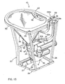
- FIGS. 1A and 1B are front and rear perspective views, respectively, of a vacuum toilet frame and bowl in accordance with the present invention.
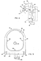
- FIG. 2 is a schematic diagram of the vacuum toilet of FIG. 1.
- FIG. 3 is a top view of the bowl.
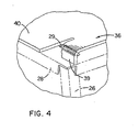
- FIG. 4 is an enlarged view of a tab used to secure the bowl to the frame.
- Referring initially to FIGS. 1A, 1B, and 2, a
vacuum toilet 10 suitable for use in vehicle is shown including aframe 20 andbowl 36 in accordance with the present invention. The vehicle is provided with a sewer line 11, avacuum tank 13 connected to the sewer line 11, and a vacuum source (not shown) for placing thevacuum tank 13 under partial vacuum pressure. The vehicle further includes a source ofrinse fluid 15 connected to a rinsefluid supply line 19. - The
toilet 10 preferably includes adischarge valve 70 adapted for connection to the vacuum tank, and arinse valve 72 adapted for connection to the source of rinse fluid. A flush control unit (FCU) 74 is also provided for controlling operation of thedischarge valve 70 andrinse valve 72. As shown in the illustrated embodiment, thedischarge valve 70,rinse valve 72, and FCU 74 are preferably provided as anintegral valve set 8, as described in greater detail in commonly owned and co-pendingU.S. Patent Application Serial No. 09/713,870 , entitled "Integrated Valve Set For Vacuum Toilet". - The
frame 20 is provided for supporting the components of thevacuum toilet 10. As best shown with reference to FIGS. 1 A and 1 B, theframe 20 includes abottom member 24 adapted for attachment to a support surface of the vehicle.Vertical supports 26 extend upwardly from thebottom member 24, and atop member 28 is attached to the vertical supports. Thetop member 28 is formed with an opening 30 near the front, and twoslots 29 near the rear thereof. In the illustrated embodiment, anintermediate support 32 is attached between adjacentvertical supports 26, and abracket 27 is attached to thebottom member 24. Thebottom member 24,top member 28, andbracket 27 are preferably formed of sheet metal, while the vertical supports 26 andintermediate support 32 are preferably formed of tube steel, both of which are readily available and inexpensive. Other materials having sufficient rigidity, however, may also be used. - The
bowl 36 is provided for receiving waste material. Thebowl 36 has acurved sidewall 38 and an out-turnedflange 40 extending about an upper edge of the sidewall (FIGS. 1 A and 1B). The out-turnedflange 40 further includestabs 39 sized for insertion through theslots 29 formed in theframe top member 28, as best shown in FIG. 4. A bottom of the sidewall is formed in anoutlet 42, and thesidewall 38 is sized for insertion into theopening 30 of theframe top member 28. Theoutlet 42 fluidly communicates with thedischarge valve 70 through atransfer pipe 44. Thetransfer pipe 44 preferably includes acollar 47 sized to frictionally engage and seal with theoutlet 42. - To attach the
bowl 36 to theframe 20, thebowl 36 is inserted through theopening 30 and positioned so that thetabs 39 are aligned with theslots 29 and theoutlet 42 is aligned with thecollar 47. Thebowl 36 is lowered so that thetabs 39 pass through and lock with theslots 29. Simultaneously, theoutlet 42 is inserted into and engages thecollar 47. In this position, the out-turnedflange 40 closely overlies theframe top member 28 so that downward forces applied to thebowl 36 are transferred to theframe 20. As a result, thebowl 36 is not a load-bearing component, and may be made of non-structural materials such as plastic, thin-walled metal (defined herein as less than approximately 1 mm (approximately 0.040") thick), or other known alternatives. In addition, thebowl 36 is separable from theframe 20 and therefore may be replaced independently from the rest of thetoilet 10. Still further, thetabs 39 may be manipulated manually, and therefore no tools are required to install or remove thebowl 36. - At least one rinse fluid dispenser, such as
nozzles 46, is provided inside thebowl 36 for directing rinse fluid over the surface of the bowl. As best shown in FIGS. 1 A and 1 B, a plurality ofnozzles 46 are spaced about thebowl sidewall 38 and are oriented to direct rinse fluid over portions of the bowl surface. The number of nozzles may be more or less than that shown, depending on the size of the bowl surface to be rinsed. As used herein, the phrase "rinse fluid dispenser" includes the illustratednozzles 46, as well as known substitutes, such as spray rings. - A
vacuum breaker 33 is positioned above the top edge of thebowl 36, and a first rinsefluid pipe 35a extends from thenozzles 46 to thevacuum breaker 33. A second rinsefluid pipe 35b extends from thevacuum breaker 33 to the rinsevalve 16. Quick-disconnect couplings 108a, 108b are provided to connect the first and second rinsefluid pipes vacuum breaker 33. - The
separate frame 20 advantageously allows thebowl 36 to be a line replaceable unit (LRU). When thebowl 36 becomes worn or otherwise needs replacement, a maintenance person may simply disconnect the first rinsefluid pipe 35a using the quick disconnect coupling 108a, manipulate thetabs 39 so that the are disengaged from theslots 29, and pull upward on thebowl 36 to remove thebowl 36 from theframe 20. Anew bowl 36 may then be inserted into theframe 20 as described above, and the first rinsefluid pipe 35a may be connected to thevacuum breaker 33 using the quick-disconnect coupling 108a. As a result, the entire toilet need not be removed and serviced. The bowl replacement process is not only fast, but does not require the use of any tools. In addition to facilitating bowl removal and replacement, theframe 20 allows a wider range of materials to be used for thebowl 36, since theframe 20, rather than thebowl 36, supports the load. - The foregoing detailed description has be given for clearness of understanding only, and no unnecessary limitations should be understood therefrom, as modifications would be obvious to those skilled in the art.
Claims (6)
- A vacuum bowl assembly for use in a vacuum toilet (10) positioned on a support surface and having a discharge valve (70) with an inlet, comprising: a frame (20) having a bottom member (24) adapted to engage the support surface, and a top member (28) defining an opening (30) and a removable bowl (36) having a sidewall (38) sized for insertion into the opening (30) and a flange (40), the bowl (36) defining an outlet (42) adapted for fluid communication with the discharge valve (70) inlet characterized in that the frame has a pair of slots (29) being formed in the top member (28) and the flange (40) is carrying a pair of tabs (39) sized to lockingly engage the slots (29).
- The vacuum bowl assembly of claim 1, characterized in that the frame (20) further comprises a bracket (27) adapted to support the discharge valve (70).
- The vacuum bowl assembly of claim 1, characterized in that the bowl (36) is not a load-bearing component.
- The vacuum bowl assembly of claim 1 characterized in that the bowl (36) comprises a plastic material.
- The vacuum bowl assembly of claim 1 characterized in that the bowl (36) comprises a thin-walled steel.
- The vacuum bowl assembly of claim 1 characterized in that the tabs (29) are manually releasable to disengage from the slots (39).
Applications Claiming Priority (3)
| Application Number | Priority Date | Filing Date | Title |
|---|---|---|---|
| US09/713,861 US6347416B1 (en) | 2000-11-16 | 2000-11-16 | Vacuum toilet bowl assembly having a removable bowl |
| US713861 | 2000-11-16 | ||
| PCT/FI2001/000935 WO2002040794A1 (en) | 2000-11-16 | 2001-10-29 | Vacuum toilet bowl assembly |
Publications (2)
| Publication Number | Publication Date |
|---|---|
| EP1336010A1 EP1336010A1 (en) | 2003-08-20 |
| EP1336010B1 true EP1336010B1 (en) | 2007-06-20 |
Family
ID=24867825
Family Applications (1)
| Application Number | Title | Priority Date | Filing Date |
|---|---|---|---|
| EP01980569A Expired - Lifetime EP1336010B1 (en) | 2000-11-16 | 2001-10-29 | Vacuum toilet bowl assembly |
Country Status (7)
| Country | Link |
|---|---|
| US (2) | US6347416B1 (en) |
| EP (1) | EP1336010B1 (en) |
| CN (1) | CN1229555C (en) |
| AT (1) | ATE365250T1 (en) |
| AU (1) | AU2002212383A1 (en) |
| DE (1) | DE60129035T2 (en) |
| WO (1) | WO2002040794A1 (en) |
Families Citing this family (13)
| Publication number | Priority date | Publication date | Assignee | Title |
|---|---|---|---|---|
| USD619228S1 (en) | 2008-10-03 | 2010-07-06 | B/E Aerospace, Inc. | Vacuum waste system |
| CN102171401B (en) * | 2008-10-03 | 2015-06-24 | B/E航空公司 | Vacuum waste system and method for using the same |
| USD619227S1 (en) | 2008-10-03 | 2010-07-06 | B/E Aerospace, Inc. | Bowl for vacuum waste system |
| US9021620B1 (en) | 2009-01-15 | 2015-05-05 | Modular Services Company | Cantilevered brace assembly for wall-mounted toilet |
| USD618775S1 (en) | 2009-09-21 | 2010-06-29 | B/E Aerospace, Inc. | Vacuum waste system |
| US8490223B2 (en) | 2011-08-16 | 2013-07-23 | Flow Control LLC | Toilet with ball valve mechanism and secondary aerobic chamber |
| CA2872859A1 (en) | 2012-05-17 | 2013-11-21 | Mag Aerospace Industries, Inc. | Two-stage flush and grey water flush systems and devices |
| US9371135B2 (en) | 2012-05-17 | 2016-06-21 | Mag Aerospace Industries, Llc | Toilet concepts |
| CA2897487A1 (en) | 2013-01-30 | 2014-08-07 | Mag Aerospace Industries, Inc. | Toilets with improved removability for passenger transport vehicles |
| US10208468B2 (en) | 2015-03-30 | 2019-02-19 | B/E Aerospace, Inc. | Maintenance mode for aircraft vacuum toilet |
| CN105297868A (en) * | 2015-09-30 | 2016-02-03 | 重庆跃发日用品有限公司 | Urinal capable of being conveniently and fast arranged |
| US11078655B2 (en) | 2019-02-19 | 2021-08-03 | B/E Aerospace, Inc. | Vacuum waste system |
| CN110924502A (en) * | 2019-12-30 | 2020-03-27 | 周今隆 | A new type of toilet |
Family Cites Families (21)
| Publication number | Priority date | Publication date | Assignee | Title |
|---|---|---|---|---|
| US3239849A (en) | 1962-03-22 | 1966-03-15 | Liljendahl Sven Algot Joel | Method of hydro-pneumatic conveying, system and apparatus |
| US3860973A (en) * | 1973-04-04 | 1975-01-21 | Itt | Toilet construction |
| US4184506A (en) | 1973-12-29 | 1980-01-22 | Krister Nordberg | Vacuum sewer system |
| US3922730A (en) | 1974-03-11 | 1975-12-02 | Monogram Ind Inc | Recirculating toilet system for use in aircraft or the like |
| US3995328A (en) | 1974-12-13 | 1976-12-07 | The Boeing Company | Vacuum toilet system |
| SE409480B (en) | 1977-12-14 | 1979-08-20 | Electrolux Ab | WAY TO TRANSPORT WASTEWATER BY VACUUM |
| US4275470A (en) | 1979-07-18 | 1981-06-30 | Rogerson Aircraft Controls | Vacuum-flush toilet arrangement for aircraft |
| US4357719A (en) | 1979-08-20 | 1982-11-09 | Rogerson Aircraft Controls | Non recirculating method of disposing of waste products for aircrafts |
| US4521925A (en) | 1982-06-30 | 1985-06-11 | The Boeing Company | Nonrecirculating vacuum flush toilet system utilizing fresh water |
| US4713847B1 (en) | 1987-02-02 | 1996-05-28 | Waertsilae Oy Ab | Vacuum toilet system |
| FI83797C (en) | 1988-10-05 | 1991-08-26 | Nesite Oy | AVLOPPSSYSTEM. |
| US5007117A (en) | 1988-12-21 | 1991-04-16 | Oy Wartsila Ab | Vacuum toilet system with simultaneous rinse and discharge |
| US5133583A (en) | 1989-04-27 | 1992-07-28 | Siecor Corporation | Method for use of mesh type cable pulling grips |
| CA1315491C (en) * | 1989-06-28 | 1993-04-06 | Desmond Maurice Kendall | Sanitary fixtures |
| US5271105A (en) * | 1992-04-02 | 1993-12-21 | Tyler Steven J | Vacuum flush toilet assembly |
| US5604938A (en) * | 1992-04-02 | 1997-02-25 | Norcan Aircraft Corporation | Vacuum flush waste disposal system for railcars |
| US5732417A (en) | 1996-03-12 | 1998-03-31 | Envirovac Inc. | Vaccum toilet system |
| FI100547B (en) * | 1996-07-09 | 1997-12-31 | Evac Int Oy | Vakuumklosett |
| FI105120B (en) | 1998-12-23 | 2000-06-15 | Evac Int Oy | Device for transporting waste |
| US6131596A (en) | 1999-07-09 | 2000-10-17 | Evac International Oy | Automatic vacuum isolation valve network for a vacuum collection system |
| US6152160A (en) | 1999-08-30 | 2000-11-28 | Evac International Oy | Modular vacuum drainage system |
-
2000
- 2000-11-16 US US09/713,861 patent/US6347416B1/en not_active Expired - Lifetime
-
2001
- 2001-10-29 AU AU2002212383A patent/AU2002212383A1/en not_active Abandoned
- 2001-10-29 CN CN01821877.6A patent/CN1229555C/en not_active Expired - Fee Related
- 2001-10-29 DE DE60129035T patent/DE60129035T2/en not_active Expired - Lifetime
- 2001-10-29 AT AT01980569T patent/ATE365250T1/en not_active IP Right Cessation
- 2001-10-29 EP EP01980569A patent/EP1336010B1/en not_active Expired - Lifetime
- 2001-10-29 WO PCT/FI2001/000935 patent/WO2002040794A1/en not_active Ceased
-
2002
- 2002-01-22 US US10/054,061 patent/US6536054B2/en not_active Expired - Lifetime
Also Published As
| Publication number | Publication date |
|---|---|
| US6347416B1 (en) | 2002-02-19 |
| US6536054B2 (en) | 2003-03-25 |
| US20020062519A1 (en) | 2002-05-30 |
| CN1486381A (en) | 2004-03-31 |
| CN1229555C (en) | 2005-11-30 |
| DE60129035D1 (en) | 2007-08-02 |
| EP1336010A1 (en) | 2003-08-20 |
| WO2002040794A1 (en) | 2002-05-23 |
| DE60129035T2 (en) | 2008-02-07 |
| AU2002212383A1 (en) | 2002-05-27 |
| ATE365250T1 (en) | 2007-07-15 |
Similar Documents
| Publication | Publication Date | Title |
|---|---|---|
| US6347416B1 (en) | Vacuum toilet bowl assembly having a removable bowl | |
| EP1336011B1 (en) | Modular vacuum toilet | |
| US5909968A (en) | Vacuum toilet unit | |
| MX2014010372A (en) | Toilet pan body and its method of manufacturing. | |
| NZ246404A (en) | Cyclone separator; inlet construction | |
| US20160272320A1 (en) | Toilet concepts | |
| US20060226649A1 (en) | Adapter for coupling connecting pipes in a commercial aircraft | |
| US9371135B2 (en) | Toilet concepts | |
| US5660720A (en) | Connector system for use with reverse osmosis water purifier | |
| CN111099020A (en) | Improved rear wall for a lavatory block of an aircraft | |
| US5975111A (en) | Waste tank clog removal system | |
| EP3277893B1 (en) | Vacuum toilet system | |
| US20230086368A1 (en) | Shower column assembly | |
| WO2002040795A1 (en) | Valve set for a vacuum toilet | |
| US4524500A (en) | Process for converting a ceramic toilet commode intended to be supplied with an independent water supply pipe into a toilet commode adapted to be supplied with water by an associated tank | |
| JPH09119157A (en) | Toilet bowl device connection structure | |
| US7337789B2 (en) | Cleaning apparatus for exhaust system and method | |
| EP0781366B1 (en) | Water closet with flushing cistern | |
| EP4073325B1 (en) | Sanitary module | |
| CN219411125U (en) | Rotational moulding box type vacuum workstation | |
| EP1013440B1 (en) | Fluid flush system for ink jet printing system | |
| JPH0841953A (en) | Toilet bowl with flush water distributor | |
| GB2350672A (en) | Radiator mounting |
Legal Events
| Date | Code | Title | Description |
|---|---|---|---|
| PUAI | Public reference made under article 153(3) epc to a published international application that has entered the european phase |
Free format text: ORIGINAL CODE: 0009012 |
|
| 17P | Request for examination filed |
Effective date: 20030530 |
|
| AK | Designated contracting states |
Designated state(s): AT BE CH CY DE DK ES FI FR GB GR IE IT LI LU MC NL PT SE TR |
|
| AX | Request for extension of the european patent |
Extension state: AL LT LV MK RO SI |
|
| 17Q | First examination report despatched |
Effective date: 20050614 |
|
| GRAP | Despatch of communication of intention to grant a patent |
Free format text: ORIGINAL CODE: EPIDOSNIGR1 |
|
| GRAS | Grant fee paid |
Free format text: ORIGINAL CODE: EPIDOSNIGR3 |
|
| GRAA | (expected) grant |
Free format text: ORIGINAL CODE: 0009210 |
|
| AK | Designated contracting states |
Kind code of ref document: B1 Designated state(s): AT BE CH CY DE DK ES FI FR GB GR IE IT LI LU MC NL PT SE TR |
|
| PG25 | Lapsed in a contracting state [announced via postgrant information from national office to epo] |
Ref country code: LI Free format text: LAPSE BECAUSE OF FAILURE TO SUBMIT A TRANSLATION OF THE DESCRIPTION OR TO PAY THE FEE WITHIN THE PRESCRIBED TIME-LIMIT Effective date: 20070620 Ref country code: CH Free format text: LAPSE BECAUSE OF FAILURE TO SUBMIT A TRANSLATION OF THE DESCRIPTION OR TO PAY THE FEE WITHIN THE PRESCRIBED TIME-LIMIT Effective date: 20070620 |
|
| REG | Reference to a national code |
Ref country code: GB Ref legal event code: FG4D |
|
| REG | Reference to a national code |
Ref country code: CH Ref legal event code: EP |
|
| REG | Reference to a national code |
Ref country code: IE Ref legal event code: FG4D |
|
| REF | Corresponds to: |
Ref document number: 60129035 Country of ref document: DE Date of ref document: 20070802 Kind code of ref document: P |
|
| PG25 | Lapsed in a contracting state [announced via postgrant information from national office to epo] |
Ref country code: SE Free format text: LAPSE BECAUSE OF FAILURE TO SUBMIT A TRANSLATION OF THE DESCRIPTION OR TO PAY THE FEE WITHIN THE PRESCRIBED TIME-LIMIT Effective date: 20070920 |
|
| ET | Fr: translation filed | ||
| PG25 | Lapsed in a contracting state [announced via postgrant information from national office to epo] |
Ref country code: AT Free format text: LAPSE BECAUSE OF FAILURE TO SUBMIT A TRANSLATION OF THE DESCRIPTION OR TO PAY THE FEE WITHIN THE PRESCRIBED TIME-LIMIT Effective date: 20070620 |
|
| NLV1 | Nl: lapsed or annulled due to failure to fulfill the requirements of art. 29p and 29m of the patents act | ||
| REG | Reference to a national code |
Ref country code: CH Ref legal event code: PL |
|
| PG25 | Lapsed in a contracting state [announced via postgrant information from national office to epo] |
Ref country code: BE Free format text: LAPSE BECAUSE OF FAILURE TO SUBMIT A TRANSLATION OF THE DESCRIPTION OR TO PAY THE FEE WITHIN THE PRESCRIBED TIME-LIMIT Effective date: 20070620 |
|
| PG25 | Lapsed in a contracting state [announced via postgrant information from national office to epo] |
Ref country code: PT Free format text: LAPSE BECAUSE OF FAILURE TO SUBMIT A TRANSLATION OF THE DESCRIPTION OR TO PAY THE FEE WITHIN THE PRESCRIBED TIME-LIMIT Effective date: 20071120 Ref country code: ES Free format text: LAPSE BECAUSE OF FAILURE TO SUBMIT A TRANSLATION OF THE DESCRIPTION OR TO PAY THE FEE WITHIN THE PRESCRIBED TIME-LIMIT Effective date: 20071001 Ref country code: NL Free format text: LAPSE BECAUSE OF FAILURE TO SUBMIT A TRANSLATION OF THE DESCRIPTION OR TO PAY THE FEE WITHIN THE PRESCRIBED TIME-LIMIT Effective date: 20070620 |
|
| PLBE | No opposition filed within time limit |
Free format text: ORIGINAL CODE: 0009261 |
|
| STAA | Information on the status of an ep patent application or granted ep patent |
Free format text: STATUS: NO OPPOSITION FILED WITHIN TIME LIMIT |
|
| PG25 | Lapsed in a contracting state [announced via postgrant information from national office to epo] |
Ref country code: GR Free format text: LAPSE BECAUSE OF FAILURE TO SUBMIT A TRANSLATION OF THE DESCRIPTION OR TO PAY THE FEE WITHIN THE PRESCRIBED TIME-LIMIT Effective date: 20070921 Ref country code: IT Free format text: LAPSE BECAUSE OF FAILURE TO SUBMIT A TRANSLATION OF THE DESCRIPTION OR TO PAY THE FEE WITHIN THE PRESCRIBED TIME-LIMIT Effective date: 20070620 Ref country code: DK Free format text: LAPSE BECAUSE OF FAILURE TO SUBMIT A TRANSLATION OF THE DESCRIPTION OR TO PAY THE FEE WITHIN THE PRESCRIBED TIME-LIMIT Effective date: 20070620 |
|
| 26N | No opposition filed |
Effective date: 20080325 |
|
| PG25 | Lapsed in a contracting state [announced via postgrant information from national office to epo] |
Ref country code: MC Free format text: LAPSE BECAUSE OF NON-PAYMENT OF DUE FEES Effective date: 20071031 |
|
| GBPC | Gb: european patent ceased through non-payment of renewal fee |
Effective date: 20071029 |
|
| PG25 | Lapsed in a contracting state [announced via postgrant information from national office to epo] |
Ref country code: IE Free format text: LAPSE BECAUSE OF NON-PAYMENT OF DUE FEES Effective date: 20071030 |
|
| PG25 | Lapsed in a contracting state [announced via postgrant information from national office to epo] |
Ref country code: GB Free format text: LAPSE BECAUSE OF NON-PAYMENT OF DUE FEES Effective date: 20071029 |
|
| PG25 | Lapsed in a contracting state [announced via postgrant information from national office to epo] |
Ref country code: FI Free format text: LAPSE BECAUSE OF FAILURE TO SUBMIT A TRANSLATION OF THE DESCRIPTION OR TO PAY THE FEE WITHIN THE PRESCRIBED TIME-LIMIT Effective date: 20070620 |
|
| PG25 | Lapsed in a contracting state [announced via postgrant information from national office to epo] |
Ref country code: CY Free format text: LAPSE BECAUSE OF FAILURE TO SUBMIT A TRANSLATION OF THE DESCRIPTION OR TO PAY THE FEE WITHIN THE PRESCRIBED TIME-LIMIT Effective date: 20070620 |
|
| PG25 | Lapsed in a contracting state [announced via postgrant information from national office to epo] |
Ref country code: LU Free format text: LAPSE BECAUSE OF NON-PAYMENT OF DUE FEES Effective date: 20071029 |
|
| PG25 | Lapsed in a contracting state [announced via postgrant information from national office to epo] |
Ref country code: TR Free format text: LAPSE BECAUSE OF FAILURE TO SUBMIT A TRANSLATION OF THE DESCRIPTION OR TO PAY THE FEE WITHIN THE PRESCRIBED TIME-LIMIT Effective date: 20070620 |
|
| REG | Reference to a national code |
Ref country code: FR Ref legal event code: PLFP Year of fee payment: 15 |
|
| REG | Reference to a national code |
Ref country code: FR Ref legal event code: PLFP Year of fee payment: 16 |
|
| REG | Reference to a national code |
Ref country code: FR Ref legal event code: PLFP Year of fee payment: 17 |
|
| REG | Reference to a national code |
Ref country code: FR Ref legal event code: PLFP Year of fee payment: 18 |
|
| PGFP | Annual fee paid to national office [announced via postgrant information from national office to epo] |
Ref country code: DE Payment date: 20181106 Year of fee payment: 18 |
|
| PGFP | Annual fee paid to national office [announced via postgrant information from national office to epo] |
Ref country code: FR Payment date: 20181023 Year of fee payment: 18 |
|
| REG | Reference to a national code |
Ref country code: DE Ref legal event code: R119 Ref document number: 60129035 Country of ref document: DE |
|
| PG25 | Lapsed in a contracting state [announced via postgrant information from national office to epo] |
Ref country code: DE Free format text: LAPSE BECAUSE OF NON-PAYMENT OF DUE FEES Effective date: 20200501 |
|
| PG25 | Lapsed in a contracting state [announced via postgrant information from national office to epo] |
Ref country code: FR Free format text: LAPSE BECAUSE OF NON-PAYMENT OF DUE FEES Effective date: 20191031 |