EP1335629A2 - Spiral acoustic waveguide electroacoustical transducing system - Google Patents
Spiral acoustic waveguide electroacoustical transducing system Download PDFInfo
- Publication number
- EP1335629A2 EP1335629A2 EP03100041A EP03100041A EP1335629A2 EP 1335629 A2 EP1335629 A2 EP 1335629A2 EP 03100041 A EP03100041 A EP 03100041A EP 03100041 A EP03100041 A EP 03100041A EP 1335629 A2 EP1335629 A2 EP 1335629A2
- Authority
- EP
- European Patent Office
- Prior art keywords
- tube
- spiral
- waveguide
- transducer
- shaped channel
- Prior art date
- Legal status (The legal status is an assumption and is not a legal conclusion. Google has not performed a legal analysis and makes no representation as to the accuracy of the status listed.)
- Granted
Links
Images


Classifications
-
- H—ELECTRICITY
- H04—ELECTRIC COMMUNICATION TECHNIQUE
- H04R—LOUDSPEAKERS, MICROPHONES, GRAMOPHONE PICK-UPS OR LIKE ACOUSTIC ELECTROMECHANICAL TRANSDUCERS; ELECTRIC HEARING AIDS; PUBLIC ADDRESS SYSTEMS
- H04R1/00—Details of transducers, loudspeakers or microphones
- H04R1/20—Arrangements for obtaining desired frequency or directional characteristics
- H04R1/22—Arrangements for obtaining desired frequency or directional characteristics for obtaining desired frequency characteristic only
- H04R1/28—Transducer mountings or enclosures modified by provision of mechanical or acoustic impedances, e.g. resonator, damping means
- H04R1/2807—Enclosures comprising vibrating or resonating arrangements
- H04R1/2853—Enclosures comprising vibrating or resonating arrangements using an acoustic labyrinth or a transmission line
- H04R1/2857—Enclosures comprising vibrating or resonating arrangements using an acoustic labyrinth or a transmission line for loudspeaker transducers
Definitions
- This invention relates to acoustic waveguide electroacoustical transducing systems.
- the invention features an acoustic waveguide for transmitting pressure wave energy produced by an electroacoustical transducer in a medium that propagates pressure wave energy.
- the acoustic waveguide has a tube defining a spiral-shaped channel with a length of L.
- the tube has a first end and a second end with a transducer opening for accommodating an electroacoustical transducer located adjacent to the first end of the tube.
- the second end of the tube is open the medium.
- Embodiments may include one or more of the followin g features.
- the spiral-shaped channel may have a smoothly changing curvature with radius. Additionally, the inner walls of the waveguide may be contiguous.
- the effective length of channel L may be approximately one quarter of the wavelength of the lowest frequency pressure wave energy to be transmitted by the waveguide. The lowest frequency to be transmitted corresponds substantially to the frequency below which the output level commences falling substantially continuously with frequency.
- the tube may define a spiral shaped channel that has a rectangular cross section.
- the tube may define a spiral shaped channel that has a rectangular cross section.
- the tube may define a spiral shaped channel that is coiled in a single plane, forming a flat spiral, or coiled in a plurality of planes, forming a helical spiral.
- an acoustic waveguide for transmitting pressure wave energy produced by an electroacoustical transducer in a medium that propagates pressure wave energy
- the waveguide has a tube having a first end and a second end and formed in a spiral configuration.
- the first end of the tube is closed and the second end of the tube is open to the medium and a transducer opening for accommodating an electroacoustical transducer is located on the tube between the first end and second end of the tube.
- the tube defines a first spiral -shaped channel located between the transducer opening of the tube and the first end of the tube and a contiguous second spiral-shaped channel located between the transducer opening of the tube and the second end of the tube.
- Embodiments may include one or more of the following features.
- the first spiral-shaped channel defined by the tube may have a length of 1/3L while the second spiral-shaped channel may have a length of 2/3L.
- the length of the first spiral-shaped channel, 1/3L, plus the length of the second spiral-shaped channel, 2/3L, plus end effect may be approximately equal one quarter of the wavelength of the lowest frequency pressure wave energy to be transmitted by the waveguide.
- the first and second spiral-shaped channels may each have a smoothly changing curvature with radius.
- the inner walls of the tube may be contiguous.
- the first spiral-shaped channel may have substantially the same cross-section as the second spiral-shaped channel.
- the cross section of the first and second spiral -shaped channels may be rectangular.
- the tube may be composed of PVC.
- the tube defining the spiral-shaped channel may be coiled in a single plane, formin g a flat spiral.
- the tube may be coiled in a plurality of planes, forming a helical spiral.
- a transducer housing may be attached to the tube and the tube may have a second transducer opening located between the tube and the transducer housing.
- the tube may be of two-piece construction which may be assembled with screws, bolts, clips, adhesive, glue and the like.
- a system for transmitting pressure wave energy in a medium that propagates pressure wave energy in a maxim m includes an electroacoustical transducer having a vibratile surface and a spiral waveguide.
- Embodiments of the invention may have one or more of the following advantages.
- a spiral waveguide permits a long waveguide channel within a relatively compact structure.
- a long waveguide channel improves the bass response of a loudspeaker system, while a compact structure can be particularly convenient in a loudspeaker system where physical space is limited, such as in an automobile or portable stereo.
- a spiral waveguide does not have any abrupt 90 or 180 degree bends in the channel, which minimizes unwanted turbulence in the waveguide channel.
- a spiral waveguide can also be configured to have an open and a closed end with a transducer positioned at a specific distance between the open and closed end in order to reduce the first peak in frequency response of the acoustic energy transmitted by the waveguide.
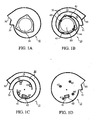
- FIGS. 1A and 1B show the top and bottom view, respectively, of a top waveguide member 10, while FIGS. 1C and 1D show the top and bottom view, respectively, of a matching bottom waveguide member 11.
- a spiral waveguide is formed by attaching a top waveguide member 10 with a bottom waveguide member 11, thus forming a waveguide channel 20 (with a length L) having an open end 30 and a closed end 31.
- the two waveguide members, 10 and 11 are attached by four screws through the four holes, 41, 42, 43 and 44.
- the two waveguide members may be attached by screws, bolts, nails, clips, tabs and slots, tongues and grooves, pins, g lue, adhesive, cement and the like.
- the top waveguide member 10 has a transducer opening 50, where an electroacoustical transducer such as a loudspeaker transducer (not shown) may be mounted.
- the bottom waveguide member 11 provides for two holes 61, 62 which provide a passage for wire connecting the transducer to an electrical signal source.
- the transducer opening 50 is located along the waveguide channel 20 such that it divides the wave guide channel 20 into two contiguous channels, an open-ended channel 21 (having a length L 1 ) and a closed-ended channel 22 (having a length L 2 ). Both of the contiguous channels 21, 22 have a smoothly changing curvature with radius, substantially identical rectangular cross sections, and are centered about the same spiral axis.
- the length of waveguide channel 20 plus any end effect is approximately one quarter of the wavelength of the lowest frequency pressure wave energy to be transmitted by the waveguide. For example, if the lowest frequency pressure wave energy to be transmitted by the waveguide is 60 Hz in air at room temperature, the length of the waveguide channel 20 (plus any end effect) is approximately 1.4 meters.
- the walls of the waveguide channel 20 are hard. PVC, ABS, Lexan, other hard plastic, metal, or wood materials or the like provide suitable material to construct the walls of the waveguide.
- the transducer may be mounted at any location along the waveguide channel 20 depending on the design of the system.
- the transducer opening 50 is configured to mount an electroacoustical transducer such that path length of the open -ended channel 21 is approximately twice as long as the closed-ended channel 22. This positioning of the transducer is useful for greatly reducing the first resonance peak that would be present in the frequency response of the acoustic energy transmitted by a single -ended waveguide.
- FIGS. 2A and 2B show a graphical representation of the acoustic power output as a function of frequency at the open end of a waveguide channel (FIG. 2A) and at the transducer opening (FIG. 2B) (i) with the transducer located adjacent to the closed end of the waveguide channel of length L and (ii) with the transducer located between the open end and the closed end such that the distance between the open end and the transducer is approximately twice as long (2/3L) as the distance between the closed end and the transducer (1/3L).
- the waveguide channel is approximately 1.34 meters in length, has a circular cross section with a cross-sectional diameter of 7.23 cm, and is approximately 56% of the cross-sectional area of the transducer.
- a volume located behind the transducer and between the transducer and waveguide channel is not necessary and is preferably as small as practical (ideally zero) if the mechanical dimensions of the transducer, the cross-sectional area of the waveguide and other design restrictions permit it. Removing or reducing the volume between the transducer and waveguide channel in this example would still leave the beneficial results described of a reduction in the first resonance peak.
- the first resonance peak which occurs at approximately 200 Hz in this example, is greatly reduced by positioning the transducer at a location that divides the waveguide channel into a closed end channel of length 1/3L and an open ended channel of length 2/3L (i.e., a 2:1 ratio).
- FIG. 2B shows that the transducer output does not experience a corresponding null (i.e, reduced displacement) at approximately 200 Hz.
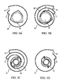
- FIGS. 3A-3E show another embodiment of a spiral waveguide electroacoustical transducing system.
- FIGS. 3A and 3B show the top and bottom view, respectively, of a top waveguide member 10, while FIGS. 3C and 3D show the top and bottom view, respectively, of a matching bottom waveguide member 11.
- FIG. 3E shows a side view of the assembled spiral waveguide electroacoustical transducing system.
- the waveguide shown in FIGS. 3A-3E is similar in structure to the waveguide shown in FIGS. 1A-1D, having a spiral-shaped waveguide channel 20 with an open end 30 and closed end 31.
- a transducer opening 50 is provided in the top waveguide member 10 and divides the waveguide channel 20 into an open -ended channel 21 and a contiguous closed-ended channel 22.
- the transducer opening is located along the waveguide channel 20 such that the open -ended channel 21 is approximately twice as long as the closed-ended channel 22.
- the dimension between the top and bottom surfaces of the assembled waveguide is reduced to make a more compact structure by allowing the rear of the transducer to protrude beyond said bottom surface.
- back housing 70 which may be formed as an integral part of the bottom wave guide member 11 or it may be formed as a separate structure to be affixed to the rear of the bottom waveguide member 11.
- the front side of the transducer faces out of the transducer opening 50.
- a volume located behind the transducer and between the transducer and waveguide is created. While from an acoustical performance standpoint, it is normally preferable to have a minimal volume behind the transducer and between the transducer and waveguide, other design considerations such as limitations in the amount of physical space available for the waveguide may necessitate a volume behind the transducer and between the transducer and the waveguide.
- FIGS. 1A-D and 3A-E illustrate a spiral waveguide assembly having two contiguous spiral channels, 21, 22, which radiate out from the transducer opening 50.
- another embodiment of the spiral waveguide may have a single spiral channel radiating out from an inner end to an outer end, with the electroacoustical transducer mounted adjacent to the inner end (thus forming a single-ended waveguide).
- the transducer may be mounted such that the vibratile surface of the transducer is parallel to the plane of the spiral waveguide channels as shown in FIGS.
- the spiral waveguide may also be formed as a flat spiral (as illustrated in FIGS. 1A-D and 3A-E) where the waveguide channel is coiled in a single plane, or the waveguide may be formed as a helical spiral (i.e., a helix) where the waveguide channel is coiled in a constantly changing plane.
- the cross section of the waveguide channel may be rectangular, circular, oval or the like.
- the length and cross section of the waveguide channels may be modified according to the lowest desired frequency of transmission, medium of transmission, and surface area of the vibratile surface of the transducer.
- the transducer does not have to be partially or fully enclosed by the waveguide structure with the front of said transducer facing out of the waveguide through hole 50, but may, for example, be mounted external to said waveguide structure such that the front of the transducer faces into the waveguide through hole 50.
- 1A-D and 3A-E show a two-piece construction of the waveguide channel, however, the two piece construction may consist of a single top or bottom member comprising the waveguide walls and a corresp onding bottom or top member which is substantially flat and which, when assembled with the top or bottom member, forms the fourth wall of the waveguide or construction of the waveguide channel may be of a single piece of construction or may be formed from multiple pieces attached together. Additional embodiments may include damping material, such as polyester, disposed within one or more of the waveguide channels.
Landscapes
- Health & Medical Sciences (AREA)
- Otolaryngology (AREA)
- Physics & Mathematics (AREA)
- Engineering & Computer Science (AREA)
- Acoustics & Sound (AREA)
- Signal Processing (AREA)
- Obtaining Desirable Characteristics In Audible-Bandwidth Transducers (AREA)
- Surface Acoustic Wave Elements And Circuit Networks Thereof (AREA)
- Apparatuses For Generation Of Mechanical Vibrations (AREA)
- Details Of Audible-Bandwidth Transducers (AREA)
Abstract
Description
Claims (22)
- An acoustic waveguide for transmitting pressure wave energy produced by an electroacoustical transducer in a medium that propagates press ure wave energy, the waveguide comprising:wherein a transducer opening for accommodating an electroacoustical transducer is adjacent to the first end of the tube and the second end of the tube is open to the medium.a tube having a first end and a second end and formed in a spiral configuration, wherein the tube defines a spiral-shaped channel with a length L; and
- The acoustic waveguide of claim 1 wherein the length of the channel L plus end effect is approximately one quarter of the wavelength of the lowest frequency pressure wave energy to be transmitted by the waveguide.
- An acoustic waveguide for transmitting pressure wave energy produced by an electroacoustical transducer in a medium that propagates pressure wave energy, the waveguide comprising:wherein the tube defines a first spiral -shaped channel located between the transducer opening of the tube and the first end of the tube and a contiguous second spiral-shaped channel located between the transducer opening of the tube and the second end of the tube; anda tube having a first end and a second end and formed in a spiral configuration, the tube having a transducer opening for accommodating an electroacoustical transducer between the first end and second end of the tube;
wherein the first end of the tube is closed and the second end of the tube is open to the medium. - The acoustic waveguide of claim 3, wherein the first spiral -shaped channel defined by the tube has a length of 1/3L and the second spiral -shaped channel has a length of 2/3L.
- The acoustic waveguide of any of the preceding claims, wherein the or each spiral-shaped channel has a smoothly changing curvature with radius.
- The acoustic waveguide of any of the preceding claims, wherein the inner walls of the tube are contiguous.
- The acoustic waveguide of claim 3, wherein the length of the first spiral-shaped channel, 1/3L, plus the length of the second spiral-shaped channel, 2/3L, is approximately one quarter of the wavelength of the lowest frequency pressure wave energy to be transmitted by the waveguide.
- The acoustic waveguide of claim 3, wherein the first spiral -shaped channel defined by the tube has substantially the same cross-section as the second spiral-shaped channel defined by the tube.
- The acoustic waveguide of any of the preceding claims, wherein the cross section of the or each spiral-shaped channel is rectangular.
- The acoustic waveguide of any of the preceding claims, wherein the tube is composed of rigid plastic.
- The acoustic waveguide of any of the preceding claims, wherein the tube is coiled in a single plane, forming a flat spiral.
- The acoustic waveguide of any of claims 1 to 11, wherein the tube is coiled in a plurality of planes, forming a helical spiral.
- The acoustic waveguide of claim 3, further comprising:wherein the tube has a second electroacoustical transducer opening located between the tube and the transducer housing.a transducer housing attached to the tube; and
- The acoustic waveguide of claim 3, wherein the tube comprises:wherein the bottom surface of the upper tube member is attached to the top surface of the lower tube member such that the first and second grooves of each member align to form the first spiral-shaped channel and the second spiral-shaped channel.an upper tube member having a top surface and a bottom surface, the top surface having the transducer opening and the bottom surface having a first spiral-shaped groove defining the upper portion of the first spiral -shaped channel located between the transducer opening and the first end of the tube, the bottom surface also having a second spiral-shaped groove contiguous to the first spiral-shaped groove and defining an upper portion of the second spiral -shaped channel located between the transducer opening and the second end of the tube; anda lower tube member having a top surface and a bottom surface, the top surface having a first spiral-shaped groove defining the lower portion of the first spiral-shaped channel located between the transducer opening and the first end of the tube, the top surface also having a second spiral-shaped groove contiguous to the first spiral-shaped groove and defining a lower portion of the second spiral-shaped channel located between the transducer opening and the second end of the tube;
- The acoustic waveguide of claim 14, further comprising:wherein the bottom surface of the lower tube member has a second transducer opening located between the tube and the transducer housing.a transducer housing attached to the tube; and
- The acoustic waveguide of claim 14, wherein the upper tube member is attached to the lower tube member with screws.
- The acoustic waveguide of claim 14, wherein the upper tube member is attached to the lower tube member with adhesive.
- An acoustic waveguide in accordance with claim 1 or claim 8, wherein said waveguide comprises a first assembly forming three waveguide walls and a second assembly that is a substantially flat plate comprising a fourth waveguide wall closing the waveguide.
- A system for transmitting pressure wave energy in a medium that propagates pressure wave energy in a medium, the system comprising:an electroacoustical transducer having a vibratile surface; anda spiral waveguide according to any of the preceding claims.
- A method of making a spiral -shaped waveguide comprising:forming a first member having a top surface and a bottom surface, the top surface of the first member having a transducer opening, the bottom surface of th e first member having at least one spiral-shaped tube;forming a second member having a top surface and a bottom surface, the top surface having at least one spiral-shaped groove that is the mirror image of the spiral-shaped groove provided on the bottom surface of the first member;attaching the bottom surface of the first member and the top surface of the second member such that the groove provided in the bottom surface of the first member aligns with the groove provided in the top surface of the second member, thereby forming a spiral shaped channel.
- The method of claim 20, wherein the bottom surface of the first member and the top surface of the second member are attached with screws.
- The method of claim 20, wherein the bottom surface of the first member and the top surface of the second member are attached with adhesive.
Applications Claiming Priority (4)
| Application Number | Priority Date | Filing Date | Title |
|---|---|---|---|
| US7278402A | 2002-02-08 | 2002-02-08 | |
| US72784 | 2002-02-08 | ||
| US10/085,382 US6648098B2 (en) | 2002-02-08 | 2002-02-28 | Spiral acoustic waveguide electroacoustical transducing system |
| US85382 | 2002-02-28 |
Publications (3)
| Publication Number | Publication Date |
|---|---|
| EP1335629A2 true EP1335629A2 (en) | 2003-08-13 |
| EP1335629A3 EP1335629A3 (en) | 2005-02-09 |
| EP1335629B1 EP1335629B1 (en) | 2009-03-25 |
Family
ID=27616013
Family Applications (1)
| Application Number | Title | Priority Date | Filing Date |
|---|---|---|---|
| EP03100041A Expired - Lifetime EP1335629B1 (en) | 2002-02-08 | 2003-01-13 | Spiral acoustic waveguide electroacoustical transducing system |
Country Status (4)
| Country | Link |
|---|---|
| US (1) | US6648098B2 (en) |
| EP (1) | EP1335629B1 (en) |
| JP (1) | JP2003264887A (en) |
| CN (1) | CN100490561C (en) |
Cited By (1)
| Publication number | Priority date | Publication date | Assignee | Title |
|---|---|---|---|---|
| WO2014165359A1 (en) * | 2013-04-01 | 2014-10-09 | Colorado Energy Research Technologies, LLC | Phi-based enclosure for speaker systems |
Families Citing this family (31)
| Publication number | Priority date | Publication date | Assignee | Title |
|---|---|---|---|---|
| FI112909B (en) * | 2001-02-19 | 2004-01-30 | Genelec Oy | Reflector speaker construction and method for providing the same |
| JP2005167315A (en) * | 2003-11-28 | 2005-06-23 | Pioneer Electronic Corp | Speaker unit |
| TWI254588B (en) * | 2004-03-18 | 2006-05-01 | Cotron Corp | Speaker module frame, speaker module therewith, and electrical device with the speaker module |
| US7565948B2 (en) * | 2004-03-19 | 2009-07-28 | Bose Corporation | Acoustic waveguiding |
| US7584820B2 (en) * | 2004-03-19 | 2009-09-08 | Bose Corporation | Acoustic radiating |
| US7549509B2 (en) * | 2005-04-21 | 2009-06-23 | Ingersoll-Rand Company | Double throat pulsation dampener for a compressor |
| US20080212807A1 (en) * | 2005-06-08 | 2008-09-04 | General Mems Corporation | Micromachined Acoustic Transducers |
| US7284638B1 (en) * | 2006-05-08 | 2007-10-23 | Sahyoun Joseph Y | Loudspeaker low profile quarter wavelength transmission line and enclosure and method |
| KR100782482B1 (en) * | 2006-05-19 | 2007-12-05 | 삼성전자주식회사 | A phase change memory cell employing a thin film as a phase change material film, a phase change memory device having the same, an electronic device having the same, and a manufacturing method thereof |
| US7617794B2 (en) * | 2007-03-30 | 2009-11-17 | Nissan Technical Center North America, Inc. | One piece horn cover |
| WO2009055373A1 (en) | 2007-10-22 | 2009-04-30 | David Maeshiba | Acoustic system |
| RU2388175C2 (en) * | 2007-12-19 | 2010-04-27 | Сергей Георгиевич Касоев | Helix directional microphone |
| CN102870437B (en) * | 2010-05-03 | 2015-09-16 | 安赫尔·胡利奥·莫尔顿·塞斯特罗斯 | Loudspeaker enclosure |
| RU2494570C1 (en) * | 2012-02-01 | 2013-09-27 | Федеральное государственное образовательное бюджетное учреждение высшего профессионального образования Московский технический университет связи и информатики (ФГОБУ ВПО МТУСИ) | Method for highly directional reception of sound waves |
| ES2622370T3 (en) * | 2012-06-07 | 2017-07-06 | Jda Technology Llc | Wrapped bass-reflex audio speakers |
| US9179220B2 (en) | 2012-07-10 | 2015-11-03 | Google Inc. | Life safety device with folded resonant cavity for low frequency alarm tones |
| US20150382103A1 (en) * | 2013-04-01 | 2015-12-31 | Colorado Energy Research Technologies, LLC | Phi-Based Enclosure for Speaker Systems |
| US8810426B1 (en) | 2013-04-28 | 2014-08-19 | Gary Jay Morris | Life safety device with compact circumferential acoustic resonator |
| JP6251881B2 (en) * | 2013-07-24 | 2017-12-27 | パナソニックIpマネジメント株式会社 | SPEAKER SYSTEM, ELECTRONIC DEVICE USING THE SAME, AND MOBILE DEVICE |
| JP6593741B2 (en) * | 2014-04-30 | 2019-10-23 | パナソニックIpマネジメント株式会社 | Speaker system |
| WO2016162880A1 (en) | 2015-04-10 | 2016-10-13 | Indian Institute Of Technology Madras | A novel ultrasonic waveguide technique for distributed sensing and measurements of physical and chemical properties of surrounding media |
| US10504499B2 (en) * | 2015-08-12 | 2019-12-10 | George A. Economou | Extracting features from auditory observations with active or passive assistance of shape-based auditory modification apparatus |
| JP2019515590A (en) * | 2016-05-10 | 2019-06-06 | ボーズ・コーポレーションBose Corporation | Sound equipment |
| US10397681B2 (en) * | 2016-12-11 | 2019-08-27 | Base Corporation | Acoustic transducer |
| EP3593542A1 (en) * | 2017-03-08 | 2020-01-15 | King Abdullah University Of Science And Technology | Audio speaker and method of producing an audio speaker |
| CN107331381A (en) * | 2017-05-12 | 2017-11-07 | 南京大学 | A kind of broadband acoustics coupler |
| DE202017005756U1 (en) | 2017-10-25 | 2018-01-17 | Johann Ablinger | Screw Speaker |
| US11317178B2 (en) * | 2019-07-12 | 2022-04-26 | Clay Allison | Low-frequency spiral waveguide speaker |
| US10950212B1 (en) * | 2020-02-25 | 2021-03-16 | Acoustic Metamaterials LLC | Acoustic meta material passive spiral audio amplifier and a method to make the same |
| US11881204B2 (en) * | 2020-07-30 | 2024-01-23 | Ford Global Technologies, Llc | Dual-tone horn assemblies and methods of use |
| JP6952386B1 (en) * | 2021-04-06 | 2021-10-20 | 有限会社サワキ | Vehicle speaker device and room speaker device |
Family Cites Families (11)
| Publication number | Priority date | Publication date | Assignee | Title |
|---|---|---|---|---|
| US1890719A (en) * | 1928-07-05 | 1932-12-13 | Vern W Busch | Horn |
| US1888769A (en) * | 1929-01-16 | 1932-11-22 | Muench Walter | Loud-speaker |
| US3687221A (en) * | 1971-03-08 | 1972-08-29 | Michel Paul Rene Bonnard | Sound reproduction acoustic enclosure |
| US4628528A (en) | 1982-09-29 | 1986-12-09 | Bose Corporation | Pressure wave transducing |
| JPS6372297A (en) * | 1986-09-12 | 1988-04-01 | Matsushita Electric Ind Co Ltd | Speaker system |
| US6278789B1 (en) * | 1993-05-06 | 2001-08-21 | Bose Corporation | Frequency selective acoustic waveguide damping |
| US5751827A (en) * | 1995-03-13 | 1998-05-12 | Primo Microphones, Inc. | Piezoelectric speaker |
| US5824969A (en) * | 1996-09-30 | 1998-10-20 | Takenaka; Masaaki | Speaker system with a three-dimensional spiral sound passage |
| JP3911754B2 (en) * | 1997-02-21 | 2007-05-09 | 松下電器産業株式会社 | Speaker device |
| US5975236A (en) * | 1998-01-08 | 1999-11-02 | Yamamoto; Shuji | Speaker assembly |
| JPH11220789A (en) * | 1998-01-30 | 1999-08-10 | Sony Corp | Electroacoustic transducer |
-
2002
- 2002-02-28 US US10/085,382 patent/US6648098B2/en not_active Expired - Lifetime
-
2003
- 2003-01-13 EP EP03100041A patent/EP1335629B1/en not_active Expired - Lifetime
- 2003-01-31 CN CNB031031811A patent/CN100490561C/en not_active Expired - Fee Related
- 2003-02-07 JP JP2003031186A patent/JP2003264887A/en active Pending
Cited By (2)
| Publication number | Priority date | Publication date | Assignee | Title |
|---|---|---|---|---|
| WO2014165359A1 (en) * | 2013-04-01 | 2014-10-09 | Colorado Energy Research Technologies, LLC | Phi-based enclosure for speaker systems |
| US9161119B2 (en) | 2013-04-01 | 2015-10-13 | Colorado Energy Research Technologies, LLC | Phi-based enclosure for speaker systems |
Also Published As
| Publication number | Publication date |
|---|---|
| EP1335629B1 (en) | 2009-03-25 |
| US20030150668A1 (en) | 2003-08-14 |
| CN1438816A (en) | 2003-08-27 |
| US6648098B2 (en) | 2003-11-18 |
| CN100490561C (en) | 2009-05-20 |
| JP2003264887A (en) | 2003-09-19 |
| EP1335629A3 (en) | 2005-02-09 |
Similar Documents
| Publication | Publication Date | Title |
|---|---|---|
| EP1335629B1 (en) | Spiral acoustic waveguide electroacoustical transducing system | |
| EP0219529B1 (en) | Speaker adapted to corner-loaded installation | |
| US5637840A (en) | Miniaturized high power speaker | |
| US5197103A (en) | Low sound loudspeaker system | |
| US5170435A (en) | Waveguide electroacoustical transducing | |
| US5261006A (en) | Loudspeaker system comprising a helmholtz resonator coupled to an acoustic tube | |
| US6516076B1 (en) | Modular horn loudspeaker | |
| US4553628A (en) | Speaker system | |
| US7748495B2 (en) | Tubular loudspeaker | |
| US5590208A (en) | Speaker system | |
| CN101031222A (en) | Closed loop embedded audio transmission line technology | |
| AU2013271505B2 (en) | Ported audio speaker enclosures | |
| CN1670819B (en) | Acoustic waveguiding | |
| GB2258365A (en) | Speaker system with opposed drive units | |
| US6513624B2 (en) | Loudspeaker enclosure | |
| US20060078136A1 (en) | Chamber-loaded augmented passive radiator | |
| US4807293A (en) | Loudspeaker housing | |
| US6681023B1 (en) | Radial pickup microphone enclosure | |
| US20060078144A1 (en) | Compound-driven augmented passive radiator | |
| CN116491128A (en) | audio device | |
| US6307947B1 (en) | Low profile speaker enclosure | |
| CN108781315A (en) | Loudspeaker module with disparate modules shell geometry and similar acoustic characteristic | |
| US11601748B1 (en) | Techniques for loudspeaker | |
| CN113015069B (en) | Compression Driver | |
| CN220915404U (en) | Waveguide and horn, loudspeaker box, array and multistage array comprising same |
Legal Events
| Date | Code | Title | Description |
|---|---|---|---|
| PUAI | Public reference made under article 153(3) epc to a published international application that has entered the european phase |
Free format text: ORIGINAL CODE: 0009012 |
|
| AK | Designated contracting states |
Designated state(s): AT BE BG CH CY CZ DE DK EE ES FI FR GB GR HU IE IT LI LU MC NL PT SE SI SK TR |
|
| AX | Request for extension of the european patent |
Extension state: AL LT LV MK RO |
|
| RIC1 | Information provided on ipc code assigned before grant |
Ipc: 7H 04R 1/28 B Ipc: 7H 04R 1/34 A |
|
| PUAL | Search report despatched |
Free format text: ORIGINAL CODE: 0009013 |
|
| RIC1 | Information provided on ipc code assigned before grant |
Ipc: 7H 04R 1/28 B Ipc: 7G 10K 11/02 B Ipc: 7H 04R 1/34 A Ipc: 7H 04R 17/00 B |
|
| AK | Designated contracting states |
Kind code of ref document: A3 Designated state(s): AT BE BG CH CY CZ DE DK EE ES FI FR GB GR HU IE IT LI LU MC NL PT SE SI SK TR |
|
| AX | Request for extension of the european patent |
Extension state: AL LT LV MK RO |
|
| 17P | Request for examination filed |
Effective date: 20050728 |
|
| AKX | Designation fees paid |
Designated state(s): DE FR |
|
| GRAP | Despatch of communication of intention to grant a patent |
Free format text: ORIGINAL CODE: EPIDOSNIGR1 |
|
| GRAS | Grant fee paid |
Free format text: ORIGINAL CODE: EPIDOSNIGR3 |
|
| GRAA | (expected) grant |
Free format text: ORIGINAL CODE: 0009210 |
|
| RBV | Designated contracting states (corrected) |
Designated state(s): DE GB |
|
| AK | Designated contracting states |
Kind code of ref document: B1 Designated state(s): DE GB |
|
| REG | Reference to a national code |
Ref country code: GB Ref legal event code: FG4D |
|
| REF | Corresponds to: |
Ref document number: 60326786 Country of ref document: DE Date of ref document: 20090507 Kind code of ref document: P |
|
| PLBE | No opposition filed within time limit |
Free format text: ORIGINAL CODE: 0009261 |
|
| STAA | Information on the status of an ep patent application or granted ep patent |
Free format text: STATUS: NO OPPOSITION FILED WITHIN TIME LIMIT |
|
| 26N | No opposition filed |
Effective date: 20091229 |
|
| PGFP | Annual fee paid to national office [announced via postgrant information from national office to epo] |
Ref country code: DE Payment date: 20150128 Year of fee payment: 13 |
|
| PGFP | Annual fee paid to national office [announced via postgrant information from national office to epo] |
Ref country code: GB Payment date: 20150127 Year of fee payment: 13 |
|
| REG | Reference to a national code |
Ref country code: DE Ref legal event code: R119 Ref document number: 60326786 Country of ref document: DE |
|
| GBPC | Gb: european patent ceased through non-payment of renewal fee |
Effective date: 20160113 |
|
| PG25 | Lapsed in a contracting state [announced via postgrant information from national office to epo] |
Ref country code: GB Free format text: LAPSE BECAUSE OF NON-PAYMENT OF DUE FEES Effective date: 20160113 Ref country code: DE Free format text: LAPSE BECAUSE OF NON-PAYMENT OF DUE FEES Effective date: 20160802 |