EP1335539A1 - Method, terminal and router for detection of trigger to rerouting - Google Patents
Method, terminal and router for detection of trigger to rerouting Download PDFInfo
- Publication number
- EP1335539A1 EP1335539A1 EP20030001372 EP03001372A EP1335539A1 EP 1335539 A1 EP1335539 A1 EP 1335539A1 EP 20030001372 EP20030001372 EP 20030001372 EP 03001372 A EP03001372 A EP 03001372A EP 1335539 A1 EP1335539 A1 EP 1335539A1
- Authority
- EP
- European Patent Office
- Prior art keywords
- hops
- terminal
- data
- routing
- acquired
- Prior art date
- Legal status (The legal status is an assumption and is not a legal conclusion. Google has not performed a legal analysis and makes no representation as to the accuracy of the status listed.)
- Withdrawn
Links
Images


Classifications
-
- H—ELECTRICITY
- H04—ELECTRIC COMMUNICATION TECHNIQUE
- H04W—WIRELESS COMMUNICATION NETWORKS
- H04W40/00—Communication routing or communication path finding
- H04W40/34—Modification of an existing route
- H04W40/36—Modification of an existing route due to handover
-
- H—ELECTRICITY
- H04—ELECTRIC COMMUNICATION TECHNIQUE
- H04L—TRANSMISSION OF DIGITAL INFORMATION, e.g. TELEGRAPHIC COMMUNICATION
- H04L45/00—Routing or path finding of packets in data switching networks
- H04L45/12—Shortest path evaluation
- H04L45/122—Shortest path evaluation by minimising distances, e.g. by selecting a route with minimum of number of hops
-
- H—ELECTRICITY
- H04—ELECTRIC COMMUNICATION TECHNIQUE
- H04L—TRANSMISSION OF DIGITAL INFORMATION, e.g. TELEGRAPHIC COMMUNICATION
- H04L45/00—Routing or path finding of packets in data switching networks
- H04L45/20—Hop count for routing purposes, e.g. TTL
-
- H—ELECTRICITY
- H04—ELECTRIC COMMUNICATION TECHNIQUE
- H04W—WIRELESS COMMUNICATION NETWORKS
- H04W36/00—Hand-off or reselection arrangements
- H04W36/12—Reselecting a serving backbone network switching or routing node
-
- H—ELECTRICITY
- H04—ELECTRIC COMMUNICATION TECHNIQUE
- H04W—WIRELESS COMMUNICATION NETWORKS
- H04W84/00—Network topologies
- H04W84/02—Hierarchically pre-organised networks, e.g. paging networks, cellular networks, WLAN [Wireless Local Area Network] or WLL [Wireless Local Loop]
- H04W84/04—Large scale networks; Deep hierarchical networks
Definitions
- the present invention relates to a method, a terminal and a router for detecting a trigger to rerouting, and more particularly to a method, a terminal and a router for detecting a trigger to rerouting for controlling an alteration of redundant routing.
- GPRS packet exchange control system
- 3GPP 3rd Generation Partnership Project
- This rerouting control is performed when the mobile terminal moves from one RNC to another (inter-RNC handover), but this rerouting control is not performed when the mobile terminal moves from one base transceiver station (BTS) to another in the territory of the same RNC (intra-RNC handover).
- BTS base transceiver station
- intra-RNC handover the route from the RNC to the BTS can be switched by soft handover, but that at a higher level than the RNC (between the RNC and the GGSN) cannot be switched.
- optimal rerouting can be accomplished if the radio channel is a common channel, but if it is a common channel, the subscriber line extension entails the occurrence of a redundant portion on the route, resulting in wasteful use of network resources.
- SRNS relocation is permitted under the 3GPP standard specifications even when operating on a dedicated channel
- SRNS relocation is a technique that is made feasible by the capability of the network to keep track of whether a mobile terminal has moved from one RNC to another.
- IP network As there are many different topologies including a mesh structure and a tree structure or the like and the structure can usually be altered as desired, it is not realistic for the network to manage the structure, and it is impossible to apply the 3GPP specifications as they are.
- FIGS. 7 illustrate how the conventional system works, namely how routing is altered where a mobile communication terminal M under GPRS shifts its position.
- FIG. 7A shows a case in which the radio channel between the mobile communication terminal M and the base transceiver station is a common channel
- FIG. 7B a case in which the radio channel between the mobile communication terminal M and the base transceiver station is a dedicated channel.
- a GGSN 1 in FIG. 7A is a gateway GPRS support node, positioned at the gateway to the network where there is a server or a terminal which is to become a communication partner 8 with the mobile communication terminal M. Communication between the mobile communication terminal M and the communication partner 8 takes place via this GGSN 1.
- An SGSN 2 is a Serving GPRS Support Node (SGSN), which is connected to the GGSN 1 and is the switchboard nearest to the mobile communication terminal M.
- An RNC 3 is a radio network controller having functions to control radio resources and to control the handover when the mobile communication terminal M has shifted its position.
- BTSs 41 to 44 are base transceiver stations, and the mobile terminal carries out communication through connection to one or another of these BTSs.
- the radio channel between the mobile communication terminal M and the base transceiver station is a common channel as shown in FIG. 7A
- the communication path between the mobile communication terminal M and its communication partner 8 is switched from a route R1 to a route R2, which is the shortest cut, with the GGSN 1 as the starting point along with a shift, represented by an arrow Y3, of the mobile communication terminal M.
- the radio channel is a dedicated channel as shown in FIG. 7B
- subscriber line extension takes place whereby, starting from an RNC 31 which was on the communication path when communication was begun, a route R3 is extended toward an RNC 32 and a BTS43, which are the destinations of the shift, in the direction represented by an arrow Y4, of the mobile communication terminal M (a route R4).
- This system is used to restrain any data loss that may arise when the communication path is switched by a handover, but a more redundant route shown in FIG. 7B will arise, compared with the optimal (shortest) route (the route R2 in FIG. 7A).
- the rerouting method is selected solely dependent on the state of the radio channel, resulting in a disadvantage that routing cannot be optimized on a real time basis in response to a handover of the mobile communication terminal M.
- this problem could be addressed by either (1) invoking the procedure of change-over to the optimal route upon every handover of the mobile terminal or (2) invoking the same upon an inter-RNC handover.
- the method of (1) may invoke a wasteful procedure because an intra-RNC handover would need no optimization of routing (the handover would give rise to no redundant route).
- the method of (2) is unrealistic because managing the structure of a usual IP network, such as the one mentioned above, is difficult to manage and accordingly it is difficult to determine whether or not a given RNC is an "inter-RNC".
- An object of the present invention is to provide a method, a terminal and a router for detecting a trigger to rerouting for providing on a real time basis a trigger to anchor router (hereinafter abbreviated to "AncR") reselection by constantly comparing during communication the number of hops required for the routing of a data packet from the communication partner of a mobile terminal to the mobile terminal.
- AncR trigger to anchor router
- a method of detecting a trigger to rerouting is provided which is characterized by including a comparative step of comparing the respective numbers of hops arising at terminals in data transmission and reception arising between the terminals, and an optimizing step of achieving optimization, if the result of comparison at the comparative step indicates that the number of hops in later data transmission and reception is greater, by altering the routing so as to reduce the number of hops.
- any redundancy on the route can be detected according to an increase in the number of hops, and the route can be optimized on that basis.
- Routing in the transmission and reception of the data may be accomplished with at least one of a plurality of routers relaying the data serves as the anchor, if the number of hops in later data transmission and reception is found greater as the result of comparison at the comparative step, the router to serve as this anchor (anchor router) is altered at the optimizing step.
- the numbers of hops between transmission terminal transmitting data and reception terminal receiving the data may be compared at the comparative step, and the routing may be altered at the optimizing step according to the result of comparison at the comparative step.
- the optimal rerouting can be accomplished without having to grasp the overall situation of the communication network including the identification of the source of redundancy as the shift of the own terminal or that of the other party to the terminal or any other factor.
- the number of hops of the currently received data at the reception terminal and the number of hops of the immediately preceding received data at the reception terminal may be compared at the comparative step, and routing may be altered at the optimizing step so as to reduce the number of hops if the result of comparison at the comparative step reveals that the number of hops of the currently received data is greater than the number of hops of the immediately preceding received data.
- the optimal rerouting can be accomplished on a substantially real time basis while the mobile terminal is engaged in communication.
- the number of hops may be acquired by acquiring on the basis of parameters in data, the parameters being modified by routers which are passed between the transmission terminal and the reception terminal during the time they communicate, the variances between the values of the parameters at the starting point of counting and the values of the parameters at the ending point of counting, and identifying the number of routers corresponding to those variances.
- the parameters may be initialized at the starting point, and the variances can be acquired on the basis of the resultant initial values.
- a terminal includes an acquiring unit which acquires the number of hops and an issuing unit which issues, if the number of hops currently acquired by the acquiring unit is greater than the number of hops acquired in the past, an optimizing instruction to alter routing to the other terminal to reduce the number of hops and optimize it, it being so arranged that an external apparatus having received the instruction optimizes the inter-terminal routing.
- a router includes an acquiring unit which acquires the number of hops and an issuing unit which issues, if the number of hops currently acquired by the acquiring unit is greater than the number of hops acquired in the past, an optimizing instruction to alter the inter-terminal routing to reduce the number of hops and optimize it, it being so arranged that an external apparatus having received the instruction optimizes the inter-terminal routing.
- the router may further include a receiver unit which receives the number of hops acquired by another apparatus in the past, wherein the issuing unit issues, if the number of hops currently acquired by the acquiring unit is greater than the past number of hops acquired by the receiver unit, an optimizing instruction to alter the inter-terminal routing to reduce and optimize it, and an external apparatus having received the instruction optimizes the inter-terminal routing.
- the router may further include a transmitter unit which transmits the number of hops acquired by the acquiring unit to an external comparator which detects any increase in the number of hops in the inter-terminal communication on the basis of the acquired number of hops.
- the router may also include an initializing unit which initializes parameters in data modified by a router installed between the terminals for the communication of data to identify the number of hops, wherein the variances of said parameters matching said number of hops can be acquired on the basis of the resultant initialized values.
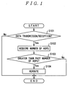
- FIG. 1 is a flow chart of a method of detecting a trigger to rerouting.
- FIG. 2 illustrates how routing takes place if the method of detecting a trigger to rerouting is applied to a case in which a correspondent node (CN) is in another network.
- CN correspondent node
- FIG. 3 illustrates how routing takes place if the method of detecting a trigger to rerouting is applied to a case in which a CN is in the own network.
- FIG. 4 is a block diagram of the configuration of a terminal for use in an implementation of this method.
- FIG. 5A is a block diagram of a configuration of an access router for use in the implementation of this method
- FIG. 5B a block diagram of a configuration of an access router for transmitting the number of hops to an access router at the destination of shifting
- FIG. 5C a block diagram of a configuration of an access router for receiving the number of hops from an access router in the position before the shift.
- FIG. 6 is a block diagram of a configuration of a router for use in the implementation of this method.
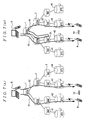
- FIG. 7A illustrates how routing takes place if a radio channel between a mobile communication terminal and a base transceiver station is a common channel in a conventional GPRS system
- FIG. 7B how routing takes place if the radio channel between the mobile communication terminal and the base transceiver station is a dedicated channel in the conventional GPRS system.
- step S101 transmission and reception of data between specific terminals is monitored.
- step S102 if transmission and reception of any data was detected at step S101, the number of routers the data have passed from the time they were transmitted from one terminal by the time they are received by another terminal, which is the communication partner, i.e. the number of hops, is acquired.
- step S103 the number of hops acquired at step S102 is compared with the number of hops acquired by earlier transmission and reception of data than at step S101. If this comparison reveals a greater number of hops at step S102, i.e. that the shift of the communicating terminal in the meantime has made the routing redundant, the process goes ahead to step S104.
- step S104 rerouting is carried out so as to reduce the number of hops.
- FIG. 2 illustrates how routing takes place if the method of detecting a trigger to rerouting according to the invention is applied to a case in which a correspondent node (CN), with which a mobile terminal communicates, is in another network (hereinafter referred to as the other network) than the network to which the mobile terminal belongs (hereinafter referred to as the own network).
- CN correspondent node
- the own network the network to which the mobile terminal belongs
- a CN 8 in this case may be a mobile terminal connected to the other network or any other terminal or a server.
- AncRs 51 and 52 are routers present on the route between the mobile communication terminal M and the CN 8, and communication takes place via them.
- the AncR 51 in Embodiment 1 usually is likely to be a router present on the boundary between the own network and the other network.
- the AncR 51 further has a function to capsulate a data packet destined from the CN 8 for the mobile communication terminal M when it passes and to transmit it to the mobile communication terminal M and a function to set in that data packet the initial number of hops in the form of combining consciousness with an access router (AR).
- RTs 61 and 62 are usual routers (RTs) present in the network.
- ARs 71 through 74 are routers present at one end or another of the network, and the mobile communication terminal M connects with the AR 72 among them and engages in wireless communication with the AR 72.
- FIG. 2 shows a situation in which the mobile communication terminal M is already connected to the AR 72 before a handover.
- the routing of a data packet from the CN 8 to the mobile communication terminal M then consists of a route R5 via the AncR 52.
- the data packet from the CN 8 is capsulated by the AncR 52, and the number of hops is initialized and transmitted to the mobile communication terminal M.
- the AR 72 detects from the received data packet (destined for the mobile terminal) the number of hops required between the CN 8 and the AR 72 on the basis of the initial number of hops set by the AncR 52, and stores that number.
- the AR 73 compares the number of hops between the CN 8 and the AR 72 at the AR 72 via the route R5, succeeded from the AR 72, with the number of hops between the CN 8 and the AR 73 detected when on the route R6, and detects an increase in the number of hops.
- the AR 73 invokes control to optimize the route, i.e. to reselect an AncR.
- control to select the AncR 51 as the relay node is invoked.
- AncR reselection control including direct notification by the AR 73 to the CN 8 that the subsequent communication will take place via the AncR 51, and a request by the AR 73 to the AncR, another router or mobile terminal to notify the CN 8 of the reselection.
- the routing is changed to the route R7 having the AncR 51 as its relay node, resulting in a switch to the optimal route.
- Various specific means are conceivable for handing over the data of the number of hops from the AR 72 to the AR 73 in this embodiment, including direct transmission of the data from the AR 72 to the AR 73, transmission of the data via another node (router) in the network, and transmission of the data via the pertinent mobile terminal.
- FIG. 3 illustrates how routing takes place if the present invention is applied to a case in which a CN is in the own network.
- the AR 75 detects the redundancy of routing by comparing the number of hops obtained from the reception data from the CN 8, and invokes control to optimize the route (reselect an AncR). Since the optimal AncR then is the RT 62, the control to change the AncR to the RT 62 is invoked.
- Specific parameters to be used in calculating the number of hops according to the invention include, for instance, a Time To Live (TTL) in IPv4 and a hop limit parameter in IPv6.
- TTL Time To Live
- IPv6 hop limit parameter
- a mobile communication terminal can also have the same functions and operations as the AR except the AR before the mobile communication terminal shifts to hand over the received number of hops that has been acquired to the AR to which the shift was desired for and the AR to which after the mobile communication terminal shifts to receive and store the number of hops received before the shift.
- the object of the invention is also attained when the mobile communication terminal acquires the number of hops, compares the currently acquired number of hops with the number of hops acquired in the past and issues an instruction to change the routing to another terminal is changed when the comparison reveals the current number of hops to be greater than the past number of hops.
- the terminal can be configured as shown in FIG. 4, or the access router configured as shown in FIG. 5 (A to C), and the router configured as shown in FIG. 6.
- the terminal M comprises a number of hops acquiring unit M1 and a command issuing unit M2.
- the number of hops acquiring unit M1 acquires, every time it receives data as indicated by an arrow Y6, the number of hops needed for the reception of the data.
- the command issuing unit M2 issues an instruction to change the routing to another terminal is changed when the number of hops received by the number of hops acquiring unit M1 proves greater than the number of hops acquired in the past.
- an access router 7 may comprise a number of hops acquiring unit 7A, a transmitter unit 7B, a command issuing unit 7C and a receiver unit 7D as shown in FIG. 5A.
- the number of hops acquiring unit 7A has similar functions to those of the number of hops acquiring unit provided on the terminal.
- the receiver unit 7D receives the number of hops transmitted from another access router 7.
- the transmitter unit 7B transmits, when the terminal under the command of the access router shifts as described above, the number of hops acquired in data communication immediately before the shift, to the other access router 7 which is to compare the number of hops.
- the command issuing unit 7C compares the number of hops acquired by the number of hops acquiring unit 7A or received by the receiver unit 7D, and issues an instruction to on the basis of the result of comparison as described above.
- FIG. 5B illustrates the minimum configuration the access router 7 requires when a terminal under its command has shift, and FIG. 5C, that the access router 7 requires when a terminal has been newly connected under its command.
- the access router 7 a terminal under whose command has moved out transmits the number of hops acquired by the number of hops acquiring unit 7A through the transmitter unit 7B.
- the access router 7 under whose command a terminal has been newly connected receives through the receiver unit 7D the number of hops before the shift, transmitted by that access router 7, i.e. the past number of hop, acquires the current number of hops through the number of hops acquiring unit 7A, and compares the current and past numbers of hops using the command issuing unit 7C.
- an access router 7 of a configuration shown in FIG. 5A is installed in the network.
- a router 9 includes an initializing unit 9A for setting initial values for parameters in data modified by a router installed between terminals engaged in communication of data to identify the number of hops. These parameters are the hop limit parameter and others as mentioned above. By initializing the number of hops at the router 9, especially the anchor router where the counting starts, having the access router or the like to acquire that parameter perceive the initial value, and acquiring the number of hops on the basis of the variance from the initial value, the number of hops can be acquired accurately.
- an AR or a mobile terminal detects the number of hops from data received in communication and stores it, compares it with the number of hops in new received data and thereby provides a trigger to reselection according to the present invention, eventually it can switch to the optimal route on a substantially real time basis while the mobile terminal is engaged in communication. Furthermore, as the invention can be applied irrespective of whether the communication partner is in another network or in the own network, and as it allows the detection of any redundancy in routing irrespective of the cause of redundancy, whether it is due to the shift of the own terminal, that of the communication partner or to any other factor, the resources in the network can be utilized more effectively by eliminating redundant routing.
Landscapes
- Engineering & Computer Science (AREA)
- Computer Networks & Wireless Communication (AREA)
- Signal Processing (AREA)
- Data Exchanges In Wide-Area Networks (AREA)
- Mobile Radio Communication Systems (AREA)
Abstract
Rerouting of packet exchanges by a mobile terminal is controlled so as
to be optimized on a real time basis to prevent network resources from being
wasted by redundant routing. In an initial state a route of data from a mobile
communication terminal M to a correspondent node CN 8, which is a communication partner, is a
route R5. Then, an access router (AR) 72 acquires the number of hops of
data received from the CN 8 by the mobile communication terminal M. As
the mobile communication terminal M now performs a handover under the
command of the AR 73, the route will change to a route R6. Then the AR 73
detects that the route becomes redundant by the fact that the number of hops
acquired after the shift is greater than the pre-shift number of hops received
from the AR 72, and invokes control to reroute to a route R7, which provides
the optimal routing.
Description
- The present invention relates to a method, a terminal and a router for detecting a trigger to rerouting, and more particularly to a method, a terminal and a router for detecting a trigger to rerouting for controlling an alteration of redundant routing.
- In the conventional packet exchange control system (GPRS) standardized under the 3rd Generation Partnership Project (3GPP), a manner of controlling the rerouting of a communicating mobile terminal when it has moved is differentiated with the type of radio channel between the mobile terminal and the base transceiver station during call. That is, available radio channels between the mobile terminal and the base transceiver station are classified into "dedicated channels" on which the volume of communication traffic is heavy and "common channels" on which the traffic volume is light. On the dedicated channel, the radio network controller (RNC) used at the time of initial establishment of communication is used as the anchor. And control to extend the route of data from the anchor (subscriber line extension) is performed. On the common channel, the Gateway GPRS Support Node (GGSN) is used as the anchor, from which routing is switched to the shortest cut from there to the mobile terminal (SRNS relocation (SRNS = Serving Radio Network Subsystem)) is performed. (Reference: 3G TS 25.832 "Manifestations of Handover and SRNS Relocation".)
- This rerouting control is performed when the mobile terminal moves from one RNC to another (inter-RNC handover), but this rerouting control is not performed when the mobile terminal moves from one base transceiver station (BTS) to another in the territory of the same RNC (intra-RNC handover). In an intra-RNC handover, the route from the RNC to the BTS can be switched by soft handover, but that at a higher level than the RNC (between the RNC and the GGSN) cannot be switched.
- When a mobile terminal performs an inter-RNC handover under the conventional rerouting control by GPRS, optimal rerouting can be accomplished if the radio channel is a common channel, but if it is a common channel, the subscriber line extension entails the occurrence of a redundant portion on the route, resulting in wasteful use of network resources. Moreover, as the choice between subscriber line extension and optimal rerouting solely relies on whether the radio channel is a dedicated channel or a common channel, even if an inter-RNC handover takes place, subscriber line extension may be chosen (if the volume of traffic drops in this state and a shift to a common channel occurs, a change to optimal routing will take place upon that shift), there is a disadvantage that the redundant routing resulting from the movement of the mobile unit cannot be optimized on a real time basis. Furthermore, although SRNS relocation is permitted under the 3GPP standard specifications even when operating on a dedicated channel, essentially SRNS relocation (or subscriber line extension) is a technique that is made feasible by the capability of the network to keep track of whether a mobile terminal has moved from one RNC to another. In a usual IP network, as there are many different topologies including a mesh structure and a tree structure or the like and the structure can usually be altered as desired, it is not realistic for the network to manage the structure, and it is impossible to apply the 3GPP specifications as they are.
- FIGS. 7 illustrate how the conventional system works, namely how routing is altered where a mobile communication terminal M under GPRS shifts its position. FIG. 7A shows a case in which the radio channel between the mobile communication terminal M and the base transceiver station is a common channel, and FIG. 7B, a case in which the radio channel between the mobile communication terminal M and the base transceiver station is a dedicated channel. A GGSN 1 in FIG. 7A is a gateway GPRS support node, positioned at the gateway to the network where there is a server or a terminal which is to become a
communication partner 8 with the mobile communication terminal M. Communication between the mobile communication terminal M and thecommunication partner 8 takes place via this GGSN 1. An SGSN 2 is a Serving GPRS Support Node (SGSN), which is connected to the GGSN 1 and is the switchboard nearest to the mobile communication terminal M. An RNC 3 is a radio network controller having functions to control radio resources and to control the handover when the mobile communication terminal M has shifted its position. BTSs 41 to 44 are base transceiver stations, and the mobile terminal carries out communication through connection to one or another of these BTSs. - Where the radio channel between the mobile communication terminal M and the base transceiver station is a common channel as shown in FIG. 7A, the communication path between the mobile communication terminal M and its
communication partner 8 is switched from a route R1 to a route R2, which is the shortest cut, with the GGSN 1 as the starting point along with a shift, represented by an arrow Y3, of the mobile communication terminal M. However, where the radio channel is a dedicated channel as shown in FIG. 7B, subscriber line extension takes place whereby, starting from anRNC 31 which was on the communication path when communication was begun, a route R3 is extended toward anRNC 32 and a BTS43, which are the destinations of the shift, in the direction represented by an arrow Y4, of the mobile communication terminal M (a route R4). This system is used to restrain any data loss that may arise when the communication path is switched by a handover, but a more redundant route shown in FIG. 7B will arise, compared with the optimal (shortest) route (the route R2 in FIG. 7A). - Thus under GPRS, even at a timing at which rerouting for optimization is required, the rerouting method is selected solely dependent on the state of the radio channel, resulting in a disadvantage that routing cannot be optimized on a real time basis in response to a handover of the mobile communication terminal M.
- Conceivably, this problem could be addressed by either (1) invoking the procedure of change-over to the optimal route upon every handover of the mobile terminal or (2) invoking the same upon an inter-RNC handover.
- However, the method of (1) may invoke a wasteful procedure because an intra-RNC handover would need no optimization of routing (the handover would give rise to no redundant route). The method of (2) is unrealistic because managing the structure of a usual IP network, such as the one mentioned above, is difficult to manage and accordingly it is difficult to determine whether or not a given RNC is an "inter-RNC".
- An object of the present invention is to provide a method, a terminal and a router for detecting a trigger to rerouting for providing on a real time basis a trigger to anchor router (hereinafter abbreviated to "AncR") reselection by constantly comparing during communication the number of hops required for the routing of a data packet from the communication partner of a mobile terminal to the mobile terminal.
- Thus, a method of detecting a trigger to rerouting is provided which is characterized by including a comparative step of comparing the respective numbers of hops arising at terminals in data transmission and reception arising between the terminals, and an optimizing step of achieving optimization, if the result of comparison at the comparative step indicates that the number of hops in later data transmission and reception is greater, by altering the routing so as to reduce the number of hops.
- By comparing the numbers of hops on the route, any redundancy on the route can be detected according to an increase in the number of hops, and the route can be optimized on that basis.
- Routing in the transmission and reception of the data may be accomplished with at least one of a plurality of routers relaying the data serves as the anchor, if the number of hops in later data transmission and reception is found greater as the result of comparison at the comparative step, the router to serve as this anchor (anchor router) is altered at the optimizing step.
- The numbers of hops between transmission terminal transmitting data and reception terminal receiving the data may be compared at the comparative step, and the routing may be altered at the optimizing step according to the result of comparison at the comparative step.
- As the numbers of hops are compared and a rerouting instruction is issued on the part of a specific party to communication, the optimal rerouting can be accomplished without having to grasp the overall situation of the communication network including the identification of the source of redundancy as the shift of the own terminal or that of the other party to the terminal or any other factor.
- The number of hops of the currently received data at the reception terminal and the number of hops of the immediately preceding received data at the reception terminal may be compared at the comparative step, and routing may be altered at the optimizing step so as to reduce the number of hops if the result of comparison at the comparative step reveals that the number of hops of the currently received data is greater than the number of hops of the immediately preceding received data.
- By monitoring the number of hops every time data are received, the optimal rerouting can be accomplished on a substantially real time basis while the mobile terminal is engaged in communication.
- The number of hops may be acquired by acquiring on the basis of parameters in data, the parameters being modified by routers which are passed between the transmission terminal and the reception terminal during the time they communicate, the variances between the values of the parameters at the starting point of counting and the values of the parameters at the ending point of counting, and identifying the number of routers corresponding to those variances.
- This makes it possible to acquire the number of hops in data reception. Further by using parameters contained in the data, it is made possible to acquire the number of hops on a substantially real time basis along with the transmission and reception of data and without having to perform any special control over the communication of parameters.
- The parameters may be initialized at the starting point, and the variances can be acquired on the basis of the resultant initial values.
- This makes it possible to acquire the number of hops accurately.
- A terminal according to the invention includes an acquiring unit which acquires the number of hops and an issuing unit which issues, if the number of hops currently acquired by the acquiring unit is greater than the number of hops acquired in the past, an optimizing instruction to alter routing to the other terminal to reduce the number of hops and optimize it, it being so arranged that an external apparatus having received the instruction optimizes the inter-terminal routing.
- A router according to the invention includes an acquiring unit which acquires the number of hops and an issuing unit which issues, if the number of hops currently acquired by the acquiring unit is greater than the number of hops acquired in the past, an optimizing instruction to alter the inter-terminal routing to reduce the number of hops and optimize it, it being so arranged that an external apparatus having received the instruction optimizes the inter-terminal routing.
- The router may further include a receiver unit which receives the number of hops acquired by another apparatus in the past, wherein the issuing unit issues, if the number of hops currently acquired by the acquiring unit is greater than the past number of hops acquired by the receiver unit, an optimizing instruction to alter the inter-terminal routing to reduce and optimize it, and an external apparatus having received the instruction optimizes the inter-terminal routing.
- The router may further include a transmitter unit which transmits the number of hops acquired by the acquiring unit to an external comparator which detects any increase in the number of hops in the inter-terminal communication on the basis of the acquired number of hops.
- The router may also include an initializing unit which initializes parameters in data modified by a router installed between the terminals for the communication of data to identify the number of hops, wherein the variances of said parameters matching said number of hops can be acquired on the basis of the resultant initialized values.
- Further embodiments of the invention are described in the following description and the claims.
- The invention will now be explained in detail in connection with the attached drawings.
- FIG. 1 is a flow chart of a method of detecting a trigger to rerouting.
- FIG. 2 illustrates how routing takes place if the method of detecting a trigger to rerouting is applied to a case in which a correspondent node (CN) is in another network.
- FIG. 3 illustrates how routing takes place if the method of detecting a trigger to rerouting is applied to a case in which a CN is in the own network.
- FIG. 4 is a block diagram of the configuration of a terminal for use in an implementation of this method.
- FIG. 5A is a block diagram of a configuration of an access router for use in the implementation of this method; FIG. 5B, a block diagram of a configuration of an access router for transmitting the number of hops to an access router at the destination of shifting; and FIG. 5C, a block diagram of a configuration of an access router for receiving the number of hops from an access router in the position before the shift.
- FIG. 6 is a block diagram of a configuration of a router for use in the implementation of this method.
- FIG. 7A illustrates how routing takes place if a radio channel between a mobile communication terminal and a base transceiver station is a common channel in a conventional GPRS system; and FIG. 7B, how routing takes place if the radio channel between the mobile communication terminal and the base transceiver station is a dedicated channel in the conventional GPRS system.
- Referring to the method illustrated in Fig. 1, at step S101, transmission and reception of data between specific terminals is monitored.
- At step S102, if transmission and reception of any data was detected at step S101, the number of routers the data have passed from the time they were transmitted from one terminal by the time they are received by another terminal, which is the communication partner, i.e. the number of hops, is acquired.
- At step S103, the number of hops acquired at step S102 is compared with the number of hops acquired by earlier transmission and reception of data than at step S101. If this comparison reveals a greater number of hops at step S102, i.e. that the shift of the communicating terminal in the meantime has made the routing redundant, the process goes ahead to step S104.
- At step S104, rerouting is carried out so as to reduce the number of hops.
- FIG. 2 illustrates how routing takes place if the method of detecting a trigger to rerouting according to the invention is applied to a case in which a correspondent node (CN), with which a mobile terminal communicates, is in another network (hereinafter referred to as the other network) than the network to which the mobile terminal belongs (hereinafter referred to as the own network).
- A
CN 8 in this case may be a mobile terminal connected to the other network or any other terminal or a server. AncRs 51 and 52 are routers present on the route between the mobile communication terminal M and theCN 8, and communication takes place via them. TheAncR 51 in Embodiment 1 usually is likely to be a router present on the boundary between the own network and the other network. TheAncR 51 further has a function to capsulate a data packet destined from theCN 8 for the mobile communication terminal M when it passes and to transmit it to the mobile communication terminal M and a function to set in that data packet the initial number of hops in the form of combining consciousness with an access router (AR).RTs ARs 71 through 74 are routers present at one end or another of the network, and the mobile communication terminal M connects with theAR 72 among them and engages in wireless communication with theAR 72. - FIG. 2 shows a situation in which the mobile communication terminal M is already connected to the
AR 72 before a handover. The routing of a data packet from theCN 8 to the mobile communication terminal M then consists of a route R5 via theAncR 52. The data packet from theCN 8 is capsulated by theAncR 52, and the number of hops is initialized and transmitted to the mobile communication terminalM. The AR 72 detects from the received data packet (destined for the mobile terminal) the number of hops required between theCN 8 and theAR 72 on the basis of the initial number of hops set by theAncR 52, and stores that number. - When the mobile communication terminal M shifts to under the command of the
AR 73 as indicated by an arrow Y1 and a handover takes place, immediately after the handover it is routed via a route R6 because it is still communicating via theAncR 52. At the time of this handover, information regarding the number of hops of the reception data of the mobile communication terminal M, acquired and stored by theAR 72, is succeeded and stored by theAR 73. The optimal (shortest) path then is a route R7, and the route R6 would be a redundant path for routing from theCN 8 to theAncR 51 via theAncR 52. Then theAR 73 compares the number of hops between theCN 8 and theAR 72 at theAR 72 via the route R5, succeeded from theAR 72, with the number of hops between theCN 8 and theAR 73 detected when on the route R6, and detects an increase in the number of hops. - Triggered by this detection, the
AR 73 invokes control to optimize the route, i.e. to reselect an AncR. In the state shown in FIG. 2, as the route using theAncR 51 as the relay node is the shortest cut, control to select theAncR 51 as the relay node is invoked. A number of ways of AncR reselection control are conceivable, including direct notification by theAR 73 to theCN 8 that the subsequent communication will take place via theAncR 51, and a request by theAR 73 to the AncR, another router or mobile terminal to notify theCN 8 of the reselection. After the AncR reselection, the routing is changed to the route R7 having theAncR 51 as its relay node, resulting in a switch to the optimal route. Various specific means are conceivable for handing over the data of the number of hops from theAR 72 to theAR 73 in this embodiment, including direct transmission of the data from theAR 72 to theAR 73, transmission of the data via another node (router) in the network, and transmission of the data via the pertinent mobile terminal. - FIG. 3 illustrates how routing takes place if the present invention is applied to a case in which a CN is in the own network.
- There is shown a situation in which, in the initial state, the mobile communication terminal M is connected to the
AR 77 and theCN 8, to theAR 76, and the data routing from theCN 8 to mobile communication terminal M uses anRT 63 as the AncR. Therefore, the data routing from theCN 8 to the mobile communication terminal M in the initial state uses a route R8. In this case, too, as in Embodiment 1, the data destined from theCN 8 to the mobile communication terminal M are capsulated and the initial number of hops is set at theRT 63, which is the AncR, and theAR 77 detects from the reception data the number of hops between theCN 8 and theAR 77 and stores it. - When the
CN 8 hands over here the command to theAR 75 as indicated by an arrow Y2, immediately after the handover the data routing fromCN 8 to the mobile communication terminal M runs via a route R9 because the AncR still is theRT 63. As the optimal route then is the route R10, the path from theRT 62 to theRT 63 is redundant for the route R9. Then, theAR 77 detects the redundancy of routing by comparing the number of hops obtained from the reception data from theCN 8, and invokes control to optimize the route (reselect an AncR). Since the optimal AncR then is theRT 62, the control to change the AncR to theRT 62 is invoked. For reselection control then, a number of ways are conceivable as described above with reference to Embodiment 1. After AncR reselection to use theRT 62, the routing runs via the route R10, resulting in a switch to the optimal route. - Specific parameters to be used in calculating the number of hops according to the invention include, for instance, a Time To Live (TTL) in IPv4 and a hop limit parameter in IPv6.
- Further, regarding the functions and operations of an AR according to the invention, a mobile communication terminal can also have the same functions and operations as the AR except the AR before the mobile communication terminal shifts to hand over the received number of hops that has been acquired to the AR to which the shift was desired for and the AR to which after the mobile communication terminal shifts to receive and store the number of hops received before the shift. Thus, the object of the invention is also attained when the mobile communication terminal acquires the number of hops, compares the currently acquired number of hops with the number of hops acquired in the past and issues an instruction to change the routing to another terminal is changed when the comparison reveals the current number of hops to be greater than the past number of hops.
- In order to realize the method described above, the terminal can be configured as shown in FIG. 4, or the access router configured as shown in FIG. 5 (A to C), and the router configured as shown in FIG. 6.
- Thus, as illustrated in FIG. 4, the terminal M comprises a number of hops acquiring unit M1 and a command issuing unit M2. The number of hops acquiring unit M1 acquires, every time it receives data as indicated by an arrow Y6, the number of hops needed for the reception of the data. The command issuing unit M2 issues an instruction to change the routing to another terminal is changed when the number of hops received by the number of hops acquiring unit M1 proves greater than the number of hops acquired in the past.
- Alternatively, an
access router 7 may comprise a number ofhops acquiring unit 7A, atransmitter unit 7B, acommand issuing unit 7C and areceiver unit 7D as shown in FIG. 5A. The number ofhops acquiring unit 7A has similar functions to those of the number of hops acquiring unit provided on the terminal. Thereceiver unit 7D receives the number of hops transmitted from anotheraccess router 7. Thus, when the terminal has shifted as described above, theaccess router 7 to be connected to that terminal will change. In this case, by receiving the past number of hops to be compared with from theaccess router 7 connected before the shift and making comparison, any redundancy in the routing after the shift can be detected. Thetransmitter unit 7B transmits, when the terminal under the command of the access router shifts as described above, the number of hops acquired in data communication immediately before the shift, to theother access router 7 which is to compare the number of hops. Thecommand issuing unit 7C compares the number of hops acquired by the number ofhops acquiring unit 7A or received by thereceiver unit 7D, and issues an instruction to on the basis of the result of comparison as described above. FIG. 5B illustrates the minimum configuration theaccess router 7 requires when a terminal under its command has shift, and FIG. 5C, that theaccess router 7 requires when a terminal has been newly connected under its command. Thus, the access router 7 a terminal under whose command has moved out transmits the number of hops acquired by the number ofhops acquiring unit 7A through thetransmitter unit 7B. Theaccess router 7 under whose command a terminal has been newly connected receives through thereceiver unit 7D the number of hops before the shift, transmitted by thataccess router 7, i.e. the past number of hop, acquires the current number of hops through the number ofhops acquiring unit 7A, and compares the current and past numbers of hops using thecommand issuing unit 7C. Whereas any redundancy in routing can be detected in this manner, in practice anaccess router 7 of a configuration shown in FIG. 5A is installed in the network. - As shown in FIG. 6, a
router 9 includes aninitializing unit 9A for setting initial values for parameters in data modified by a router installed between terminals engaged in communication of data to identify the number of hops. These parameters are the hop limit parameter and others as mentioned above. By initializing the number of hops at therouter 9, especially the anchor router where the counting starts, having the access router or the like to acquire that parameter perceive the initial value, and acquiring the number of hops on the basis of the variance from the initial value, the number of hops can be acquired accurately. - As hitherto described, because an AR or a mobile terminal detects the number of hops from data received in communication and stores it, compares it with the number of hops in new received data and thereby provides a trigger to reselection according to the present invention, eventually it can switch to the optimal route on a substantially real time basis while the mobile terminal is engaged in communication. Furthermore, as the invention can be applied irrespective of whether the communication partner is in another network or in the own network, and as it allows the detection of any redundancy in routing irrespective of the cause of redundancy, whether it is due to the shift of the own terminal, that of the communication partner or to any other factor, the resources in the network can be utilized more effectively by eliminating redundant routing.
Claims (11)
- A method of detecting a trigger to rerouting comprising: a comparative step of comparing respective numbers of hops arising at terminals in data transmission and reception arising between the terminals; and
an optimizing step of achieving optimization, if a result of comparison at said comparative step indicates that the number of hops in later data transmission and reception is greater, by altering the routing so as to reduce the number of hops. - The method of Claim 1, wherein routing in said transmission and reception of the data is accomplished with at least one of a plurality of routers relaying the data serves as the anchor, if the number of hops in later data transmission and reception is found greater as the result of comparison at said comparative step, the router to serve as this anchor (anchor router) is altered at said optimizing step.
- The method of Claim 1 or 2, wherein said numbers of hops between transmission terminal transmitting data and reception terminal receiving said data are compared at said comparative step, and the routing is altered at said optimizing step according to the result of comparison at said comparative step.
- The method of any one of the Claims 1 to 3, wherein the number of hops of the currently received data at said reception terminal and the number of hops of the immediately preceding received data at said reception terminal are compared at said comparative step, and routing is altered at said optimizing step so as to reduce the number of hops if the result of comparison at said comparative step reveals that the number of hops of the currently received data is greater than the number of hops of the immediately preceding received data.
- The method of any one of the Claims 1 to 4, wherein said number of hops is acquired by acquiring on the basis of parameters in data, the parameters being modified by routers between said transmission terminal and said reception terminal during the time they communicate, the variances between the values of the parameters at the starting point of counting and the values of the parameters at the ending point of counting, and identifying the number of routers corresponding to those variances.
- The method of Claim 5, wherein said parameters are initialized at said starting point, and said variances can be acquired on the basis of the resultant initial values.
- A terminal comprising an acquiring unit which acquires the number of hops; and an issuing unit which issues, if the number of hops currently acquired by said acquiring unit is greater than the number of hops acquired in the past, an optimizing instruction to alter routing to the other terminal to reduce the number of hops and optimize it, wherein it is so arranged that an external apparatus having received said instruction optimizes the inter-terminal routing.
- A router comprising:wherein it is so arranged that an external apparatus having received said instruction optimizes the inter-terminal routing.an acquiring unit which acquires the number of hops; andan issuing unit which issues,if the number of hops currently acquired by said acquiring unit is greater than the number of hops acquired in the past, an optimizing instruction to alter the inter-terminal routing the number of hops to reduce and optimize it,
- The router of Claim 8, further comprising a receiver unit which receives the number of hops acquired by another apparatus in the past,
wherein said issuing unit issues, if the number of hops currently acquired by said acquiring unit is greater than the past number of hops acquired by said receiver unit, an optimizing instruction to alter routing among terminals to reduce and optimize it. - The router of Claim 8 or 9, further comprising a transmitter unit which transmits the number of hops acquired by said acquiring unit to an external comparator which detects any increase in the number of hops in said inter-terminal communication on the basis of the acquired number of hops.
- A router comprising an initializing unit which initializes parameters in data modified by a router installed between the terminals for the communication of data to identify the number of hops, wherein the variances of said parameters matching said number of hops can be acquired on the basis of the resultant initialized values.
Applications Claiming Priority (2)
| Application Number | Priority Date | Filing Date | Title |
|---|---|---|---|
| JP2002022469 | 2002-01-30 | ||
| JP2002022469A JP3878491B2 (en) | 2002-01-30 | 2002-01-30 | Routing route change timing detection method, terminal, and router |
Publications (1)
| Publication Number | Publication Date |
|---|---|
| EP1335539A1 true EP1335539A1 (en) | 2003-08-13 |
Family
ID=27606348
Family Applications (1)
| Application Number | Title | Priority Date | Filing Date |
|---|---|---|---|
| EP20030001372 Withdrawn EP1335539A1 (en) | 2002-01-30 | 2003-01-27 | Method, terminal and router for detection of trigger to rerouting |
Country Status (4)
| Country | Link |
|---|---|
| US (1) | US7693159B2 (en) |
| EP (1) | EP1335539A1 (en) |
| JP (1) | JP3878491B2 (en) |
| CN (1) | CN100492995C (en) |
Cited By (1)
| Publication number | Priority date | Publication date | Assignee | Title |
|---|---|---|---|---|
| EP1830598A3 (en) * | 2006-03-03 | 2011-03-16 | NEC Corporation | Wireless communications systems for controlling communication path |
Families Citing this family (17)
| Publication number | Priority date | Publication date | Assignee | Title |
|---|---|---|---|---|
| JP4000906B2 (en) | 2002-05-22 | 2007-10-31 | 日本電気株式会社 | Packet transfer route optimization method, packet transfer apparatus, and program |
| ES2300641T3 (en) | 2003-12-23 | 2008-06-16 | Telefonaktiebolaget Lm Ericsson (Publ) | A METHOD FOR THE DISCOVERY OF THE CAPACITIES OF A CANDIDATE ACCESS ROADER. |
| KR100637071B1 (en) * | 2004-09-24 | 2006-10-23 | 삼성전자주식회사 | Wireless network system for dynamically adjusting communication path, and method |
| CN100450291C (en) * | 2005-07-11 | 2009-01-07 | 华为技术有限公司 | A method of establishing an interface link |
| CA2616587C (en) * | 2005-07-20 | 2017-07-11 | Firetide, Inc. | Route optimization for on-demand routing protocols for mesh networks |
| US9537943B2 (en) * | 2006-10-06 | 2017-01-03 | Core Wireless Licensing S.A.R.L. | System, method, apparatus, and computer program product for providing a social network diagram in a P2P network device |
| CN101340361B (en) * | 2007-07-05 | 2012-04-25 | 华为技术有限公司 | Method and apparatus for data package transfer limitation |
| JP4809407B2 (en) * | 2008-09-12 | 2011-11-09 | 株式会社エヌ・ティ・ティ・ドコモ | Mobile communication system, radio network apparatus and method |
| US8613072B2 (en) * | 2009-02-26 | 2013-12-17 | Microsoft Corporation | Redirection of secure data connection requests |
| JP5111661B2 (en) | 2009-05-21 | 2013-01-09 | 三菱電機株式会社 | Communication control method and radio base station |
| JP5510340B2 (en) * | 2011-01-06 | 2014-06-04 | 富士通株式会社 | Congestion notification method, congestion notification device, and congestion notification program |
| US8909769B2 (en) * | 2012-02-29 | 2014-12-09 | International Business Machines Corporation | Determining optimal component location in a networked computing environment |
| JP6137322B2 (en) * | 2013-09-02 | 2017-05-31 | 富士通株式会社 | System, node, failure determination device, failure determination method, and failure determination program |
| CN104540038B (en) * | 2014-12-29 | 2017-12-08 | 中国科学院计算机网络信息中心 | The seamless system and method that service is provided of mobile video live broadcast vehicle in NDN networks |
| CN105897605B (en) * | 2016-04-08 | 2018-08-28 | 重庆邮电大学 | A kind of power line carrier communication network network jamming control method based on IPv6 |
| US10534746B2 (en) * | 2016-05-09 | 2020-01-14 | Droplit, Inc. | System and method for defining machine-to-machine communicating devices and defining and distributing computational tasks among same |
| CN118842675B (en) * | 2024-09-20 | 2025-02-14 | 北京国科天迅科技股份有限公司 | A network topology node and communication method thereof, and a bidirectional ring network using the node |
Citations (2)
| Publication number | Priority date | Publication date | Assignee | Title |
|---|---|---|---|---|
| EP0935368A1 (en) * | 1997-11-03 | 1999-08-11 | Canon Kabushiki Kaisha | Path detection in a distributed network |
| EP0996304A1 (en) * | 1998-10-19 | 2000-04-26 | Nortel Matra Cellular | Method and apparatus for setting up a connection to a target base station in a cellular or cordless mobile communications system |
Family Cites Families (6)
| Publication number | Priority date | Publication date | Assignee | Title |
|---|---|---|---|---|
| US5590126A (en) * | 1995-09-27 | 1996-12-31 | Lucent Technologies Inc. | Method for call establishment and rerouting in mobile computing networks |
| US6347078B1 (en) * | 1997-09-02 | 2002-02-12 | Lucent Technologies Inc. | Multiple path routing |
| JP3641139B2 (en) * | 1998-06-30 | 2005-04-20 | 株式会社東芝 | Hop count management method and node device |
| JP2000032063A (en) | 1998-07-10 | 2000-01-28 | Matsushita Electric Ind Co Ltd | ISDN router and communication route selection method using the same |
| US6973023B1 (en) * | 2000-12-30 | 2005-12-06 | Cisco Technology, Inc. | Method for routing information over a network employing centralized control |
| JP4340400B2 (en) * | 2001-04-27 | 2009-10-07 | 富士通株式会社 | Packet transfer method in layered packet network, layered packet communication system, edge node and mobile terminal used in the system, and packet transfer method in layered packet network |
-
2002
- 2002-01-30 JP JP2002022469A patent/JP3878491B2/en not_active Expired - Fee Related
-
2003
- 2003-01-14 US US10/341,387 patent/US7693159B2/en not_active Expired - Fee Related
- 2003-01-27 EP EP20030001372 patent/EP1335539A1/en not_active Withdrawn
- 2003-01-29 CN CNB031035450A patent/CN100492995C/en not_active Expired - Fee Related
Patent Citations (2)
| Publication number | Priority date | Publication date | Assignee | Title |
|---|---|---|---|---|
| EP0935368A1 (en) * | 1997-11-03 | 1999-08-11 | Canon Kabushiki Kaisha | Path detection in a distributed network |
| EP0996304A1 (en) * | 1998-10-19 | 2000-04-26 | Nortel Matra Cellular | Method and apparatus for setting up a connection to a target base station in a cellular or cordless mobile communications system |
Non-Patent Citations (1)
| Title |
|---|
| CHOE SUNGMIN ET AL: "Rerouting scheme for handoff in wireless ATM", ELECTRONICS LETTERS, IEE STEVENAGE, GB, vol. 34, no. 11, 28 May 1998 (1998-05-28), pages 1076 - 1077, XP006009801, ISSN: 0013-5194 * |
Cited By (2)
| Publication number | Priority date | Publication date | Assignee | Title |
|---|---|---|---|---|
| EP1830598A3 (en) * | 2006-03-03 | 2011-03-16 | NEC Corporation | Wireless communications systems for controlling communication path |
| US8681735B2 (en) | 2006-03-03 | 2014-03-25 | Nec Corporation | Wireless communications system for controlling communication path |
Also Published As
| Publication number | Publication date |
|---|---|
| CN1435968A (en) | 2003-08-13 |
| JP3878491B2 (en) | 2007-02-07 |
| CN100492995C (en) | 2009-05-27 |
| US7693159B2 (en) | 2010-04-06 |
| US20030142660A1 (en) | 2003-07-31 |
| JP2003224589A (en) | 2003-08-08 |
Similar Documents
| Publication | Publication Date | Title |
|---|---|---|
| US7693159B2 (en) | Method, terminal and router for detection of trigger to rerouting | |
| EP1422883B1 (en) | Base station, radio terminal unit, mobile communication system and handover control method | |
| EP1278342B1 (en) | Method and system for controlling communication network and router used in the network | |
| US7664073B2 (en) | Method for performing a mobile user terminal route update in a telecommunication network operated based on the internet protocol | |
| JP2004502388A (en) | System and method for performing a handover between a circuit switched environment and a packet switched environment | |
| CA2346919A1 (en) | Method and apparatus for setting up a cordless mobile telecommunications system | |
| EP1434396A1 (en) | MOBILITY CONTROL SYSTEM, MOBILE NODE USED IN THE SYSTEM, MOBILITY CONTROL METHOD, MOBILITY CONTROL PROGRAM, AND MOBILITY CONTROL NODE | |
| CN100477845C (en) | Mobile communication system capable of performing handover and relocation involving multiple RNCs | |
| EP1868395B1 (en) | Network selection | |
| JP2009516405A (en) | Telecommunication device and method | |
| AU2005327612B2 (en) | Control unit and method for controlling the load in a mobile telecommunications network | |
| WO2005119978A1 (en) | Method for utilizing the same ip address when changing from one service area into another in a mpls based wireless communication system | |
| KR20060120140A (en) | Communication handover methods, communication message processing methods and programs and communication systems for executing these methods by a computer | |
| JP4436240B2 (en) | Using mobile control channels to roam across networks | |
| US8116280B2 (en) | Method for managing communications and related core network node | |
| US6791958B2 (en) | Method of routing control information and bearer traffic between a wireless communications device and infrastructure equipment | |
| JP2008078935A (en) | Gateway apparatus and communication method | |
| EP1107633A1 (en) | Mobile radio telecommunications system with improved hard handover | |
| WO2001033875A1 (en) | System and method for switching media packets for packet-based communication in a mobile communications network | |
| JP4262015B2 (en) | Server apparatus and data transmission method | |
| EP1295499B1 (en) | A method for performing a mobile user terminal route update in a telecommunication network operated based on the internet protocol | |
| HK1167550A (en) | Mobile communication system, core network node selection method, and base station and mobile station used therefor | |
| HK1167551A (en) | Mobile communication system, core network node selection method, and base station and mobile station used therefor | |
| HK1061766A (en) | Mobility control system, mobile node used in the system, mobility control method, mobility control program, and mobility control node |
Legal Events
| Date | Code | Title | Description |
|---|---|---|---|
| PUAI | Public reference made under article 153(3) epc to a published international application that has entered the european phase |
Free format text: ORIGINAL CODE: 0009012 |
|
| 17P | Request for examination filed |
Effective date: 20030127 |
|
| AK | Designated contracting states |
Designated state(s): AT BE BG CH CY CZ DE DK EE ES FI FR GB GR HU IE IT LI LU MC NL PT SE SI SK TR |
|
| AX | Request for extension of the european patent |
Extension state: AL LT LV MK RO |
|
| AKX | Designation fees paid |
Designated state(s): DE GB |
|
| STAA | Information on the status of an ep patent application or granted ep patent |
Free format text: STATUS: THE APPLICATION HAS BEEN WITHDRAWN |
|
| 18W | Application withdrawn |
Effective date: 20120315 |