EP1335504A2 - Pattern forming method and device for an adaptive antenna array of a base station - Google Patents
Pattern forming method and device for an adaptive antenna array of a base station Download PDFInfo
- Publication number
- EP1335504A2 EP1335504A2 EP03002622A EP03002622A EP1335504A2 EP 1335504 A2 EP1335504 A2 EP 1335504A2 EP 03002622 A EP03002622 A EP 03002622A EP 03002622 A EP03002622 A EP 03002622A EP 1335504 A2 EP1335504 A2 EP 1335504A2
- Authority
- EP
- European Patent Office
- Prior art keywords
- antenna array
- signal
- angle
- coefficients
- different directions
- Prior art date
- Legal status (The legal status is an assumption and is not a legal conclusion. Google has not performed a legal analysis and makes no representation as to the accuracy of the status listed.)
- Granted
Links
Images


Classifications
-
- H—ELECTRICITY
- H04—ELECTRIC COMMUNICATION TECHNIQUE
- H04B—TRANSMISSION
- H04B7/00—Radio transmission systems, i.e. using radiation field
- H04B7/02—Diversity systems; Multi-antenna system, i.e. transmission or reception using multiple antennas
-
- H—ELECTRICITY
- H04—ELECTRIC COMMUNICATION TECHNIQUE
- H04B—TRANSMISSION
- H04B7/00—Radio transmission systems, i.e. using radiation field
- H04B7/02—Diversity systems; Multi-antenna system, i.e. transmission or reception using multiple antennas
- H04B7/04—Diversity systems; Multi-antenna system, i.e. transmission or reception using multiple antennas using two or more spaced independent antennas
- H04B7/08—Diversity systems; Multi-antenna system, i.e. transmission or reception using multiple antennas using two or more spaced independent antennas at the receiving station
- H04B7/0837—Diversity systems; Multi-antenna system, i.e. transmission or reception using multiple antennas using two or more spaced independent antennas at the receiving station using pre-detection combining
- H04B7/0842—Weighted combining
- H04B7/086—Weighted combining using weights depending on external parameters, e.g. direction of arrival [DOA], predetermined weights or beamforming
-
- H—ELECTRICITY
- H04—ELECTRIC COMMUNICATION TECHNIQUE
- H04W—WIRELESS COMMUNICATION NETWORKS
- H04W16/00—Network planning, e.g. coverage or traffic planning tools; Network deployment, e.g. resource partitioning or cells structures
- H04W16/24—Cell structures
- H04W16/28—Cell structures using beam steering
Definitions
- the invention relates generally to radio engineering, and particularly, to methods of radio signal reception and transmission using adaptive antenna arrays in CDMA (Code Division Multiple Access) cellular communications systems. Also, the present invention can be applied to BTS (Base Transceiver Station) receiving devices that form an antenna pattern for each mobile user in both the reverse and forward channels.
- CDMA Code Division Multiple Access
- BTS Base Transceiver Station
- a weight vector of antenna array elements obtained while receiving a signal in a reverse channel is used for signal transmission in a forward channel.
- This approach is described in Joseph C. Liberti, Theodore S. Rappaport, "Smart Antennas for Wireless Communication", Prentice Hall PTR, 1999, and in United States patents: 6,031,877 to Simon Saunders, entitled “Apparatus and Method for Adaptive Beam forming in an Antenna Array” granted Feb. 29, 2000; and 6,122,260 to Hui Liu, Guanghan Xu entitled “Smart Antenna CDMA Wireless Communication System” granted Sep. 19,2000.
- the contents of all of the above referenced documents are incorporated herein by reference.
- This approach is most efficient in TDD (Time Division Duplexing) communication systems.
- the forward and reverse channels are time divided and matched in the carrier frequency. Therefore the direction of the signal traveling from the mobile station (MS) to base station (BS), which is determined by an MS signal, matches a direction of the signal traveling from the BS to the MS.
- MS mobile station
- BS base station
- FDD Frequency Division Duplexing
- an MS estimates forward channel parameters and the estimate is supplied to a BTS via a reverse channel. Based on this estimate, the BTS corrects SA ( Smart Antenna ) weight factors in the forward channel.
- SA Smart Antenna
- a direction of arrival of a strongest component of a mobile user multipath signal is determined (see Joseph C. Liberti, Theodore S. Rappaport, "Smart Antennas for Wireless Communication, Prentice Hall PTR", 1999, and United States patent 6,108,565 to Shimon B. Scherzer entitled “Practical Space-Time Radio Method for CDMA Communication Capacity Enhancement” granted Aug. 22, 2000).
- This direction is considered as the main direction of a signal traveling from a BTS to an MS.
- Complex coefficients of the antenna array elements in the forward channel are selected so that the main lobe of the forward channel antenna pattern is oriented in this direction. The width of the main lobe can be determined by an angle sector of the signal.
- One possible operation of the third approach is a consequential method disclosed in United States patent 6,108,565.
- a switch beam forming method is used.
- the width of an antenna beam lobe depends on the distance from mobile users to BTS. If mobile users are in a close vicinity of the BTS, the lobe corresponding to them becomes wider. When mobile users are far away from the BTS, the lobe corresponding to them becomes narrower. Due to the fact that this approach requires information on a distance to the mobile users due to the consequential character of angle spread estimation, it cannot have sufficient accuracy.
- a pattern forming method for an adaptive antenna array is described in United States patent 6,108,565, and is the closest to the proposed solution in the prior art (hereinafter referred to as the "prototype").
- weight coefficients of antenna array elements are generated in order to periodically perform the following operations: first, the input signal is demodulated at antenna array elements, then fast Hadamard transformation of the demodulated input signal at the antenna array elements is performed generating the input signal matrix, the input signal matrix is multiplied by the matrix of reference signals, the estimate of the angle of arrival of the input path signal is determined by analyzing the multiplication result of the input signal matrix and matrix of reference signals, the current value of the weight vector is determined as the vector that corresponds to the estimate of the angle of arrival of the input path signal, current values of weight vectors of paths are output and used to determine a pattern of the adaptive antenna array, and the matrix of reference signals is determined by the signals that correspond to pre-determined discrete hypothesizes on the angle of arrival of the input signal.
- the prototype (conventional) device comprising L path signal processing blocks, which is illustrated in Fig.1, is used.
- the device comprises L path signal processing blocks.
- Each of L path signal processing blocks contains N parallel channels, consisting of successively connected correlators 2 and fast Hadamrd transformers 3.
- the device consists of a reference signal generator 1,matrix multiplier and analyzer 4, weight vector of reverse channel antenna array generator 5, and weight vector of forward channel antenna array generator 6.
- First inputs of correlators 2.1 - 2.N are signal inputs and also inputs of the device.
- the second inputs are reference inputs and combine with the output of reference signal generator 1.
- the output of each fast Hadamar transformer 3.1 - 3. N is connected to the corresponding inputs of matrix multiplier and analyzer 4, the output of which is supplied as the input of weight vector of reverse channel antenna array generator 5.
- a first output of weight vector of reverse channel antenna array generator 5 is the output of the current weight vector of the reverse channel and the first output of the path signal processing block of the device.
- a second output of weight vector of reverse channel antenna array generators is supplied as the input of weight vector of forward channel antenna array generator 6.
- the output of weight vector of forward channel antenna array generator 6 is the output of the current weight vector in the forward channel and second output of the path signal processing block of the device.
- the prototype (conventional) device illustrated in Fig. 1 operates in the following manner.
- a complex input signal is fed to first (signal) inputs of correlators 2.1 - 2. N .
- a reference PN sequence is supplied from reference signal generator 1 to second (reference) inputs of correlators 2.1 - 2. N .
- the state of reference signal generator 1 corresponds to the value of the time position of the path signal in the multipath signal to be received.
- Complex demodulated signals supplied from outputs of correlators 2.1 - 2. N are fed to inputs of the corresponding fast Hadamard transformers 3.1 - 3. N , where Hadamard basis decomposition of the input signal is performed.
- Spectrums of inputs signals supplied from outputs of fast Hadamard transformers 3.1 - 3.N are supplied to N inputs of matrix multiplier and analyzer 4.
- the matrix of reference signals multiplies the input signal matrix.
- the inputs signal matrix is generated by the spectrums of input signals.
- the matrix of reference signals is determined by signals that correspond to pre-determined discrete hypothesizes on the angle of arrival of the input path signal.
- the matrix multiplier and analyzer 4 the multiplication result of the input signal matrix and matrix of reference signals is analyzed and the estimate of the angle of arrival of the input path signal is determined.
- the estimate of the angle of arrival of the input path signal supplied from the output of the matrix multiplier and analyzer 4 is applied to the input of weight vector of reverse channel antenna array generator 5.
- Weight vector of reverse channel antenna array generator 5 generates the current weight vector of the reverse channel path at its first output based on the estimate of the angle of arrival of the input path signal. This weight vector is the first output signal of the device.
- Weight vector of forward channel antenna array generator 6 generates the current weight vector of the forward channel path at its output based on the estimate of the angle of arrival of the input path signal. This weight vector is the second output signal of the device.
- the width of the antenna beam lobe in the forward channel depends on the distance from mobile users to the BTS. If mobile users are in the close vicinity of the BTS, the lobe corresponding to them becomes wider. When mobile users are far away from the BTS, the lobe corresponding to them becomes narrower.
- This approach requires determining the distance to mobile users due to the consequential character of angle spread estimation and therefore does not have sufficient accuracy.
- the present invention has been designed in view of the above problems, and it is an object of the present invention to improve the interference canceling efficiency in the complex interference-signal environment in the presence of powerful interferences with arbitrary values of the desired signal, and interference angle sector including great ones.
- the first embodiment of the antenna pattern forming method is applied to random values of user signals' angle spread, and in the second embodiment a method is applied to relatively small (e.g., less than 30 degrees) values of user signals' angle spread.
- the first embodiment of the pattern forming method for a BTS adaptive antenna array in which the common pilot signal is transmitted from one of the antenna array elements and an information signal is transmitted to each subscriber from all antenna array elements, and during reception of the subscriber signal the complex correlation responses of the pilot signal of antenna array elements are generated, the complex weight coefficients of antenna array elements in the reverse channel are generated, for each of L different directions of the researched angular area the decision function is generated, the direction of the decision function maximum is determined, the estimate of the average angle of arrival of the signal is generated, taking into account the geometry of the antenna array the phase coefficients of antenna array elements are determined using the generated estimate of the average angle of arrival of the signal.
- the search for the subscriber signal is performed to determine time positions of path signals, a path the signal of which has the maximum power is selected, the sequence of estimates of angle of signal arrival is generated, estimate of the angle of arrival of the signal after generation of complex correlation responses of the pilot signal of antenna array elements is generated, for each of L different directions of the researched angular area the complex correlation responses of the pilot signal are generated at the output of the antenna array combined products of complex correlation responses of the pilot signal of antenna array elements and corresponding complex coefficients of each direction, modules of complex correlation responses of the pilot signal are generated at the output of the antenna array for L different directions and the maximum module is determined, and normalized modules of complex correlation responses of the pilot signal are generated at the output of the antenna array for L different directions determining ratios of modules of complex correlation responses of the pilot signal at the output of the antenna array for L different directions and the maximum module.
- the values of the antenna pattern in the reverse channel are generated, the maximum generated value of the antenna pattern in the reverse channel is determined, normalized values of the antenna pattern in the reverse channel are generated for L different directions determining ratios of values of the antenna pattern and the maximum value, and the decision function for each of L different directions of the researched angular area is generated performing the weighed combining of the normalized module of the complex correlation response of the pilot signal at the output of the antenna array and the normalized value of the antenna pattern in the reverse channel.
- the sequence of generated estimates of the angle of arrival of the signal is grouped in blocks, each having M estimates of the angle of signal arrival, and the sequence of estimate distribution vectors of angle of signal arrival of blocks is generated.
- the estimate distribution vector of angle of signal arrival of block of L length is generated by M generated estimates of angle of signal arrival of the block; each element of this vector corresponds to one of L directions of the researched angle area and is equal to the number of estimates of angle of signal arrival of the given direction, and the sequence of averaged estimate distribution vectors of angle of signal arrival is generated based on the sequence of estimate distribution vectors of angle of arrival of the signal of blocks using the sliding window.
- estimate of the average angle of arrival is generated by obtained estimates of the top and bottom boundaries of the angle signal area.
- the correlation matrix of signals of antenna array elements is generated based on the obtained estimates of the top and bottom boundaries of the angle signal area, Cholesky transformation of the generated correlation matrix is performed obtaining the bottom triangular matrix, ratio of amplitude coefficients of antenna array elements and the amplitude coefficient of the antenna array element is determined, the pilot signal is transmitted from this antenna array element using the obtained bottom triangular matrix and phase coefficients of antenna array elements, the normalized coefficient is determined by the obtained ratio taking into account the number of antenna array elements, amplitude coefficients of antenna array elements are determined by multiplying the normalized coefficient by the ratio of amplitude coefficients of antenna array elements and the amplitude coefficient of the antenna array element from which the pilot signal is transmitted, and generated amplitude and phase coefficients of antenna array elements are used to transmit the information signal to the subscriber.
- the estimate of the bottom and top boundaries of the angle signal area is performed, for example, in the following manner: the maximum element of the averaged estimate distribution vector of angle of arrival of the signal is determined, the bottom and top elements are determined as boundaries of the group of elements of the averaged estimate distribution vector of angle of signal arrival; in this case this group of elements comprises the maximum element of the averaged estimate distribution vector of angle of signal arrival and elements of the group exceed the threshold, however, in either of the directions of the maximum element a single non-exceeding of the threshold as well as a group one, two of three elements placed near one another, are allowed, the sum of elements of the averaged estimate distribution vector of angle of signal arrival that are located below the bottom element is determined and the sum of elements of the averaged estimate distribution vector of angle of signal arrival that are located above the top element is also determined, the correcting amendment is generated for the bottom element, this amendment depends on the sum of elements of the averaged estimate distribution vector of angle of signal arrival that are located below the bottom element and the correcting amendment is generated for the top element, this amendment depends on the
- the estimate of the average angle of signal arrival can be generated as a half-sum of estimates of the bottom and top boundaries of the angle signal area.
- the ratios of amplitude coefficients of antenna array elements and the amplitude coefficient of the antenna array element from which the pilot signal is transmitted can be equal to each other. This ratio is determined as the maximum value within the interval from 0 to 1 for which the ratio of average powers of the statistically coherent and statistically non-coherent components of the model of the information signal received by the subscriber does not exceed the given value.
- the second embodiment of the forward channel pattern forming method for BTS adaptive antenna array consists of receiving the subscriber signal while the complex correlation responses of the pilot signal of antenna array elements are generated, the complex weight coefficients of adaptive antenna array elements in the reverse channel are generated, for each of L different directions of the researched angular area the decision function is generated, the direction of the decision function maximum is determined generating the estimate of the average angle of signal arrival, and taking into account the geometry of the antenna array the phase coefficients of antenna array elements are determined using the generated estimate of the average angle of arrival of the signal.
- the search for the subscriber signal is performed determining time positions of path signals, a path the signal of which has the maximum power is selected, and the estimate of the average angle of arrival of the subscriber signal is generated periodically.
- the complex correlation responses of the pilot signal are generated at the output of the antenna array combining products of complex correlation responses of the pilot signal of antenna array elements and corresponding complex coefficients of each direction, modules of the complex correlation responses of the pilot signal are generated at the output of the antenna array for L different directions, the summed correlation response of the pilot signal is generated at the output of the antenna array combining the modules of complex correlation responses of the pilot signal at the output of the antenna array for L different directions and the maximum of the modules is determined, and the normalized summed correlation responses of the pilot signal are generated at the output of the antenna array for L different directions determining the ratios of the summed correlation responses of the pilot signal at the output of the antenna array for L different directions to the maximum summed correlation response.
- the number of components is either set constant or selected adaptively depending on the estimate of the signal fading frequency.
- the first embodiment of the forward channel pattern forming device for BTS adaptive antenna array comprising N correlators, the reference signal generator, the angle of signal arrival estimator, the weight vector of antenna array in the reverse channel generator, and the weight vector of antenna array in the forward channel generator, where first inputs of correlators are signal inputs and connected to the inputs of the device, second inputs of correlators are reference inputs and joint with the output of the reference signal generator.
- L blocks of calculation of decision function for different directions each containing N - 1 multipliers, the first combiner, module calculator, block of complex direction coefficients , and discrete values of antenna pattern in the reverse channel calculator.
- the following blocks are also added: the search block, controller, first and second normalization blocks, second combiner, scaling block, estimate distribution vector of angle of signal arrival generator, averaged estimate distribution vector of angle of signal arrival generator, averaged estimate distribution vector of angle of signal arrival analyzer, where the first input of the search block is connected to the first input of the device, the second input of the search block is the control and connected to the output of the device, the output of the search block is the output of the search decision function and connected to the input of the controller, the input of the reference signal generator is the control and connected to the output of the controller, providing the synchronous operation of blocks of the device, first inputs of N - 1 multipliers and the first input of first combiner is first inputs of the decision function of direction calculator and are connected to the outputs of the corresponding correlators.
- the outputs of the multipliers are connected to the inputs of first combiner, from the second one to N -th, the output of first combiner is the output of the complex correlation response of the pilot signal of the given direction at the output of the antenna array and is connected to the input of the module calculation block, and the first output of each decision function of direction calculator and is connected to the corresponding input of first normalization block, the first input of the discrete values of antenna array in the reverse channel calculator is the second input of each decision function of direction calculator and is connected to the output of the weight vector of antenna array in the reverse channel generator generating the weight coefficients of antenna array elements in the reverse channel, signal inputs of the weight vector of antenna array in the reverse channel generator is connected to the inputs of the device, the second input of the block of calculation of discrete values of antenna pattern in the reverse channel and second inputs of N - 1 multipliers are combined and connected to the outputs of the complex direction coefficients which outputs complex coefficients of the given direction, the outputs of the complex direction coefficients which outputs complex coefficients of the given direction,
- first normalization block which is the output of the normalized modules of complex correlation responses of the pilot signal at the output of the antenna array of all L directions is connected to the first input of second combiner
- the output of second normalization block is the output of normalized values of antenna array pattern in the reverse channel of all L directions and is joint with the input of the scaling block
- the output of the scaling block is the output of weighed normalized values of antenna array pattern in the reverse channel for L directions and is joint with the second input of second combiner
- the output of second combiner is the output of values of the decision function for L directions and is connected to the input of the angle of signal arrival estimator, the output of which is the output of the estimate of the average angle of signal arrival is connected to the input of the estimate distribution vector of angle of signal arrival generator, at the output generating the sequence of estimate distribution vectors of angle of signal arrival
- the output of the estimate distribution vector of angle of signal arrival generator is connected to the first input of averaged estimate distribution vector of angle of signal arrival generator, the second input of which is the control and is connected to the output of
- the second embodiment of the forward channel pattern forming device for BTS adaptive antenna array comprising N correlators, the reference signal generator, angle of signal arrival estimator, weight vector of antenna array in the reverse channel generator, and weight vector of antenna array in the forward channel generator, where first inputs of correlators are signal inputs and connected to the inputs of the device, second inputs of correlators are reference inputs and connected to the output of the reference signal generator.
- L blocks of calculation of decision function for different directions each containing N - 1 multipliers, first combiner, module calculation block, reset combiner, complex direction coefficients and discrete values of antenna array pattern in the reverse channel calculator.
- search block controller, first and second normalization blocks, second combiner, scaling block, where the first input of the search block is connected to the first input of the device, the second input of the search block is the control and is connected to the output of the controller, the output of the search block is the output of the decision function of search and is connected to with the input of the controller, the input of the reference signal generator is the control and is connected to the output of the controller, providing the synchronous operation of blocks of the device.
- First inputs of N - 1 multipliers and the first input of first combiner are first inputs of the block of calculation decision function of direction and are connected to the outputs of the corresponding correlators generating the correlation responses of the pilot signal of antenna array elements at their outputs, the outputs of multipliers are connected to the inputs of first combiner beginning from the second one to N -th, the output of first combiner is the output of the complex correlation response of the pilot signal of the given direction at the output of the antenna array and is connected to the input of the module calculation block, the output of which is the output of the module of the complex correlation response of the pilot signal of the given direction at the output of the antenna array and is connected to the first input of the reset combiner, the second input of which is the input of the reset signal and is connected to the output of the controller, the output of the reset combiner is the output of the combined correlation response of the pilot signal of the given direction at the output of the antenna array and the first output of each of the decision function of direction calculators and is connected to the corresponding input of first normalization block
- first normalization block which is the output of normalized combined modules of complex correlation responses of the pilot signal at the output of the antenna array of all L directions is connected to the first input of second combiner
- the output of second normalization block is the output of normalized values of the antenna array pattern in the reverse channel of all L directions and is connected to the input of the scaling block
- the output of the scaling block is the output of weighed normalized values of the antenna array pattern in the reverse channel for L directions and is joint with the second input of second combiner
- the output of second combiner is the output of values of decision function for L directions and is connected to the input of the angle of signal arrival estimator the output of which is the output of the estimate of average angle of signal arrival and is joint with the input of the weight vector of antenna array pattern in the forward channel generator
- the outputs of the weight vector of antenna array pattern in the forward channel generator are the outputs of amplitude and phase coefficients of antenna array elements.
- the comparative analysis of the first and second embodiments of the method and device of generation of base station adaptive antenna array pattern with the prototype shows that the proposed inventions differ significantly from the prototype since they improve interference canceling in complex interference-signal environment.
- a first method of antenna pattern forming of a BS adaptive antenna array, during which the common pilot signal is transmitted from one of the antenna array elements and an information signal is transmitted to each user from all the antenna array elements, will be described herein below.
- the modules of complex correlation pilot signal responses at the antenna array output for L different directions are formed and the maximum one is to be determined
- Normalized modules of complex correlation pilot signal responses at the antenna array output for L different directions are formed by determining the ratios of complex correlation pilot signal responses at the antenna array output for L different directions modules to the maximum module.
- the complex weight coefficients of the adaptive antenna array elements in the reverse channel are determined during user signal reception.
- the value of the antenna array pattern in the reverse channel is determined.
- the maximum of the determined values of the antenna array pattern in the reverse channel is determined.
- normalized values of the antenna array pattern in the reverse channel for L different directions is determined by finding the ratios of the antenna array pattern in the reverse channel values to the maximum value.
- the decision function is determined fulfilling the weighed combining of the normalized module of complex correlation pilot signal response at the antenna array output and the normalized value of the antenna array pattern in the reverse channel.
- the angle of arrival estimate is determined as a decision function maximum direction, and the sequence of the formed angle of arrival estimates is grouped into blocks each containing M estimates of angle of arrival.
- the sequence of vectors of block angle of signal arrival estimate distribution is determined for each block by M determined estimates of block signal angle of arrival, the vector of block angle of signal arrival estimates distribution the length of which is L , each element of which corresponds to one of L directions of the researched angular area and is equal to the number of angle of arrival estimates of this direction.
- the sequence of the averaged vectors of angle of arrival estimates distribution is determined from the sequence of block angle of arrival estimates distribution using sliding window.
- the estimates of top and bottom boundaries of the angular area are to be determined,
- the estimate of the average angle of arrival is determined by the obtained estimates of the top and the bottom boundaries of the angular area.
- the phase coefficients of the antenna array elements are determined using the determined estimate of average angle of arrival.
- the correlation matrix of the antenna array element signals is determined by the estimates of the top and the bottom boundaries of signal angular area thus obtained.
- the ratio of the antenna array elements amplitude coefficients to the amplitude coefficient of the antenna array element from which the pilot signal is transmitted is determined using the obtained bottom triangular matrix and phase coefficients of the antenna array.
- the normalized coefficient is determined by taking into account the number of the antenna array elements.
- the amplitude coefficients of the antenna array are determined by the multiplication of the standard coefficient by the ratio of the antenna array element amplitude coefficients to the amplitude coefficient of the antenna array element from which the pilot signal is transmitted.
- the generated amplitude and phase coefficients of the antenna array elements are used for transmission of the information symbol to a user.
- the estimation of the top and bottom boundaries of signal angular area are performed, for example, in the following manner.
- the maximum element of the averaged vector of angle of arrival estimates distribution is determined. Then, the top and bottom elements are determined as boundaries of the group of averaged angle of arrival estimate distribution vector, this group of the elements includes the maximum element of the averaged angle of arrival estimate distribution vector, and the elements of the group exceeds the threshold, but at each side from the maximum element single non-exceedings of the threshold can be permitted as well as one group non-exceeding of the threshold from two or three neighbor elements.
- the sum of the elements of the averaged angle of arrival estimates distribution vector is to be determined as well as the sum of the elements of the averaged angle of arrival estimates distribution vector that are located above the top element.
- the correction amendment for the bottom element is formed that depends on the sum of the elements of averaged angle of arrival estimates distribution that are located below the bottom element and the correction amendment for the top element is formed that depends on the sum of the elements of averaged angle of arrival estimates distribution that are located above the top element.
- the correction value for the top and the bottom elements is determined that depends on the location of the maximum element of averaged angle of arrival estimates distribution vector.
- the estimate of the bottom signal angular area boundary is determined as the difference of the angular coordinate that corresponds to the bottom element and is determined as the sum of the correction amendment for the bottom element and the correction value.
- the estimate of the top signal angular area boundary is determined as the sum of the angular coordinate that corresponds to the top element, the correction amendment for the top element and the correction value.
- the estimate of the average angle of arrival may be determined as a half-sum of the estimates of the top and the bottom boundaries of the signal angular area.
- the ratio of the antenna array amplitude coefficients to the antenna array amplitude coefficient from which the pilot signal is transmitted may be equal to each other, and this ratio is determined as the maximum value from the interval from 0 to 1.
- the ratio of the average powers statistically non-coherent and statistically coherent summands of information signal model that is received by the user does not exceed the given value.
- the proposed algorithm of the forward channel antenna pattern determined by the first embodiment consists of two stages.
- the first stage the estimate of useful signal angular boundaries is determined. This estimate is carried out by the signal of the mobile user that is received by the BS.
- the second stage the forward channel antenna pattern determination is fulfilled by the estimates of useful signal angular area boundaries that are obtained in the first stage.
- the first stage of the forward channel antenna pattern forming algorithm (the estimate of the angular boundaries of useful signal area), which includes using the reverse channel antenna array weight coefficients W up , consists of the following.
- W up is the vector of the weight coefficients of the adaptive antenna array elements in the reverse channel when receiving the users' signal that is obtained during the adaptation of the antenna array in the reverse channel and which takes into account the canceling of the powerful concomitant interferences
- ( ⁇ ) H is the operation of Hermitian conjugation.
- a n ( ⁇ i ) represents the vector of complex coefficients for the direction ⁇ i .
- Equation 4 The value obtain from Equation 4 is then normalized
- the decision function that is equal to the weighted sum of the complex correlation pilot signal response standard module at the output of the antenna array from Equation 3 and standard value of the reverse channel antenna array pattern from Equation 5 is formed where a is a weight coefficient.
- the estimate of short measurement angle of signal arrival is determined as the direction (angular position) of the decision function maximum from Equation 6
- This equation represents the angle that maximizes R ( ⁇ i ).
- All of the above-described operations are repeated M times, i.e., M angle of arrival estimates ("short" measurements) are produced.
- the sequence of the determined angle of arrival estimates is grouped into the blocks. Each block contains M angle of arrival estimates.
- Equation 7 By M determined angle of arrival estimates, from Equation 7, of each block the estimate distribution vector of angle of arrival that is L length is determined, each element which corresponds to one of L directions and is equal to the number of angle of arrival estimates, generation in such a way the estimate distribution vector sequence of angle of arrival . .
- the physical meaning of the angle of arrival block estimate distribution vector corresponds to the phenomenon of "short" angle of arrival estimates histogram.
- averaged angle of signal arrival estimates histogram is equivalent to the term “averaged angle of arrival estimate distribution vector”.
- the number of "short” measurements should be sufficiently large.
- the decision about the estimates of the bottom and top signal area boundaries is made through M “short” measurements, and the averaged histogram is formed by n M "short” measurements.
- the analysis is carried out, for example, in the following way.
- ⁇ is a system parameter that 0 ⁇ 1.
- values the last bottom (the last top) values ⁇ are taken, for which Z ( ⁇ ) > ⁇ Z max .
- Fig.4 For signal angular area single threshold non-exceedings are permitted (Fig.4).
- One group of discrete angle values for which the histogram value does not exceed the threshold (Fig.4) is also permitted on each side of ⁇ max .
- the probabilities of angle of arrival of the areas are calculated for ⁇ ⁇ and ⁇ > , by
- the correction amendment ⁇ a 1 , ⁇ a 2 for and are calculated as the functions that depend on the ⁇ max value, and the ⁇ a 1 , ⁇ a 2 values are different from zero only for ⁇ max values that are close to 90° and may be equal to each other.
- the correction amendments are used to compensate for possible understatement of signal angular area estimate size.
- ⁇ c depends on P 1 and P 2
- ⁇ a depends on ⁇ max .
- the estimates of the average angle of arrival and angular sector of the signal are formed by the estimates of the bottom and the top signal angular area.
- the numeration of the antenna array elements may be arbitrary. Start the numeration, for convenience, from the element that radiates the pilot signal, for example, as it is illustrated in Fig. 6.
- the information signal is transmitted by all the elements of the antenna array and the common pilot signal by one (the first) element of BS antenna array. It is preferable that this element is chosen in the middle of the antenna array as is illustrated in Fig.6. Such a choice is caused by the necessity of relatively higher signal correlation of this element with the signals of other antenna array elements, and consequently, higher phase coherence between the signals of the information and pilot channels on the mobile station (MS).
- the phase of the first element is equal to zero, this element is zero point.
- the bottom triangular matrix is formed as described, for example, in J. Golub, Ch. Van Chan. Matrix calculations. /M.; Mir, 1999, p. 134, R. Horn, Ch. Jonson. Matrix analysis /M.; Mir, 1989, p. 141.
- the improvement that is important is in the case of a singular matrix K .
- the essence of the improvement consists of the fact that, if in a Cholesky procedure on the main diagonal of G matrix, there appears an element that is equal to zero (or very small), then this phenomenon takes place for singular K matrices and all the other elements of G matrix are to be equal to zero.
- ⁇ ( ⁇ ) ⁇ 2 [ exp(- j ⁇ 2 ) G 2,2 + exp(j ⁇ 3 ) G 3,2 +exp(- j ⁇ 4 ) G 4,2 2 + exp(- j ⁇ 3 ) G 3,3 +exp(- j ⁇ 4 ) G 4,3 2 + G 4,4 - 2 1+ ⁇ (exp(- j ⁇ 2 )G 2,1 +exp(- j ⁇ 3 ) G 3,1 +exp(- j ⁇ 4 ) G 4,1 ) 2
- the maximum ⁇ value is determined from the interval from 0 to1, for which the following inequality is fulfilled f ( ⁇ ) ⁇ ⁇
- the first value ⁇ , for which the inequality is fulfilled, is considered to be the final one.
- the formed complex weight coefficients of the antenna array elements are used for the transmission of the information signal to the user.
- the first embodiment contains N correlators 2.1 - 2.
- N L decision function of direction calculation blocks 7.1 - 7.L, the first inputs of which are the inputs of pilot signal correlation responses of the antenna array elements and are connected to the inputs of the corresponding correlators 2.1 - 2.
- N a search block 13, a controller 14, antenna array weight coefficients in the reverse channel generator 5, sequentially connected a first normalization block 15, a second combiner 16, angle of signal arrival estimator 19, estimate distribution vector of angle of signal arrival generator 20, an averaged estimate distribution vector of angle of signal arrival generator 21, an averaged estimate distribution vector of angle of signal arrival analyzer 22.
- the outputs of the top and the bottom boundaries of the signal angular area are connected to the corresponding inputs of the antenna array weight coefficients in the forward channel generation block 6. Also included are a scaling block 17 and a second normalization block 18.
- the first inputs to correlators 2.1 - 2. N are the original signals .
- the second inputs to the correlators 2.1 - 2. N are reference signals from signal generator 1.
- the input of reference signal generator 1 is connected to the output of controller 14 that provides the synchronous operation of the device.
- the first input of the search block 13 is connected to the first input of the device, the second input of the search block 13 and is connected to the output of the controller 14.
- the output of the search block 13 is the decision search function and is connected to the input of the controller 14.
- Each decision function of the direction calculator 7.1 - 7. contains N- 1 multipliers 8.2 - 8. N , a first combiner 9, module calculation block 10, complex coefficients of the direction block 11 and the discrete values of the antenna array pattern in the reverse channel calculator 12.
- the first inputs of the multipliers 8.2 - 8. N and the first input of the first combiner 9 are connected to the outputs of the correlators 2.1 - 2.
- N , the output of the multipliers 8.2 - 8. N are connected to the inputs of the combiner 9, starting from the second one and up to N.
- Combiner 9 outputs the complex correlation response of this direction pilot signal at the antenna array output, and is connected to input of module calculation block 10.
- the output of module calculation block 10 that is the output of the module of complex correlation response of this direction pilot signal at the antenna array output, and the first output of each decision function of the 7.1 - 7.
- L direction calculating block is connected to the corresponding input of the first normalization block 15.
- the first input of the antenna array pattern discrete values in the reverse channel calculator 12 is the second input of each block of decision function with the direction 7.1 - 7.L calculation and is connected to the output of the weight vector of antenna array in the reverse channel generator 5 that forms at its output the weigh coefficients of the antenna array elements in the reverse channel.
- Signal inputs of the weight vector of antenna array in the reverse channel generator 5 are connected to the device input.
- the second input of the antenna array pattern discrete values in the reverse channel calculator 12 and the second inputs of the multipliers 8.2 - 8. N are connected together and are connected to the output of complex direction coefficients 11 that outputs the complex coefficients for this direction.
- the output of the discrete values of antenna array pattern in the reverse channel calculator 12 from each of decision function direction calculators 7.1 - 7. L is connected to the corresponding input of the second normalization block 18.
- the output of the first normalization block 15, that outputs the normalized modules of the complex correlation pilot signal responses at the output of the antenna array for all L directions, is connected to the first input of the second combiner 16.
- the second normalization block 18 outputs the normalized values of the antenna array pattern in the reverse channel of all L directions, and is connected to the first input of the scaling block 17.
- the scaling block 17 outputs the weighted normalized values of the antenna array pattern in the reverse channel for all L directions and is connected to the second input of the second combiner 16.
- the second combiner 16 outputs the decision function values for all L directions, and is connected to the input of angle of signal arrival estimator 19, the output of which is the output of average angle of arrival estimate and is connected to the input of estimate distribution vector of angle of signal arrival generator 20 that forms at the output the sequence of vectors of angle of signal arrival estimate distribution (histogram of angle of signal arrival estimates).
- the output of the estimate distribution vector of angle of signal arrival generator 20 is connected to the input of averaged estimate distribution vector of angle of signal arrival generator 21, the second input of which is connected to the output of controller 14.
- the output of the estimate distribution vector of angle of signal arrival generator 20 outputs the averaged vector sequence of angle of arrival estimate distribution (averaged histogram of angle of signal arrival estimates) and is connected to the input of the averaged estimate distribution vector of angle of signal arrival analyzer 22.
- the outputs of the averaged estimate distribution vector of angle of signal arrival analyzer 22 that forms the top and the bottom boundaries of signal angular area are connected to the corresponding inputs of the antenna array weight coefficients in the forward channel generator 6.
- the output of the antenna array weight coefficients in the forward channel generator 6 is the output of the amplitude and the phase coefficients of the antenna array elements.
- the complex multipath signal with the output of N elements of the antenna array is transmitted to the first (signal) inputs of the correlators 2.1-2. N and the inputs of weight vector generation block of antenna array in the reverse channel 5.
- the complex multipath signal from the first element of the antenna array is transmitted to the input of the search block 13.
- This information from the search block 13 is transmitted to the controller 14 that compares the received values of the search decision function with the threshold, and by the threshold exceedings, it determines the time positions of the path signals.
- the controller 14 the obtained values of the decision function for the detected path signals are compared to each other and the time position of path signal with the maximum value of the decision function (maximum power) is determined.
- control signal which is the output of the controller 14
- reference signal that corresponds to the signal of maximum power path is transmitted from the output of reference signal generator 1 to the second inputs of the correlators 2.1-2. N .
- the correlation responses of the antenna array elements pilot signal are transmitted to the first inputs of L blocks of decision function direction calculators 7.1-7. L , namely, at the first input of the combiner 9 and at the first inputs of the corresponding (complex) multipliers 8.2-8. N .
- the number of L blocks of the decision function calculation direction 7.1-7. L is equal to the number of different directions of the researched angular area.
- the weight coefficients of the adaptive antenna array elements are determined for the reverse channel during the users' signal reception, for example, in accordance with one of the algorithms proposed by: R. A. Monzingo, and T.U. Miller. "The Adaptive Antenna Arrays”; Radio and communications, 1986, p. 77-90; and A.A. Pistolkors, O.S. Litvinov, "The Introduction into the Adaptive Arrays theory", M., Nauka, 1991.
- These coefficients are transmitted at the second inputs of decision function direction calculators 7.1-7. L , namely, at the first inputs of the reverse channel discrete value calculators 12
- the output signals of the multipliers 8.2-8. N and complex correlation pilot signal responses of the antenna array first element from the output of the first correlator 2.1 are transmitted to the inputs of the combiner 9, and combined .
- the signal from the output of the combiner 9 is the complex correlation pilot signal response of ⁇ i direction at the output of the antenna array.
- the output signal of combiner 9 is transmitted to the input of the calculating block of module 10, where the squares root from the sum of squares of real and imaginary signal part is calculated.
- the output signal of the calculating block 10 is equal to the complex correlation response of the pilot signal of ⁇ i direction at the output of the antenna array. From the output of module calculating block 10 the signal is transmitted to the corresponding input of first normalization block 15.
- the maximum module of the complex correlation response of the pilot signal at the antenna array output is determined by comparing of modules of the complex correlation responses of the pilot signal of different directions at the antenna array Z ( ⁇ i ) output with each other, and the normalized modules of the complex correlation responses of the pilot signal at the antenna array output for L different directions are determined.
- the normalization is carried out by determining the ratio of the modules of the complex correlation responses of the pilot signal at the antenna array output for L different directions to the maximum module.
- the obtained normalized signals for L different directions are transmitted to the first inputs of combiner 16.
- the value of the antenna array pattern in reverse channel is determined according to the algorithm as illustrated above. These values are transmitted to the inputs of normalization block 18.
- normalization block 18 for L different directions the maximum value of the antenna array pattern in the reverse channel is determined by comparing the values of antenna array pattern in the reverse channel for the different directions with each other, and the normalized values of the antenna array pattern in the reverse channel for L different directions are determined. The normalization is completed the determining the ratio of the antenna array pattern in the reverse channel for L different directions to the maximum value.
- the obtained normalized values of the antenna array pattern in the reverse channel for L different directions are transmitted to the input of scaling block 17.
- the weighted normalized values of the antenna array pattern in the reverse channel for L different directions are determined by multiplying the normalized values of the antenna array pattern in the reverse channel for L different directions by weight coefficient a .
- the determined values are transmitted to the second input of combiner 16.
- the decision function is determined by summing the normalized modules of the complex correlation responses of the pilot signal at the output of the antenna array and weighted normalized values of the antenna array pattern in the reverse channel.
- the estimate of the angle of signal arrival in the reverse channel that is determined at the short time interval is determined by the decision function maximum position.
- estimate distribution vector of angle of signal arrival generator 20 The estimates of the angle of signal arrival in the reverse channel are transmitted to the input of estimate distribution vector of angle of signal arrival generator 20.
- estimate distribution vector of angle of signal arrival generator 20 the sequence of the determined estimates of the angle of signal arrival is grouped into the blocks each of which contains M estimates of the signal angle of arrival.
- estimate distribution vector of angle of signal arrival generator 20 The embodiment of estimate distribution vector of angle of signal arrival generator 20 implementation is illustrated in Fig.8. Estimate distribution vector of angle of signal arrival generator 20 will be described below.
- the sequence of the determined formed estimates of angle of signal arrival is transmitted to L parallel threshold comparison nodes 24.1 - 24.P. Each threshold corresponds to one of L directions. If the estimate of angle of signal arrival is greater than the i -th threshold and less than the ( i +1)-th threshold, then as the result of logical operation of elements "NO" 25.1 - 25.P, as well as element "OR" 26.2 - 26.P, the value of the i -th counter 27 increases, and the other counters values do not change. The final value of the i -th counter 27 determines the number of the estimates that correspond to the i -th signal angle of arrival. Counters 27.1-27.P calculate the number of estimates of angle of signal arrival that are greater than zero and less than the closest to the zero value of the researched signal arrival direction.
- Counter 29 generates two signals with a period that is equal to the interval of receiving at the input of block M , estimates of angle of arrival, and timing pulses shifted at one period toward each other.
- first signal of M value counters 27.1 - 27.P that determine the number of estimates corresponding to angle of signal arrival are rewritten through multiplexer 28 in random-access memory (RAM) 31.
- second signal all counters 27.1-27.P are set into zero state.
- Timing pulse generator 30 specifies the frequency of the timing pulses of counter 29.
- estimate distribution L length is determined, each element of which corresponds to one of L directions and is equal to the number of estimates of angle of signal arrival of this direction.
- the sequence of vectors of angle of signal arrival estimates distribution from the output of the angle estimate distribution vector generator 20 is transmitted to the input of averaged estimate distribution vector of angle of signal arrival generator 21, the embodiment of which is illustrated in Fig.9.
- Averaged estimate distribution vector of angle of signal arrival generator operates in the following way.
- the elements of the current vector of angle of signal arrival estimate distribution from the angle estimate distribution vector generator 20 are written to RAM1 35.1.
- the value of the current vector of angle is rewritten from RAM1 35.1 to RAM2 35.2, and the value of the next vector of estimate distribution vector of angle of signal arrival generator are written to RAM1 35.1.
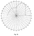
- Fig. 10 The embodiment of the averaged vector of angle of signal arrival estimate distribution is illustrated in Fig. 10, and operates in the following manner.
- the input elements of the averaged estimate distribution vector of angle of signal arrival analyzer 22 are written to RAM 36. Then these elements are read into the top element determiner 37, bottom element determiner 38, maximum element determiner 39, andcorrection values calculator 42.
- the maximum element of the averaged vector of angle of signal arrival estimate distribution that is chosen is transmitted to the top element determiner 37, to the bottom element determiner 38, and to the corrective values calculator 42.
- the top element determiner 37 of the averaged vector of angle of signal arrival estimate distribution the top element is determined as the top boundary of the group of elements of the averaged vector of angle of signal arrival estimate distribution that exceeds the given threshold. For this group of elements that are above the maximum element, single threshold non-exceedings are permitted, as well as one group threshold non-exceeding from two or three neighbor elements.
- the bottom element determiner 38 the bottom element of the averaged vector of angle of signal arrival estimate distribution is determined analogously.
- corrective values calculator 42 At the inputs of corrective values calculator 42, the values of the top, the bottom, arid the maximum elements of vector of angle of signal arrival estimate distribution are transmitted.
- the corrective values calculator 42 the sum of the elements of the averaged vector of angle of signal arrival estimate distribution that are below the bottom element is determined and the sum of the elements of the averaged vector of angle of signal arrival estimate distribution that are below the top element is also determined.
- the correction amendment for the bottom element that depends on the sum of the elements of the averaged vector of angle of signal arrival estimate distribution, which is located below the bottom element, is determined, as well as correction amendment for the top element that depends on the sum of the elements of the averaged vector of angle of signal arrival estimate distribution, which is located above the top element.
- the correction value for the bottom and the top elements is determined depending on the maximum element position.
- the correction for the top element and the correction value are transmitted to the top boundary estimator 40.
- the correction amendment for the bottom element and the correction value are transmitted to node of the estimation of the bottom boundary 41.
- the adjusted estimate of the bottom boundary of the signal angular area is determined as the difference of the bottom element and the sum of the correction amendment for the bottom element and the corrective value.
- the adjusted estimate of the top boundary of the signal angular area is determined as the sum of the top element of the correction amendment for the top element and the correction value.
- the estimates of the top and bottom boundaries of the signal angular area from the output of the averaged vector of angle of signal arrival estimate distribution analyzer 22 are transmitted to the inputs of the antenna array weight coefficients in the reverse channel generator 6.
- the embodiment of the antenna array weight coefficients in the reverse channel generator 6 is presented in Fig. 11.
- the antenna array weight coefficients in the reverse channel generator 6 will be described herein below.
- the adjusted estimates of the bottom and the top boundaries of the signal angular area are the output signals of the averaged vector of angle of signal arrival estimate distribution analyzer 22 and are transmitted to the input of of the weight vector of antenna array in the forward channel generator 6, namely at the inputs of correlation matrix generator 43 and estimate of average angle of signal arrival generator 44.
- Functional scheme of the weight vector of antenna array in the forward channel generator 6 may be realized on modern microprocessors of digital signal processing (DSP), such as a TMS 320Cxx, a Motorola 56xxx, an Intel, etc.
- DSP digital signal processing
- the calculated weight coefficients of the antenna array elements are transmitted to the first input of ratios of the antenna array elements amplitude coefficients generator 47 and to the output of the antenna array pattern weight coefficients in the forward channel generator 6.
- correlation matrix generator 43 using the estimates of the bottom and the top boundaries of the signal angular area ⁇ and 1 , ⁇ and 2 , the elements of the correlation matrix K are calculated in accordance with the Equation (14).
- the elements of the correlation matrix are transmitted to the input of Cholesky transformation node 45, where, using the algorithm proposed in, for example, J. Golub, Ch. Van Loun. Matrix calculations. M.: Mir, 1999, p. 134, and P. Horn, Ch. Jonson. Matrix analysis. M.: Mir, 1989, p. 141, the bottom triangular matrix is determined, the elements of which are transmitted to the first input of ratios of the antenna array pattern element amplitude coefficients generator 47. In this generator, the processing algorithm that is presented in Fig. 12 may be realized.
- Fig. 12 is a flowchart of the operation of ratios of amplitude coefficients of antenna array elements generator 47.
- the proposed algorithm of ratios of the antenna array pattern element amplitude coefficients generator 47 includes the following order of operations.
- ⁇ i.e. the ratio of the antenna array elements amplitude coefficients to amplitude coefficient of the antenna array element from which pilot signal is transmitted
- ⁇ i.e. the ratio of the antenna array elements amplitude coefficients to amplitude coefficient of the antenna array element from which pilot signal is transmitted
- ⁇ i.e. the ratio of the antenna array elements amplitude coefficients to amplitude coefficient of the antenna array element from which pilot signal is transmitted
- the ratio ⁇ ( ⁇ ) of average powers of statistically non-coherent and statistically coherent summands of info signal model that is received by the user is calculated in step 1203.
- This signal is transmitted at the input of normalization coefficients generator 48 and at the first input of the antenna array elements amplitude coefficients generator 49.
- the normalization coefficient k is determined based on the received value ⁇ and from the number of the antenna array elements.
- the value of the normalizing coefficient k transmits to the second input of the antenna array elements amplitude coefficients generator 49, where by the obtained value ⁇ and the normalization coefficient k amplitude weight coefficients are determined by Equation 20.
- Amplitude weight coefficients along with the phase coefficients are the output signals of the antenna array elements weight coefficients in the forward channel generator 6.
- the obtained amplitude and phase coefficients of the antenna array elements are used for the transmission of information signal to the user in the forward channel.
- Controller 14 may be realized on the modern microprocessors of digital signal processing (DSP), such as a TMS 320Cxx, a Motorola 56xxx, an Intel, etc.
- DSP digital signal processing
- Search block 13 in the proposed device may be implemented as it is shown in Zhuravlev V.I. "Search and Synchronization in Broadband Systems", M., Radio and communications, 1986, p.24.
- Figs. 14, 15, and 16 the antenna patterns of the forward channel for different signal angular areas (built in accordance with the presented method) are presented.
- the second embodiment of a BS adaptive antenna array pattern forming consists of the following:
- the search of user signal is carried out by determining the time positions of path signals, the signal with the maximum power is chosen. Then, the estimate of average angle of signal arrival is periodically formed, and the complex correlation pilot signal responses of the antenna array elements are determined.
- the complex correlation pilot signal responses at the antenna array output are determined by adding the products of the complex correlation pilot signal responses of antenna array elements to corresponding complex coefficients of each direction.
- the modules of complex correlation pilot signal responses at the antenna array output for L different directions are determined.
- the combined correlation response of the pilot signal at the antenna array output is determined by summing the modules of complex correlation pilot signal responses at the antenna array output for L different directions, and the maximum correlation response is determined.
- the normalized combined complex correlation pilot signal responses at the antenna array output L for different directions are determined by finding the ratios of complex correlation pilot signal responses at the antenna array output for L different directions to maximum combined correlation response.
- the complex weight coefficients of the antenna array elements in the reverse channel during the reception of the users' signal are determined by finding the ratios of complex correlation pilot signal responses at the antenna array output for L different directions to maximum combined correlation response.
- the antenna array pattern values are determined in the reversed channel.
- the maximum value (from the formed values of antenna array pattern in the reverse channel) is determined.
- the normalized values of the antenna array pattern in the reverse channel for L different directions are determined by finding the ratio of values of antenna array pattern to the maximum value.
- the decision function is determined by fulfilling the weighed combining of the normalized combined complex correlation pilot signal response at the antenna array output and normalized value of the antenna array pattern in the reversed channel.
- the direction of the decision function maximum is determined by generating the estimate of average angle of signal arrival.
- the phase coefficients of antenna array elements are determined using the formed estimate of average angle of signal arrival.
- the amplitude coefficients of the antenna array elements are set equal to each other, amplitude and phase coefficients of the antenna array elements are used to transmit the signal to the user.
- the number of additives is to be permanent or to be chosen adaptively depending on the estimate of signal fading.
- the antenna array pattern determination in the forward channel is carried out by the signal of the reverse channel.
- the maximum time path is chosen based on its power path signal.
- the maximum estimate of average angular path power signal arrival is set.
- the antenna pattern of adaptive antenna array in the forward channel is determined, the maximum of which is set in the direction of the estimate of average angular of signal arrival.
- Complex weight coefficients are determined by: where ⁇ and is the estimate of average angular of signal arrival in the reverse channel.
- the algorithm of determination of the direction MS signal arrival ⁇ is based on weigh coefficients vector of the reverse channel usage as well as the pilot signal accumulation and consists of the following.
- Non-coherent accumulation of M modules of complex correlation responses are determined by the following:
- the number of additives is set, to be permanent or is chosen adaptively depending on signal fading frequency, in such a way that the full duration of non-coherent accumulation is determined over several fading periods. Otherwise, due to fade-out of useful signal, the error in the estimate of angle of arrival is possible.
- Equation 24 The value obtained from Equation 24 is normalized yielding:
- Equation 26 The value obtained in Equation 26 is normalized yielding:
- the decision function is formed as the weighted sum of Equations (25) and (27) where a is a weight coefficient.
- Equation (28) The desired estimate ⁇ and of average angular of MS signal arrival is determined by the position of decision function maximum in Equation (28), as given by:
- the proposed device contains N correlators 2.1 - 2.
- N L decision function of the direction calculators 7.1 - 7.
- L the first inputs of which are the inputs of the correlation responses of pilot signal of the antenna array elements and are connected to the outputs of the corresponding correlators 2.1- 2.
- N a search block 13, a controller 14, antenna array weight coefficients in the reverse channel generator 5, a first normalization block 15, a second combiner 16, angle of signal arrival estimator 19, antenna array weight coefficients in the forward channel generator 6, and also scaling block 17 and second normalization block 18.
- N are the input signals and are connected to the device inputs.
- N are reference signals and are connected to the reference output of reference signal generator 1.
- the input of reference signal generator 1 is connected to the output of controller 14 that provides the synchronous functioning of the device.
- the first search block 13 is connected to the input of the device, the second input of search block 13 is connected to the output of controller 14, and the output of search block 13 outputs the search decision function and is connected to the input of controller 14.
- L contains N -1 multipliers 8.2 - 8. N , first combiner 9, module calculator 10, complex direction coefficients 11, discrete values of the antenna array pattern in the reverse channel calculator 12, and reset combiner 23.
- First inputs of multipliers 8.2 - 8. N and first input of first combiner 9 are connected to outputs of correlators 2.1 - 2.
- outputs of multipliers 8.2 - 8. N are connected to the inputs of combiner 9, starting from the second and up to N.
- the output of combiner 9 is the complex correlation response of direction pilot signal at the output of the antenna array and is connected to the input of module calculator 10.
- the output of module calculator 10 is the module of direction pilot signal complex correlation response at the output of the antenna array and is connected to the first input of reset combiner 23, the second input of the reset combiner 23 which is a reset signal from controller 14.
- the output of reset controller 23 is the pilot signal combined correlation response at the output of the antenna array and the first output of each direction decision function calculation block 7.1 - 7. L , and is connected to the corresponding input of the first normalization 15.
- the first input of discrete values of the antenna array pattern in the reverse channel calculator 12 is the second input of each block of calculation of decision function of direction 7.1 - 7. L and is connected to the output of weight vector of antenna array in the reverse channel generator 5 generating at its output weight coefficients of antenna array elements in the reverse channel. Signal inputs of weight vector of the antenna array in the reverse channel generator 5 are connected to the input of the device.
- the second input of discrete values of the antenna array pattern in the reverse channel generator 12 and second inputs of multipliers 8.2 - 8. N are connected to the output of complex direction coefficients 11 which outputs the complex coefficients for the given direction.
- the output of discrete values of the antenna array pattern in the reverse channel calculator 12, which is the second output of decision function of direction calculators 7.1 - 7. L , and outputs values of antenna array pattern in the reverse channel, is connected to the corresponding input of second normalization block 18.
- first normalization block 15 which outputs normalized modules of decision function of all L directions, is connected to the first input of second combiner 16.
- second normalization block 18 outputs the normalized values of the antenna array pattern in the reverse channel of all L directions and is connected to the input of scaling block 17.
- the output of scaling block 17 outputs the weighted normalized values of the antenna array pattern in the reverse channel for L directions and is connected to the second input of second combiner 16.
- the output of second combiner 16 is the values of decision function for L directions and is connected to the input of angle of signal arrival estimator 19, the output of which is the estimate of the average angle of signal arrival and is connected to the input of weight coefficients of antenna array in the forward channel generator 6.
- the output of weight coefficients of antenna array in the forward channel generator 6 is the output of amplitude and phase coefficients of antenna array elements.
- the complex multipath signal supplied from outputs N of antenna array elements is fed to first (signal) inputs of correlators 2.1-2. N and outputs of weight coefficients in the reverse channel generator 5.
- search block 13 At the same time the complex multipath signal supplied from the first antenna array element is fed to the input of search block 13.
- Search block 13 generates the decision function of path signal search in discrete time positions.
- This information of search block 13 is sent to controller 14, which compares the obtained values of the decision function with the threshold and determines time positions of path signals by determining which values exceed the threshold.
- controller 14 the obtained values of the decision function for detected path signals are compared between each other, and time position of the path signal with the maximum value of the decision function is determined.
- the reference signal corresponding to the path signal with the maximum power is fed from the output of reference signal generator 1, and to second inputs of correlators 2.1-2. N .
- the correlation responses of the pilot signal of antenna array elements are fed to first inputs of L decision function of direction calculators 7.1-7. L , namely to the first input of combiner 9, and to first inputs of corresponding (complex) multipliers 8.2-8. N .
- the number of L blocks of calculation of decision function 7.1-7. L is equal to the number of considered directions of the researched angular area.
- the complex weight coefficients of adaptive antenna array elements in the reverse channel are generated during reception of the subscriber signal according to one of algorithms proposed, for example, in R. A. Monzingo, T.U. Miler. Adaptive antenna arrays. /M.: Radio and communication, 1986, p. 77-90. These coefficients are fed to second inputs of decision function of direction calculators 7.1-7. L , and namely to first inputs of discrete values of antenna array pattern in the reverse channel calculators 12.
- Output signals of multipliers 8.2-8. N and complex correlation responses of the pilot signal of the first antenna array element supplied from the output of first correlator 2.1 are fed to inputs of combiner 9 where they are combined.
- a signal supplied from the output of combiner 9 corresponds to the complex correlation response of the pilot signal at the output of the antenna array for ⁇ i direction.
- This signal is fed to the input of module calculator 10 where the square root of the sum of squares of the real and imaginary part of the signal is calculated.
- the output signal of module calculator 10 is equal to the module of complex correlation response of the pilot signal at the output of antenna array for ⁇ i direction.
- This signal is supplied from the output of module calculator 10 to the first input of reset combiner 23, to the second input of which the control reset signal is supplied from controller 14.
- the number of M noncoherent components is set either constant or selected adaptively depending in the signal fading frequency so that the full duration of the non-coherent accumulation is determined for several fading periods.
- L is the combined correlation response of the pilot signal at the output of the antenna array Z ( ⁇ i ) of ⁇ i direction, and is fed to the corresponding to input of normalization block 15.
- the maximum combined correlation response of the pilot signal is determined at the output of antenna array by comparing the combined correlation responses of the pilot signal at the output of antenna array Z ( ⁇ i ) of different directions, and the normalized combined correlation responses of the pilot signal at the output of the antenna array are generated for L different directions.
- the normalization is performed by determining ratios of combined correlation responses of the pilot signal at the output of antenna array for L different directions, and the maximum combined correlation response.
- the obtained normalized signals for L different directions are fed to first inputs of combiner 16.
- the values of the antenna array pattern in the reverse channel are generated according, " Smart Antennas for Wireless Communications", as indicated above, and which are transmitted to inputs of normalization block 18.
- the maximum value of the antenna array pattern in the reverse channel is determined by comparing values of the antenna array pattern in the reverse channel of different directions with each other, and normalized values of the antenna array pattern in the reverse channel are generated for L different directions.
- the normalization is performed by determining the ratio of values of the antenna array pattern in the reverse channel for L different directions to the maximum value.
- the obtained normalized values of the antenna array pattern in the reverse channel for L different directions are fed to the input of scaling block 17.
- Scaling block 17 generates the weighted values of the normalized antenna array pattern in the reverse channel for L different directions by multiplying values of the normalized antenna array pattern by a weight coefficient that is fed to the second input of combiner 16.
- the searched estimate ⁇ and of the average angle of signal arrival in the reverse channel is determined by the position of direction of the decision function maximum.
- Estimate ⁇ and of the average angle of signal arrival in the reverse channel is fed to the input of weight vector of the antenna array in the foward channel generator 6, in which, for example, according to the algorithm discussed above, phase coefficients of antenna array elements are determined using the generated estimate of the average angle of arrival of the signal taking into account the geometry of the antenna array. Amplitude coefficients of antenna array elements are set equal to each other.
- the obtained complex weight coefficients of antenna array elements are utilized to transmit the signal to the subscriber in the forward channel.
Abstract
Description
- This application claims priority to an application entitled "PATTERN FORMING METHOD AND DEVICE FOR AN ADAPTIVE ANTENNA ARRAY OF A BASE STATION", filed in the Russian Federal Institute of Industrial Property and assigned Serial No. 2002103215, the contents of which are incorporated herein by reference.
- The invention relates generally to radio engineering, and particularly, to methods of radio signal reception and transmission using adaptive antenna arrays in CDMA (Code Division Multiple Access) cellular communications systems. Also, the present invention can be applied to BTS (Base Transceiver Station) receiving devices that form an antenna pattern for each mobile user in both the reverse and forward channels.
- The use of an adaptive antenna array in CDMA BTS considerably improves communication quality and system capacity, and expands a BTS coverage area. Consequently, all third generation (3G) standards require use of the adaptive antenna array in a BTS.
- The following conventional approaches to form an antenna pattern of a smart antenna in the forward channel are known in the art.
- According to a first approach, a weight vector of antenna array elements obtained while receiving a signal in a reverse channel is used for signal transmission in a forward channel. This approach is described in Joseph C. Liberti, Theodore S. Rappaport, "Smart Antennas for Wireless Communication", Prentice Hall PTR, 1999, and in United States patents: 6,031,877 to Simon Saunders, entitled "Apparatus and Method for Adaptive Beam forming in an Antenna Array" granted Feb. 29, 2000; and 6,122,260 to Hui Liu, Guanghan Xu entitled "Smart Antenna CDMA Wireless Communication System" granted Sep. 19,2000. The contents of all of the above referenced documents are incorporated herein by reference. This approach is most efficient in TDD (Time Division Duplexing) communication systems.
- In TDD systems, the forward and reverse channels are time divided and matched in the carrier frequency. Therefore the direction of the signal traveling from the mobile station (MS) to base station (BS), which is determined by an MS signal, matches a direction of the signal traveling from the BS to the MS. However, for FDD (Frequency Division Duplexing) CDMA systems, the applicability of this method is hardly possible because changes in the carrier frequency might result in considerably different multipath characteristics in the forward and reverse channels.
- According to a second approach based on a training signal, an MS estimates forward channel parameters and the estimate is supplied to a BTS via a reverse channel. Based on this estimate, the BTS corrects SA (Smart Antenna) weight factors in the forward channel. This approach is described in article Ayman F. Naguib, Arogyaswami Paulrai, Thomas Kalath. "Capacity Improvement with Base-Station Antenna Arrays in Cellular CDMA", IEEE Trans. Veh. Technol, vol. 43, no. 3, pp. 691 - 698, August 1994, and in United States patent 5,828,658 to Bjorn E. Ottersten, Craig H. Barratt, David M. Parish, Richard H. Roy entitled "Spectrally Efficient High Capacity Wireless Communication Systems with Spatio-Temporal Processing" granted Oct. 27, 1998. The contents of all of the above referenced documents are incorporated herein by reference.
- The disadvantages of this approach are that a substantial amount of data must be transmitted via the reverse channel to provide feedback and that a long response time of feedback is required. In addition, the use of feedback is impossible in some cellular communications systems, particularly, the 3GPP2 system.
- According to a third approach, a direction of arrival of a strongest component of a mobile user multipath signal is determined (see Joseph C. Liberti, Theodore S. Rappaport, "Smart Antennas for Wireless Communication, Prentice Hall PTR", 1999, and United States patent 6,108,565 to Shimon B. Scherzer entitled "Practical Space-Time Radio Method for CDMA Communication Capacity Enhancement" granted Aug. 22, 2000). This direction is considered as the main direction of a signal traveling from a BTS to an MS. Complex coefficients of the antenna array elements in the forward channel are selected so that the main lobe of the forward channel antenna pattern is oriented in this direction. The width of the main lobe can be determined by an angle sector of the signal.
- One possible operation of the third approach is a consequential method disclosed in United States patent 6,108,565. In the method of space-time signal processing a switch beam forming method is used. The width of an antenna beam lobe depends on the distance from mobile users to BTS. If mobile users are in a close vicinity of the BTS, the lobe corresponding to them becomes wider. When mobile users are far away from the BTS, the lobe corresponding to them becomes narrower. Due to the fact that this approach requires information on a distance to the mobile users due to the consequential character of angle spread estimation, it cannot have sufficient accuracy.
- A pattern forming method for an adaptive antenna array is described in United States patent 6,108,565, and is the closest to the proposed solution in the prior art (hereinafter referred to as the "prototype").
- The method of utilizing the prototype is described as follows. For each path, weight coefficients of antenna array elements are generated in order to periodically perform the following operations: first, the input signal is demodulated at antenna array elements, then fast Hadamard transformation of the demodulated input signal at the antenna array elements is performed generating the input signal matrix, the input signal matrix is multiplied by the matrix of reference signals, the estimate of the angle of arrival of the input path signal is determined by analyzing the multiplication result of the input signal matrix and matrix of reference signals, the current value of the weight vector is determined as the vector that corresponds to the estimate of the angle of arrival of the input path signal, current values of weight vectors of paths are output and used to determine a pattern of the adaptive antenna array, and the matrix of reference signals is determined by the signals that correspond to pre-determined discrete hypothesizes on the angle of arrival of the input signal.
- The estimate of an angle of an arrival of an input signal determines a weight vector according to Equation 1 below:where = 2π / λd sin , λ is a wavelength, d is a distance between antenna array elements, and N is a number of antenna array elements.

- In order to implement this method the prototype (conventional) device comprising L path signal processing blocks, which is illustrated in Fig.1, is used. As illustrated in Fig. 1, the device comprises L path signal processing blocks. Each of L path signal processing blocks contains N parallel channels, consisting of successively connected correlators 2 and fast Hadamrd transformers 3. Also, the device consists of a reference signal generator 1,matrix multiplier and analyzer 4, weight vector of reverse channel antenna array generator 5, and weight vector of forward channel antenna array generator 6.
- First inputs of correlators 2.1 - 2.N are signal inputs and also inputs of the device. The second inputs are reference inputs and combine with the output of reference signal generator 1. The output of each fast Hadamar transformer 3.1 - 3.N is connected to the corresponding inputs of matrix multiplier and analyzer 4, the output of which is supplied as the input of weight vector of reverse channel antenna array generator 5. A first output of weight vector of reverse channel antenna array generator 5 is the output of the current weight vector of the reverse channel and the first output of the path signal processing block of the device. A second output of weight vector of reverse channel antenna array generators is supplied as the input of weight vector of forward channel antenna array generator 6. The output of weight vector of forward channel antenna array generator 6 is the output of the current weight vector in the forward channel and second output of the path signal processing block of the device.
- The prototype (conventional) device illustrated in Fig. 1 operates in the following manner.
- According to the description above of the prototype, in each of L path signal processing blocks, a complex input signal is fed to first (signal) inputs of correlators 2.1 - 2.N. A reference PN sequence is supplied from reference signal generator 1 to second (reference) inputs of correlators 2.1 - 2.N. The state of reference signal generator 1 corresponds to the value of the time position of the path signal in the multipath signal to be received. Complex demodulated signals supplied from outputs of correlators 2.1 - 2.N are fed to inputs of the corresponding fast Hadamard transformers 3.1 - 3.N, where Hadamard basis decomposition of the input signal is performed. Spectrums of inputs signals supplied from outputs of fast Hadamard transformers 3.1 - 3.N are supplied to N inputs of matrix multiplier and analyzer 4. In block 4, the matrix of reference signals multiplies the input signal matrix. The inputs signal matrix is generated by the spectrums of input signals. The matrix of reference signals is determined by signals that correspond to pre-determined discrete hypothesizes on the angle of arrival of the input path signal.
- In addition, in the matrix multiplier and analyzer 4 the multiplication result of the input signal matrix and matrix of reference signals is analyzed and the estimate of the angle of arrival of the input path signal is determined. The estimate of the angle of arrival of the input path signal supplied from the output of the matrix multiplier and analyzer 4 is applied to the input of weight vector of reverse channel antenna array generator 5. Weight vector of reverse channel antenna array generator 5 generates the current weight vector of the reverse channel path at its first output based on the estimate of the angle of arrival of the input path signal. This weight vector is the first output signal of the device.
- The estimate of the angle of arrival of the input path signal supplied from the output of weight vector of reverse channel antenna array generators is fed to the input of weight vector of forward channel antenna array generator 6. Weight vector of forward channel antenna array generator 6 generates the current weight vector of the forward channel path at its output based on the estimate of the angle of arrival of the input path signal. This weight vector is the second output signal of the device.
- The width of the antenna beam lobe in the forward channel depends on the distance from mobile users to the BTS. If mobile users are in the close vicinity of the BTS, the lobe corresponding to them becomes wider. When mobile users are far away from the BTS, the lobe corresponding to them becomes narrower.
- This approach requires determining the distance to mobile users due to the consequential character of angle spread estimation and therefore does not have sufficient accuracy.
- Further drawbacks of this method are that in the presence of strong interferences from other users (high rate users, i.e., users with high data transmission rate) the desired signal can be cancelled by the interference and the correct solution about the direction of arrival and angular area of the desired signal cannot be determined.
- Therefore, the present invention has been designed in view of the above problems, and it is an object of the present invention to improve the interference canceling efficiency in the complex interference-signal environment in the presence of powerful interferences with arbitrary values of the desired signal, and interference angle sector including great ones.
- Two embodiments of the pattern forming method and device for a BTS adaptive antenna array are described herein below. The first embodiment of the antenna pattern forming method is applied to random values of user signals' angle spread, and in the second embodiment a method is applied to relatively small (e.g., less than 30 degrees) values of user signals' angle spread.
- The first embodiment of the pattern forming method for a BTS adaptive antenna array in which the common pilot signal is transmitted from one of the antenna array elements and an information signal is transmitted to each subscriber from all antenna array elements, and during reception of the subscriber signal the complex correlation responses of the pilot signal of antenna array elements are generated, the complex weight coefficients of antenna array elements in the reverse channel are generated, for each of L different directions of the researched angular area the decision function is generated, the direction of the decision function maximum is determined, the estimate of the average angle of arrival of the signal is generated, taking into account the geometry of the antenna array the phase coefficients of antenna array elements are determined using the generated estimate of the average angle of arrival of the signal. Before the generation of complex correlation responses of the pilot signal of antenna array elements for each subscriber, the search for the subscriber signal is performed to determine time positions of path signals, a path the signal of which has the maximum power is selected, the sequence of estimates of angle of signal arrival is generated, estimate of the angle of arrival of the signal after generation of complex correlation responses of the pilot signal of antenna array elements is generated, for each of L different directions of the researched angular area the complex correlation responses of the pilot signal are generated at the output of the antenna array combined products of complex correlation responses of the pilot signal of antenna array elements and corresponding complex coefficients of each direction, modules of complex correlation responses of the pilot signal are generated at the output of the antenna array for L different directions and the maximum module is determined, and normalized modules of complex correlation responses of the pilot signal are generated at the output of the antenna array for L different directions determining ratios of modules of complex correlation responses of the pilot signal at the output of the antenna array for L different directions and the maximum module.
- After generation of complex weight coefficients of the antenna array in the reverse channel for each of L different directions of the considered angular area the values of the antenna pattern in the reverse channel are generated, the maximum generated value of the antenna pattern in the reverse channel is determined, normalized values of the antenna pattern in the reverse channel are generated for L different directions determining ratios of values of the antenna pattern and the maximum value, and the decision function for each of L different directions of the researched angular area is generated performing the weighed combining of the normalized module of the complex correlation response of the pilot signal at the output of the antenna array and the normalized value of the antenna pattern in the reverse channel.
- While determining the direction of the decision function maximum the estimate of the angle of signal arrival is obtained as a direction of the decision function maximum,
the sequence of generated estimates of the angle of arrival of the signal is grouped in blocks, each having M estimates of the angle of signal arrival, and the sequence of estimate distribution vectors of angle of signal arrival of blocks is generated. In this case for each block the estimate distribution vector of angle of signal arrival of block of L length is generated by M generated estimates of angle of signal arrival of the block; each element of this vector corresponds to one of L directions of the researched angle area and is equal to the number of estimates of angle of signal arrival of the given direction, and the sequence of averaged estimate distribution vectors of angle of signal arrival is generated based on the sequence of estimate distribution vectors of angle of arrival of the signal of blocks using the sliding window. - For each averaged estimate distribution vector of angle of signal arrival estimates of the top and bottom boundaries of the angle signal area are determined, and estimate of the average angle of arrival is generated by obtained estimates of the top and bottom boundaries of the angle signal area.
- After determination of phase coefficients of antenna array elements, the correlation matrix of signals of antenna array elements is generated based on the obtained estimates of the top and bottom boundaries of the angle signal area, Cholesky transformation of the generated correlation matrix is performed obtaining the bottom triangular matrix, ratio of amplitude coefficients of antenna array elements and the amplitude coefficient of the antenna array element is determined, the pilot signal is transmitted from this antenna array element using the obtained bottom triangular matrix and phase coefficients of antenna array elements, the normalized coefficient is determined by the obtained ratio taking into account the number of antenna array elements, amplitude coefficients of antenna array elements are determined by multiplying the normalized coefficient by the ratio of amplitude coefficients of antenna array elements and the amplitude coefficient of the antenna array element from which the pilot signal is transmitted, and generated amplitude and phase coefficients of antenna array elements are used to transmit the information signal to the subscriber.
- The estimate of the bottom and top boundaries of the angle signal area is performed, for example, in the following manner: the maximum element of the averaged estimate distribution vector of angle of arrival of the signal is determined, the bottom and top elements are determined as boundaries of the group of elements of the averaged estimate distribution vector of angle of signal arrival; in this case this group of elements comprises the maximum element of the averaged estimate distribution vector of angle of signal arrival and elements of the group exceed the threshold, however, in either of the directions of the maximum element a single non-exceeding of the threshold as well as a group one, two of three elements placed near one another, are allowed, the sum of elements of the averaged estimate distribution vector of angle of signal arrival that are located below the bottom element is determined and the sum of elements of the averaged estimate distribution vector of angle of signal arrival that are located above the top element is also determined, the correcting amendment is generated for the bottom element, this amendment depends on the sum of elements of the averaged estimate distribution vector of angle of signal arrival that are located below the bottom element and the correcting amendment is generated for the top element, this amendment depends on the sum of elements of the averaged estimate distribution vector of angle of signal arrival that are located above the top element, the correction value is determined both for the bottom and top elements, the value being dependent on the position of the maximum element of the averaged estimate distribution vector of angle of signal arrival, the estimate of the bottom boundary of the angle signal area is determined as a difference of the angle coordinate corresponding to the bottom element, and the sum of the correcting amendment is determined for the bottom element and the correction value, and the estimate of the top boundary of the angle signal area is determined as a sum of the angle coordinate corresponding to the top element, correcting amendment for the top element and correction value.
- The estimate of the average angle of signal arrival can be generated as a half-sum of estimates of the bottom and top boundaries of the angle signal area.
- The ratios of amplitude coefficients of antenna array elements and the amplitude coefficient of the antenna array element from which the pilot signal is transmitted can be equal to each other. This ratio is determined as the maximum value within the interval from 0 to 1 for which the ratio of average powers of the statistically coherent and statistically non-coherent components of the model of the information signal received by the subscriber does not exceed the given value.
- The second embodiment of the forward channel pattern forming method for BTS adaptive antenna array consists of receiving the subscriber signal while the complex correlation responses of the pilot signal of antenna array elements are generated, the complex weight coefficients of adaptive antenna array elements in the reverse channel are generated, for each of L different directions of the researched angular area the decision function is generated, the direction of the decision function maximum is determined generating the estimate of the average angle of signal arrival, and taking into account the geometry of the antenna array the phase coefficients of antenna array elements are determined using the generated estimate of the average angle of arrival of the signal.
- Before generation of complex correlation responses of the pilot signal of antenna array elements for each subscriber, the search for the subscriber signal is performed determining time positions of path signals, a path the signal of which has the maximum power is selected, and the estimate of the average angle of arrival of the subscriber signal is generated periodically. After generation of complex correlation responses of the pilot signal of antenna array elements in the reverse channel, for each of L different directions of the researched angular area the complex correlation responses of the pilot signal are generated at the output of the antenna array combining products of complex correlation responses of the pilot signal of antenna array elements and corresponding complex coefficients of each direction, modules of the complex correlation responses of the pilot signal are generated at the output of the antenna array for L different directions, the summed correlation response of the pilot signal is generated at the output of the antenna array combining the modules of complex correlation responses of the pilot signal at the output of the antenna array for L different directions and the maximum of the modules is determined, and the normalized summed correlation responses of the pilot signal are generated at the output of the antenna array for L different directions determining the ratios of the summed correlation responses of the pilot signal at the output of the antenna array for L different directions to the maximum summed correlation response.
- After generation of complex weight coefficients of antenna array elements in the reverse channel, for each of L different directions of the researched angular area the values of the antenna pattern are generated in the reverse channel, the maximum generated value of the antenna pattern is determined in the reverse channel, normalized values of the antenna pattern are generated in the reverse channel for L different directions determining the ratio of values of the antenna array and the maximum value, and the decision function for each of L different directions of the researched angular area is generated performing the weighed combining of the normalized summed correlation response of the pilot signal at the output of the antenna array and normalized value of the antenna array in the reverse channel. After generation of the average angle of signal arrival and phase coefficients of antenna array elements, amplitude coefficients of antenna array elements are set equal to each other, amplitude and phase coefficients of antenna array elements are used to transmit a signal to the subscriber.
- While combining the modules of complex correlation responses of the pilot signal at the output of the antenna array for L different directions the number of components is either set constant or selected adaptively depending on the estimate of the signal fading frequency.
In order to solve the problem the first embodiment of the forward channel pattern forming device for BTS adaptive antenna array comprising N correlators, the reference signal generator, the angle of signal arrival estimator, the weight vector of antenna array in the reverse channel generator, and the weight vector of antenna array in the forward channel generator, where first inputs of correlators are signal inputs and connected to the inputs of the device, second inputs of correlators are reference inputs and joint with the output of the reference signal generator. - L blocks of calculation of decision function for different directions, each containing N - 1 multipliers, the first combiner, module calculator, block of complex direction coefficients , and discrete values of antenna pattern in the reverse channel calculator. The following blocks are also added: the search block, controller, first and second normalization blocks, second combiner, scaling block, estimate distribution vector of angle of signal arrival generator, averaged estimate distribution vector of angle of signal arrival generator, averaged estimate distribution vector of angle of signal arrival analyzer, where the first input of the search block is connected to the first input of the device, the second input of the search block is the control and connected to the output of the device, the output of the search block is the output of the search decision function and connected to the input of the controller, the input of the reference signal generator is the control and connected to the output of the controller, providing the synchronous operation of blocks of the device, first inputs of N - 1 multipliers and the first input of first combiner is first inputs of the decision function of direction calculator and are connected to the outputs of the corresponding correlators.
- Generating the correlation responses of the pilot signal of antenna array elements at these outputs, the outputs of the multipliers are connected to the inputs of first combiner, from the second one to N-th, the output of first combiner is the output of the complex correlation response of the pilot signal of the given direction at the output of the antenna array and is connected to the input of the module calculation block, and the first output of each decision function of direction calculator and is connected to the corresponding input of first normalization block, the first input of the discrete values of antenna array in the reverse channel calculator is the second input of each decision function of direction calculator and is connected to the output of the weight vector of antenna array in the reverse channel generator generating the weight coefficients of antenna array elements in the reverse channel, signal inputs of the weight vector of antenna array in the reverse channel generator is connected to the inputs of the device, the second input of the block of calculation of discrete values of antenna pattern in the reverse channel and second inputs of N - 1 multipliers are combined and connected to the outputs of the complex direction coefficients which outputs complex coefficients of the given direction, the output of the block of calculation of discrete values of antenna pattern in the reverse channel which is the second output of the block of calculation of decision function of direction and the output of the value of the antenna array pattern in the reverse channel of the given direction is connected to the corresponding input of second normalization block.
- The output of first normalization block which is the output of the normalized modules of complex correlation responses of the pilot signal at the output of the antenna array of all L directions is connected to the first input of second combiner, the output of second normalization block is the output of normalized values of antenna array pattern in the reverse channel of all L directions and is joint with the input of the scaling block, the output of the scaling block is the output of weighed normalized values of antenna array pattern in the reverse channel for L directions and is joint with the second input of second combiner, the output of second combiner is the output of values of the decision function for L directions and is connected to the input of the angle of signal arrival estimator, the output of which is the output of the estimate of the average angle of signal arrival is connected to the input of the estimate distribution vector of angle of signal arrival generator, at the output generating the sequence of estimate distribution vectors of angle of signal arrival, the output of the estimate distribution vector of angle of signal arrival generator is connected to the first input of averaged estimate distribution vector of angle of signal arrival generator, the second input of which is the control and is connected to the output of the controller, the output of the averaged estimate distribution vector of angle of signal arrival generator is the output of the sequence of averaged estimate distribution vectors of angle of signal arrival and is connected to the input of the estimate distribution vector of angle of signal arrival analyzer generate the estimates of the top and bottom boundaries of the angle signal area, the outputs of the estimate distribution vector of angle of signal arrival analyzer are connected to the corresponding inputs of the weight vector of antenna array pattern in the forward channel generator, the outputs of the weight vector of antenna array pattern in the forward channel generator are the outputs of amplitude and phase coefficients of antenna array elements.
- In order to solve the given problems the second embodiment of the forward channel pattern forming device for BTS adaptive antenna array comprising N correlators, the reference signal generator, angle of signal arrival estimator, weight vector of antenna array in the reverse channel generator, and weight vector of antenna array in the forward channel generator, where first inputs of correlators are signal inputs and connected to the inputs of the device, second inputs of correlators are reference inputs and connected to the output of the reference signal generator.
- L blocks of calculation of decision function for different directions, each containing N - 1 multipliers, first combiner, module calculation block, reset combiner, complex direction coefficients and discrete values of antenna array pattern in the reverse channel calculator. Also included are the search block, controller, first and second normalization blocks, second combiner, scaling block, where the first input of the search block is connected to the first input of the device, the second input of the search block is the control and is connected to the output of the controller, the output of the search block is the output of the decision function of search and is connected to with the input of the controller, the input of the reference signal generator is the control and is connected to the output of the controller, providing the synchronous operation of blocks of the device.
- First inputs of N - 1 multipliers and the first input of first combiner are first inputs of the block of calculation decision function of direction and are connected to the outputs of the corresponding correlators generating the correlation responses of the pilot signal of antenna array elements at their outputs, the outputs of multipliers are connected to the inputs of first combiner beginning from the second one to N-th, the output of first combiner is the output of the complex correlation response of the pilot signal of the given direction at the output of the antenna array and is connected to the input of the module calculation block, the output of which is the output of the module of the complex correlation response of the pilot signal of the given direction at the output of the antenna array and is connected to the first input of the reset combiner, the second input of which is the input of the reset signal and is connected to the output of the controller, the output of the reset combiner is the output of the combined correlation response of the pilot signal of the given direction at the output of the antenna array and the first output of each of the decision function of direction calculators and is connected to the corresponding input of first normalization block, the first input of the discrete values of antenna array pattern in the reverse channel calculator is the second input of each decision function of direction calculator and is connected to the output of the weight vector of antenna array in the reverse channel generator generating the weight coefficients of antenna array elements in the reverse channel at the output of the antenna array, the signal inputs of the weight vector of antenna array in the reverse channel generator are connected to the inputs of the device, the second input of the discrete values of antenna array pattern in the reverse channel calculator and second inputs of N - 1 multipliers are combined and connected to the output of the complex direction coefficients which is the output of complex coefficients of the given direction, the output of the discrete values of antenna array pattern in the reverse channel calculator which is the second output of the decision function of direction and the output of the value of the antenna array pattern in the reverse channel calculator of the given direction is connected to the corresponding input of second normalization block.
- The output of first normalization block which is the output of normalized combined modules of complex correlation responses of the pilot signal at the output of the antenna array of all L directions is connected to the first input of second combiner, the output of second normalization block is the output of normalized values of the antenna array pattern in the reverse channel of all L directions and is connected to the input of the scaling block, the output of the scaling block is the output of weighed normalized values of the antenna array pattern in the reverse channel for L directions and is joint with the second input of second combiner, the output of second combiner is the output of values of decision function for L directions and is connected to the input of the angle of signal arrival estimator the output of which is the output of the estimate of average angle of signal arrival and is joint with the input of the weight vector of antenna array pattern in the forward channel generator, the outputs of the weight vector of antenna array pattern in the forward channel generator are the outputs of amplitude and phase coefficients of antenna array elements.
- The comparative analysis of the first and second embodiments of the method and device of generation of base station adaptive antenna array pattern with the prototype shows that the proposed inventions differ significantly from the prototype since they improve interference canceling in complex interference-signal environment.
- The above and other features, objects, and advantages of the present invention will become more apparent from the detailed description set forth below when taken in conjunction with the drawings wherein like reference characters correspond throughout, in which:
- Fig. 1 is a block diagram of a conventional device;
- Fig. 2 illustrates an antenna array pattern forming in a forward channel;
- Fig. 3 illustrates an example of sliding window usage for obtaining an averaged vector of an estimated distribution of an angle of a signal arrival;
- Fig. 4 illustrates an example of top and bottom element determination;
- Fig 5 illustrates an example of a highly elevated bottom element under an influence of powerful interference;
- Fig. 6 illustrates an example of an antenna array elements numbering order;
- Fig. 7 is a block-diagram of a first embodiment of the present invention;
- Fig. 8 illustrates an embodiment of the vector of estimate distribution of angle of signal arrival generator;
- Fig. 9 illustrates an embodiment of the averaged vector of estimate distribution of angle of signal arrival generator;
- Fig. 10 illustrates an embodiment of the vector of estimate distribution of angle of signal arrival analyzer;
- Fig. 11 illustrates an embodiment of the forward channel antenna array weight coefficients vector generator;
- Fig. 12 illustrates an operation algorithm of a ratio generation node of antenna array elements amplitude coefficients;
- Fig. 13 is a block diagram of a second embodiment of the present invention;
- Fig.14 illustrates an antenna pattern of a forward channel, where

- Fig.15 illustrates an antenna pattern of a forward channel, where
and

- Fig.16 illustrates an antenna pattern of a forward channel, where

-
- Preferred embodiments of the present invention will be described in detail herein below with reference to the annexed drawings. In the following description, a detailed description of known functions and configurations incorporated herein will be omitted when it is not necessary to describe the subject matter of the present invention.
- In the first embodiment of the present invention, a first method of antenna pattern forming of a BS adaptive antenna array, during which the common pilot signal is transmitted from one of the antenna array elements and an information signal is transmitted to each user from all the antenna array elements, will be described herein below.
- For each user, the search for user signal is carried out by determining the time positions of path signals, the signal with the maximum power is selected. Next, the estimated sequence of the angle of the signal arrival is determined.
For generation of each angle of signal arrival estimate, the complex correlation pilot signal responses of the antenna array elements are formed. For each of L different directions i,i =1,L of the researched angular area the complex correlation pilot signal responses at the antenna array output are formed by adding the products of the complex correlation pilot signal responses of antenna array elements to corresponding complex coefficients of each direction. The modules of complex correlation pilot signal responses at the antenna array output for L different directions are formed and the maximum one is to be determined Normalized modules of complex correlation pilot signal responses at the antenna array output for L different directions are formed by determining the ratios of complex correlation pilot signal responses at the antenna array output for L different directions modules to the maximum module. The complex weight coefficients of the adaptive antenna array elements in the reverse channel are determined during user signal reception. - For each of L different directions i,i =
1,L of the researched angular area, the value of the antenna array pattern in the reverse channel is determined. The maximum of the determined values of the antenna array pattern in the reverse channel is determined. Then normalized values of the antenna array pattern in the reverse channel for L different directions is determined by finding the ratios of the antenna array pattern in the reverse channel values to the maximum value. - For each of L different directions i,i =
1,L of the researched angular area, the decision function is determined fulfilling the weighed combining of the normalized module of complex correlation pilot signal response at the antenna array output and the normalized value of the antenna array pattern in the reverse channel. The angle of arrival estimate is determined as a decision function maximum direction, and the sequence of the formed angle of arrival estimates is grouped into blocks each containing M estimates of angle of arrival. The sequence of vectors of block angle of signal arrival estimate distribution is determined for each block by M determined estimates of block signal angle of arrival, the vector of block angle of signal arrival estimates distribution the length of which is L, each element of which corresponds to one of L directions of the researched angular area and is equal to the number of angle of arrival estimates of this direction. The sequence of the averaged vectors of angle of arrival estimates distribution is determined from the sequence of block angle of arrival estimates distribution using sliding window. - For each averaged vector of angle of arrival estimate distribution, the estimates of top and bottom boundaries of the angular area are to be determined, The estimate of the average angle of arrival is determined by the obtained estimates of the top and the bottom boundaries of the angular area. Considering the geometry of the antenna array, the phase coefficients of the antenna array elements are determined using the determined estimate of average angle of arrival. The correlation matrix of the antenna array element signals is determined by the estimates of the top and the bottom boundaries of signal angular area thus obtained.
- Further, Cholesky transformation of the formed correlation matrix is carried out, thus obtaining the bottom triangular matrix. The ratio of the antenna array elements amplitude coefficients to the amplitude coefficient of the antenna array element from which the pilot signal is transmitted is determined using the obtained bottom triangular matrix and phase coefficients of the antenna array. The normalized coefficient is determined by taking into account the number of the antenna array elements.
- The amplitude coefficients of the antenna array are determined by the multiplication of the standard coefficient by the ratio of the antenna array element amplitude coefficients to the amplitude coefficient of the antenna array element from which the pilot signal is transmitted.
- The generated amplitude and phase coefficients of the antenna array elements are used for transmission of the information symbol to a user.
- The estimation of the top and bottom boundaries of signal angular area are performed, for example, in the following manner.
- First, the maximum element of the averaged vector of angle of arrival estimates distribution is determined. Then, the top and bottom elements are determined as boundaries of the group of averaged angle of arrival estimate distribution vector, this group of the elements includes the maximum element of the averaged angle of arrival estimate distribution vector, and the elements of the group exceeds the threshold, but at each side from the maximum element single non-exceedings of the threshold can be permitted as well as one group non-exceeding of the threshold from two or three neighbor elements. The sum of the elements of the averaged angle of arrival estimates distribution vector is to be determined as well as the sum of the elements of the averaged angle of arrival estimates distribution vector that are located above the top element. The correction amendment for the bottom element is formed that depends on the sum of the elements of averaged angle of arrival estimates distribution that are located below the bottom element and the correction amendment for the top element is formed that depends on the sum of the elements of averaged angle of arrival estimates distribution that are located above the top element. The correction value for the top and the bottom elements is determined that depends on the location of the maximum element of averaged angle of arrival estimates distribution vector.
- The estimate of the bottom signal angular area boundary is determined as the difference of the angular coordinate that corresponds to the bottom element and is determined as the sum of the correction amendment for the bottom element and the correction value. The estimate of the top signal angular area boundary is determined as the sum of the angular coordinate that corresponds to the top element, the correction amendment for the top element and the correction value.
- The estimate of the average angle of arrival may be determined as a half-sum of the estimates of the top and the bottom boundaries of the signal angular area.
- The ratio of the antenna array amplitude coefficients to the antenna array amplitude coefficient from which the pilot signal is transmitted may be equal to each other, and this ratio is determined as the maximum value from the interval from 0 to 1. For this antenna array ratio, the ratio of the average powers statistically non-coherent and statistically coherent summands of information signal model that is received by the user does not exceed the given value.
- The proposed algorithm of the forward channel antenna pattern determined by the first embodiment consists of two stages. The first stage, the estimate of useful signal angular boundaries is determined. This estimate is carried out by the signal of the mobile user that is received by the BS. The second stage, the forward channel antenna pattern determination is fulfilled by the estimates of useful signal angular area boundaries that are obtained in the first stage.
- The first stage of the forward channel antenna pattern forming algorithm (the estimate of the angular boundaries of useful signal area), which includes using the reverse channel antenna array weight coefficients W up , consists of the following.
- For each of L different directions i,i =
1,L of the researched angular area, the module of "short" complex correlation pilot signal response at the antenna array output is determined bywhere a n ( i ) = exp [jπ(n-1)cos i ],n=
1,N , i=1,L represents complex coefficients of each direction, u n , n=1,N represents complex correlation pilot signal responses at the outputs of the antenna array elements correlators, N is a number of the antenna array elements. - The value of complex correlation pilot signal response module at the output of the antenna array from Equation 2 is normalized

- The discrete values of the reverse channel antenna array pattern are determined for the same directions i,i =
1,L where W up is the vector of the weight coefficients of the adaptive antenna array elements in the reverse channel when receiving the users' signal that is obtained during the adaptation of the antenna array in the reverse channel and which takes into account the canceling of the powerful concomitant interferences, (·) H is the operation of Hermitian conjugation., and an (i ) represents the vector of complex coefficients for the direction i .
- The value obtain from Equation 4 is then normalized

- The decision function that is equal to the weighted sum of the complex correlation pilot signal response standard module at the output of the antenna array from Equation 3 and standard value of the reverse channel antenna array pattern from Equation 5 is formedwhere a is a weight coefficient.

- The estimate of short measurement angle of signal arrival is determined as the direction (angular position) of the decision function maximum from Equation 6

- This equation represents the angle that maximizes R(i ).
- All of the above-described operations are repeated M times, i.e., M angle of arrival estimates ("short" measurements) are produced. The sequence of the determined angle of arrival estimates is grouped into the blocks. Each block contains M angle of arrival estimates.
- By M determined angle of arrival estimates, from Equation 7, of each block the estimate distribution vector of angle of arrival that is L length is determined, each element which corresponds to one of L directions and is equal to the number of angle of arrival estimates, generation in such a way the estimate distribution vector sequence of angle of arrival . . The physical meaning of the angle of arrival block estimate distribution vector corresponds to the phenomenon of "short" angle of arrival estimates histogram.
- From the sequence of the angle of arrival estimate distribution vectors the sequence of averaged angle of arrival estimate distribution vectors with the usage of sliding window is determined. The averaged angle of arrival estimate distribution vector by its physical meaning corresponds to the averaged histogram of angle of signal arrival estimates Z( i ),i=
1,L . - Further, the term "averaged angle of signal arrival estimates histogram" is equivalent to the term "averaged angle of arrival estimate distribution vector".
- To obtain stability from its averaged histogram, the number of "short" measurements should be sufficiently large. On the other hand, for the consideration of fast changing interference-signal situation, it is necessary to balance large analysis time that is necessary for an averaged stable histogram generation, with the necessity of relatively short time interval between the decision about the bottom and top boundaries of the signal angular area. This compromise is provided by the sliding window usage, the organization of which is illustrated in Fig. 3. Thus, the decision about the estimates of the bottom and top signal area boundaries is made through M "short" measurements, and the averaged histogram is formed by n M "short" measurements.
- The decision about the estimate of the bottom and the top signal area boundaries is made on the basis of an averaged angle of arrival estimates histogram Z( i ),i=
1,L (the averaged angle of arrival estimates distribution vector). The analysis is carried out, for example, in the following way. - The position of averaged histogram maximum is determined

- The bottomand the top
 angle coordinates of β · Z max threshold crossing on the averaged histogram (bottom and top elements) are determined, as it is shown in Fig.4. Here, β is a system parameter that 0 ≤β≤1. As
 ,
, values the last bottom (the last top) values are taken, for which Z() > βZ max. For signal angular area single threshold non-exceedings are permitted (Fig.4). One group of discrete angle values for which the histogram value does not exceed the threshold (Fig.4) is also permitted on each side of max.
- The probabilities of angle of arrival of the areas are calculated for <

- It is important to take into account the probabilities data in case of powerful interferences, when under the influence of them, some redistribution of the angle of arrival estimate positions into the interference angular area takes place as illustrated in Fig. 5. Therefore, a correction amendment c 1 that depends on P 1, forand the correction amendment c 2 that depends on P 2, for
 are formed to compensate for signal angular area loses.
- The correction amendment a 1, a 2 forand
 are calculated as the functions that depend on the max value, and the a 1, a 2 values are different from zero only for max values that are close to 90° and may be equal to each other. The correction amendments are used to compensate for possible understatement of signal angular area estimate size. Here, c depends on P 1 and P 2, and a depends on max.
- Finally, the estimates of the bottom and the top signal area boundaries and1 and and2 are determined, taking into account the obtained values in the following manner.


- On the second stage of the proposed algorithm, the estimates of the average angle of arrival and angular sector of the signal are formed by the estimates of the bottom and the top signal angular area.
- For example, consider that the numeration of the antenna array elements may be arbitrary. Start the numeration, for convenience, from the element that radiates the pilot signal, for example, as it is illustrated in Fig. 6.
- The information signal is transmitted by all the elements of the antenna array and the common pilot signal by one (the first) element of BS antenna array. It is preferable that this element is chosen in the middle of the antenna array as is illustrated in Fig.6. Such a choice is caused by the necessity of relatively higher signal correlation of this element with the signals of other antenna array elements, and consequently, higher phase coherence between the signals of the information and pilot channels on the mobile station (MS).
- Complex weight coefficients w n =w n exp(jψ n ),n=
1,N of the forward channel of the antenna array elements are determined in the following way. - Phase coefficients ψ n ,n=
1,N of the antenna array elements are determined by the estimate of average angle of arrival and and the antenna array geometry. For example, at N = 4 and in the numeration order of equidistant antenna array elements, as is illustrated in Fig. 6, the phase coefficients are equal. - The phase of the first element is equal to zero, this element is zero point.
- By the estimates of the bottom and the top signal angular area boundaries and1, and2 the correlation matrix of the signals of K antenna array elements is determined.where, when taking into account the numeration,

- Cholesky transform of the correlation matrix of the signals of the antenna array elements K from Equation 14.
- As the result the bottom triangular matrix is formed as described, for example, in J. Golub, Ch. Van Chan. Matrix calculations. /M.; Mir, 1999, p. 134, R. Horn, Ch. Jonson. Matrix analysis /M.; Mir, 1989, p. 141.
- The improvement that is important is in the case of a singular matrix K . The essence of the improvement consists of the fact that, if in a Cholesky procedure on the main diagonal of G matrix, there appears an element that is equal to zero (or very small), then this phenomenon takes place for singular K matrices and all the other elements of G matrix are to be equal to zero. This improvement enables using a Cholesky transform at arbitrary values of angle of arrival estimates and an angular signal sector from Equation 12, including Δ and= 0, when standard Cholesky transform usage is impossible.
- The value of the small parameter γ is chosen. For example,
- The elements of G matrix and the phase coefficients ψn , n=
1,N determine the function f(µ) that is the average power ratio of statistically non-coherent and statistically coherent summands of the information signal model that is received by the user. For example, for the four-element antenna array - The maximum µ value is determined from the interval from 0 to1, for which the following inequality is fulfilled
- The above tnequality may be determined, for example, by numerical method calculating f(µ) function value for the different µ = 1; 0.99; 0.98,..., until the condition from Equation 19 will not be fulfilled. The first value µ, for which the inequality is fulfilled, is considered to be the final one.
- The obtained µ value is used to determine the amplitude coefficients of the antenna array. If the ratio of amplitude coefficients of the antenna array elements to the amplitude coefficient of the antenna array element from which the pilot signal is transmitted are not equal to each other, then the amplitude coefficients of the antenna array are obtained fromat

- Therefore, the formed complex weight coefficients of the antenna array elements are used for the transmission of the information signal to the user.
- Referring to the first embodiment illustrated in Fig. 7, the method implementation will be described below.
- Referring to Fig. 7, the first embodiment contains N correlators 2.1 - 2.N, L decision function of direction calculation blocks 7.1 - 7.L, the first inputs of which are the inputs of pilot signal correlation responses of the antenna array elements and are connected to the inputs of the corresponding correlators 2.1 - 2.N, a search block 13, a controller 14, antenna array weight coefficients in the reverse channel generator 5, sequentially connected a first normalization block 15, a second combiner 16, angle of signal arrival estimator 19, estimate distribution vector of angle of signal arrival generator 20, an averaged estimate distribution vector of angle of signal arrival generator 21, an averaged estimate distribution vector of angle of signal arrival analyzer 22.
- The outputs of the top and the bottom boundaries of the signal angular area are connected to the corresponding inputs of the antenna array weight coefficients in the forward channel generation block 6. Also included are a scaling block 17 and a second normalization block 18. The first inputs to correlators 2.1 - 2.N are the original signals . The second inputs to the correlators 2.1 - 2.N are reference signals from signal generator 1. The input of reference signal generator 1 is connected to the output of controller 14 that provides the synchronous operation of the device. The first input of the search block 13 is connected to the first input of the device, the second input of the search block 13 and is connected to the output of the controller 14. The output of the search block 13 is the decision search function and is connected to the input of the controller 14. Each decision function of the direction calculator 7.1 - 7.L contains N- 1 multipliers 8.2 - 8.N, a first combiner 9, module calculation block 10, complex coefficients of the direction block 11 and the discrete values of the antenna array pattern in the reverse channel calculator 12. The first inputs of the multipliers 8.2 - 8.N and the first input of the first combiner 9 are connected to the outputs of the correlators 2.1 - 2.N, the output of the multipliers 8.2 - 8.N are connected to the inputs of the combiner 9, starting from the second one and up to N. Combiner 9 outputs the complex correlation response of this direction pilot signal at the antenna array output, and is connected to input of module calculation block 10. The output of module calculation block 10, that is the output of the module of complex correlation response of this direction pilot signal at the antenna array output, and the first output of each decision function of the 7.1 - 7.L direction calculating block is connected to the corresponding input of the first normalization block 15.
- The first input of the antenna array pattern discrete values in the reverse channel calculator 12 is the second input of each block of decision function with the direction 7.1 - 7.L calculation and is connected to the output of the weight vector of antenna array in the reverse channel generator 5 that forms at its output the weigh coefficients of the antenna array elements in the reverse channel. Signal inputs of the weight vector of antenna array in the reverse channel generator 5 are connected to the device input. The second input of the antenna array pattern discrete values in the reverse channel calculator 12 and the second inputs of the multipliers 8.2 - 8.N are connected together and are connected to the output of complex direction coefficients 11 that outputs the complex coefficients for this direction.
- The output of the discrete values of antenna array pattern in the reverse channel calculator 12 from each of decision function direction calculators 7.1 - 7.L is connected to the corresponding input of the second normalization block 18.
- The output of the first normalization block 15, that outputs the normalized modules of the complex correlation pilot signal responses at the output of the antenna array for all L directions, is connected to the first input of the second combiner 16. The second normalization block 18 outputs the normalized values of the antenna array pattern in the reverse channel of all L directions, and is connected to the first input of the scaling block 17. The scaling block 17 outputs the weighted normalized values of the antenna array pattern in the reverse channel for all L directions and is connected to the second input of the second combiner 16. The second combiner 16 outputs the decision function values for all L directions, and is connected to the input of angle of signal arrival estimator 19, the output of which is the output of average angle of arrival estimate and is connected to the input of estimate distribution vector of angle of signal arrival generator 20 that forms at the output the sequence of vectors of angle of signal arrival estimate distribution (histogram of angle of signal arrival estimates). The output of the estimate distribution vector of angle of signal arrival generator 20 is connected to the input of averaged estimate distribution vector of angle of signal arrival generator 21, the second input of which is connected to the output of controller 14. The output of the estimate distribution vector of angle of signal arrival generator 20 outputs the averaged vector sequence of angle of arrival estimate distribution (averaged histogram of angle of signal arrival estimates) and is connected to the input of the averaged estimate distribution vector of angle of signal arrival analyzer 22. The outputs of the averaged estimate distribution vector of angle of signal arrival analyzer 22 that forms the top and the bottom boundaries of signal angular area are connected to the corresponding inputs of the antenna array weight coefficients in the forward channel generator 6. The output of the antenna array weight coefficients in the forward channel generator 6 is the output of the amplitude and the phase coefficients of the antenna array elements.
- The complex multipath signal with the output of N elements of the antenna array is transmitted to the first (signal) inputs of the correlators 2.1-2.N and the inputs of weight vector generation block of antenna array in the reverse channel 5.
- Simultaneously, the complex multipath signal from the first element of the antenna array is transmitted to the input of the search block 13. The search block 13, utilizing the pilot signal, forms the decision function of path signal search in the discrete time positions. This information from the search block 13 is transmitted to the controller 14 that compares the received values of the search decision function with the threshold, and by the threshold exceedings, it determines the time positions of the path signals. In the controller 14, the obtained values of the decision function for the detected path signals are compared to each other and the time position of path signal with the maximum value of the decision function (maximum power) is determined.
- From the control signal, which is the output of the controller 14, the reference signal that corresponds to the signal of maximum power path is transmitted from the output of reference signal generator 1 to the second inputs of the correlators 2.1-2.N.
- In the correlators 2.1-2.N the complex correlation responses of the pilot signal of the antenna array elements un ,n=
1,N on the short time intervals by J chips length, for example - The correlation responses of the antenna array elements pilot signal are transmitted to the first inputs of L blocks of decision function direction calculators 7.1-7.L, namely, at the first input of the combiner 9 and at the first inputs of the corresponding (complex) multipliers 8.2-8.N. The number of L blocks of the decision function calculation direction 7.1-7.L is equal to the number of different directions of the researched angular area.
- In weight vector of antenna array in the reverse channel generator 5, the weight coefficients of the adaptive antenna array elements are determined for the reverse channel during the users' signal reception, for example, in accordance with one of the algorithms proposed by: R. A. Monzingo, and T.U. Miller. "The Adaptive Antenna Arrays"; Radio and communications, 1986, p. 77-90; and A.A. Pistolkors, O.S. Litvinov, "The Introduction into the Adaptive Arrays theory", M., Nauka, 1991. These coefficients are transmitted at the second inputs of decision function direction calculators 7.1-7.L, namely, at the first inputs of the reverse channel discrete value calculators 12
- In the complex direction coefficients 11, there are complex coefficients a n ( i ),n=
1,N for i-th direction,i=1,L These coefficients are calculated by the algorithm from, for example, Joseph C., Liberti, Jr., Bellcore, and Theodore S. Rappaport, "Smart Antennas for Wireless Communications", Prentice Hall PRT, 1999, p. 86-88. The complex coefficients of the direction a n ( i ),n=1,N are transmitted at the second inputs of the corresponding (complex) multipliers 8.2-8.N and at the second inputs of the reverse channel discrete value calculator 12. - From Joseph C., Liberti, Jr., Bellcore, and Theodore S. Rappaport, "Smart Antennas for Wireless Communications", Prentice Hall PRT, 1999, p. 86-88, the complex coefficient a 1(i ) = 1, thus the number of the multipliers that are used in the decision function of the direction calculator 7, is equal to N - 1.
- In each multiplier 8.2-8.N, the operation of the corresponding complex correlation pilot signal responses of the antenna array elements and complex coefficients a n ( i ),n=
1,N of each direction multiplication is realized. - The output signals of the multipliers 8.2-8.N and complex correlation pilot signal responses of the antenna array first element from the output of the first correlator 2.1 are transmitted to the inputs of the combiner 9, and combined . The signal from the output of the combiner 9 is the complex correlation pilot signal response of i direction at the output of the antenna array.
- The output signal of combiner 9 is transmitted to the input of the calculating block of module 10, where the squares root from the sum of squares of real and imaginary signal part is calculated. The output signal of the calculating block 10 is equal to the complex correlation response of the pilot signal of i direction at the output of the antenna array. From the output of module calculating block 10 the signal is transmitted to the corresponding input of first normalization block 15. In normalization block 15, for L different directions, the maximum module of the complex correlation response of the pilot signal at the antenna array output is determined by comparing of modules of the complex correlation responses of the pilot signal of different directions at the antenna array Z( i ) output with each other, and the normalized modules of the complex correlation responses of the pilot signal at the antenna array output for L different directions are determined. The normalization is carried out by determining the ratio of the modules of the complex correlation responses of the pilot signal at the antenna array output for L different directions to the maximum module. The obtained normalized signals for L different directions are transmitted to the first inputs of combiner 16.
- In the discrete values of antenna array pattern in reverse channel calculator 12 for each of L different directions i ,i=
1,L of the researched angular area, the value of the antenna array pattern in reverse channel is determined according to the algorithm as illustrated above. These values are transmitted to the inputs of normalization block 18. In normalization block 18 for L different directions the maximum value of the antenna array pattern in the reverse channel is determined by comparing the values of antenna array pattern in the reverse channel for the different directions with each other, and the normalized values of the antenna array pattern in the reverse channel for L different directions are determined. The normalization is completed the determining the ratio of the antenna array pattern in the reverse channel for L different directions to the maximum value. The obtained normalized values of the antenna array pattern in the reverse channel for L different directions are transmitted to the input of scaling block 17. In scaling block 17 the weighted normalized values of the antenna array pattern in the reverse channel for L different directions are determined by multiplying the normalized values of the antenna array pattern in the reverse channel for L different directions by weight coefficient a. The determined values are transmitted to the second input of combiner 16. At the input of combiner 16 for L different directions i ,i=1,L of the researched angular area, the decision function is determined by summing the normalized modules of the complex correlation responses of the pilot signal at the output of the antenna array and weighted normalized values of the antenna array pattern in the reverse channel. The values of the decision function are transmitted to angle of signal arrival estimator 19, in which the maximum value of the decision function is determined by comparing with each other the values of the decision function for L different directions i ,i=1,L of the researched angular area. The estimateof the angle of signal arrival in the reverse channel that is determined at the short time interval is determined by the decision function maximum position.
- The estimatesof the angle of signal arrival in the reverse channel are transmitted to the input of estimate distribution vector of angle of signal arrival generator 20. In estimate distribution vector of angle of signal arrival generator 20 the sequence of the determined estimates of the angle of signal arrival is grouped into the blocks each of which contains M estimates of the signal angle of arrival.

- The embodiment of estimate distribution vector of angle of signal arrival generator 20 implementation is illustrated in Fig.8. Estimate distribution vector of angle of signal arrival generator 20 will be described below.
- The sequence of the determined formed estimates of angle of signal arrival is transmitted to L parallel threshold comparison nodes 24.1 - 24.P. Each threshold corresponds to one of L directions. If the estimate of angle of signal arrival is greater than the i-th threshold and less than the (i+1)-th threshold, then as the result of logical operation of elements "NO" 25.1 - 25.P, as well as element "OR" 26.2 - 26.P, the value of the i -th counter 27 increases, and the other counters values do not change. The final value of the i -th counter 27 determines the number of the estimates that correspond to the i -th signal angle of arrival. Counters 27.1-27.P calculate the number of estimates of angle of signal arrival that are greater than zero and less than the closest to the zero value of the researched signal arrival direction.
- Counter 29 generates two signals with a period that is equal to the interval of receiving at the input of block M, estimates of angle of arrival, and timing pulses shifted at one period toward each other. By the first signal of M value, counters 27.1 - 27.P that determine the number of estimates corresponding to angle of signal arrival are rewritten through multiplexer 28 in random-access memory (RAM) 31. By the second signal, all counters 27.1-27.P are set into zero state. Timing pulse generator 30 specifies the frequency of the timing pulses of counter 29.
- Thus, from M estimates of angle of signal arrival the vector of angle of signal arrival, estimate distribution L length is determined, each element of which corresponds to one of L directions and is equal to the number of estimates of angle of signal arrival of this direction.
- The sequence of vectors of angle of signal arrival estimates distribution from the output of the angle estimate distribution vector generator 20 is transmitted to the input of averaged estimate distribution vector of angle of signal arrival generator 21, the embodiment of which is illustrated in Fig.9. Averaged estimate distribution vector of angle of signal arrival generator operates in the following way.
- During the operation by the control signal, the elements of the current vector of angle of signal arrival estimate distribution from the angle estimate distribution vector generator 20 are written to RAM1 35.1. During the transmission to the input of estimate distribution vector of angle of signal arrival generator 20 by the control signal for the next vector, the value of the current vector of angle is rewritten from RAM1 35.1 to RAM2 35.2, and the value of the next vector of estimate distribution vector of angle of signal arrival generator are written to RAM1 35.1. Each time, during the transmission to the input of the elements of the next vector of estimate distribution vector of angle of signal arrival generator 20, by the control signal the analogous sequential rewrite of the elements of vector of angle of signal arrival estimate distribution from one RAM 35 to another.
- After the rewrite of the elements of vector of angle of signal arrival estimate distribution from one RAM 35 to another, the parallel read of the elements of vector of angle of signal arrival estimate distribution from all RAM 35 at the input of summing node 32 takes place, in which the summing up of all these vectors is accomplished. Combining results, divided by K=nM in the dividing node 33, are written in RAM 34 (n-number of vectors of angle of signal arrival estimate distribution that are used during the averaging, M-number of angle of arrival estimates that are used during the forming of vector of angle of signal arrival estimate distribution). From the output of RAM 34 the elements of the averaged vector of angle of signal arrival estimate distribution are transmitted from the output of averaged estimate distribution vector of angle of signal arrival generator 21 and to the averaged vector of angle of signal arrival estimate distribution analyzer 22.
- The embodiment of the averaged vector of angle of signal arrival estimate distribution is illustrated in Fig. 10, and operates in the following manner.
- The input elements of the averaged estimate distribution vector of angle of signal arrival analyzer 22 are written to RAM 36. Then these elements are read into the top element determiner 37, bottom element determiner 38, maximum element determiner 39, andcorrection values calculator 42.
- In the maximum element determiner 39, the maximum element of the averaged vector of angle of signal arrival estimate distribution that is chosen is transmitted to the top element determiner 37, to the bottom element determiner 38, and to the corrective values calculator 42. In the top element determiner 37 of the averaged vector of angle of signal arrival estimate distribution, the top element is determined as the top boundary of the group of elements of the averaged vector of angle of signal arrival estimate distribution that exceeds the given threshold. For this group of elements that are above the maximum element, single threshold non-exceedings are permitted, as well as one group threshold non-exceeding from two or three neighbor elements. In the bottom element determiner 38, the bottom element of the averaged vector of angle of signal arrival estimate distribution is determined analogously.
- At the inputs of corrective values calculator 42, the values of the top, the bottom, arid the maximum elements of vector of angle of signal arrival estimate distribution are transmitted. In the corrective values calculator 42, the sum of the elements of the averaged vector of angle of signal arrival estimate distribution that are below the bottom element is determined and the sum of the elements of the averaged vector of angle of signal arrival estimate distribution that are below the top element is also determined. The correction amendment for the bottom element that depends on the sum of the elements of the averaged vector of angle of signal arrival estimate distribution, which is located below the bottom element, is determined, as well as correction amendment for the top element that depends on the sum of the elements of the averaged vector of angle of signal arrival estimate distribution, which is located above the top element. The correction value for the bottom and the top elements is determined depending on the maximum element position. The correction for the top element and the correction value are transmitted to the top boundary estimator 40. The correction amendment for the bottom element and the correction value are transmitted to node of the estimation of the bottom boundary 41.
- In the bottom boundary estimator 41, the adjusted estimate of the bottom boundary of the signal angular area is determined as the difference of the bottom element and the sum of the correction amendment for the bottom element and the corrective value.
- In the top boundary estimator 40, the adjusted estimate of the top boundary of the signal angular area is determined as the sum of the top element of the correction amendment for the top element and the correction value.
- The estimates of the top and bottom boundaries of the signal angular area from the output of the averaged vector of angle of signal arrival estimate distribution analyzer 22 are transmitted to the inputs of the antenna array weight coefficients in the reverse channel generator 6.
The embodiment of the antenna array weight coefficients in the reverse channel generator 6 is presented in Fig. 11. - The antenna array weight coefficients in the reverse channel generator 6 will be described herein below.
- The adjusted estimates of the bottom and the top boundaries of the signal angular area are the output signals of the averaged vector of angle of signal arrival estimate distribution analyzer 22 and are transmitted to the input of of the weight vector of antenna array in the forward channel generator 6, namely at the inputs of correlation matrix generator 43 and estimate of average angle of signal arrival generator 44. Functional scheme of the weight vector of antenna array in the forward channel generator 6 may be realized on modern microprocessors of digital signal processing (DSP), such as a TMS 320Cxx, a Motorola 56xxx, an Intel, etc.
- In average angle of arrival estimate generator 44, from the estimates of the bottom and top boundaries of the signal angular area the estimate of average angle of arrival is determined as a half-sum of the estimates of the bottom and top boundaries of the signal angular area and1, and2 ,[require to amend] i.e.
- The calculated weight coefficients of the antenna array elements are transmitted to the first input of ratios of the antenna array elements amplitude coefficients generator 47 and to the output of the antenna array pattern weight coefficients in the forward channel generator 6.
- In correlation matrix generator 43, using the estimates of the bottom and the top boundaries of the signal angular area and1, and2, the elements of the correlation matrix K are calculated in accordance with the Equation (14).
- The elements of the correlation matrix are transmitted to the input of Cholesky transformation node 45, where, using the algorithm proposed in, for example, J. Golub, Ch. Van Loun. Matrix calculations. M.: Mir, 1999, p. 134, and P. Horn, Ch. Jonson. Matrix analysis. M.: Mir, 1989, p. 141, the bottom triangular matrix is determined, the elements of which are transmitted to the first input of ratios of the antenna array pattern element amplitude coefficients generator 47. In this generator, the processing algorithm that is presented in Fig. 12 may be realized.
- Fig. 12 is a flowchart of the operation of ratios of amplitude coefficients of antenna array elements generator 47. The proposed algorithm of ratios of the antenna array pattern element amplitude coefficients generator 47 includes the following order of operations. In step 1201, ψ for n=1...N, G are input. In step 1202, µ (i.e. the ratio of the antenna array elements amplitude coefficients to amplitude coefficient of the antenna array element from which pilot signal is transmitted) is set to 1. Using phase coefficients of the antenna array elements the elements of the bottom triangular matrix and given µ value, the ratio ƒ(µ) of average powers of statistically non-coherent and statistically coherent summands of info signal model that is received by the user is calculated in step 1203. The value of the small γ (for example, γ = 0.01 ÷ 0.05) parameter is chosen in advance and compared with the value ƒ(µ) in step 1204. If f(µ) ≤ γ is true, then the current value of is output at step 1206, and the process ends. Otherwise, the value of µ is decreased by 0.01 in step 1205 and the value of ƒ(µ) function for different µ = 1; 0.99; 0.98,..., which is compared with the parameter γ. The procedure is to be continued up to ƒ(µ) ≤ γ condition full fulfillment.
- This signal is transmitted at the input of normalization coefficients generator 48 and at the first input of the antenna array elements amplitude coefficients generator 49. In normalization coefficients generator 48 the normalization coefficient k is determined based on the received value µ and from the number of the antenna array elements. The value of the normalizing coefficient k transmits to the second input of the antenna array elements amplitude coefficients generator 49, where by the obtained value µ and the normalization coefficient k amplitude weight coefficients are determined by Equation 20.
- Amplitude weight coefficients along with the phase coefficients are the output signals of the antenna array elements weight coefficients in the forward channel generator 6.
- The obtained amplitude and phase coefficients of the antenna array elements are used for the transmission of information signal to the user in the forward channel.
- Controller 14, may be realized on the modern microprocessors of digital signal processing (DSP), such as a TMS 320Cxx, a Motorola 56xxx, an Intel, etc.
- Search block 13 in the proposed device may be implemented as it is shown in Zhuravlev V.I. "Search and Synchronization in Broadband Systems", M., Radio and communications, 1986, p.24.
- In Figs. 14, 15, and 16 the antenna patterns of the forward channel for different signal angular areas (built in accordance with the presented method) are presented.
- The second embodiment of a BS adaptive antenna array pattern forming consists of the following:
- For each user, the search of user signal is carried out by determining the time positions of path signals, the signal with the maximum power is chosen. Then, the estimate of average angle of signal arrival is periodically formed, and the complex correlation pilot signal responses of the antenna array elements are determined. For each of L different directions i ,i=
1,L of the angular area the complex correlation pilot signal responses at the antenna array output are determined by adding the products of the complex correlation pilot signal responses of antenna array elements to corresponding complex coefficients of each direction. The modules of complex correlation pilot signal responses at the antenna array output for L different directions are determined. The combined correlation response of the pilot signal at the antenna array output is determined by summing the modules of complex correlation pilot signal responses at the antenna array output for L different directions, and the maximum correlation response is determined. - The normalized combined complex correlation pilot signal responses at the antenna array output L for different directions are determined by finding the ratios of complex correlation pilot signal responses at the antenna array output for L different directions to maximum combined correlation response. The complex weight coefficients of the antenna array elements in the reverse channel during the reception of the users' signal.
- For each of L different directions i ,i=
1,L of the researched angular area the antenna array pattern values are determined in the reversed channel. The maximum value (from the formed values of antenna array pattern in the reverse channel) is determined. The normalized values of the antenna array pattern in the reverse channel for L different directions are determined by finding the ratio of values of antenna array pattern to the maximum value. - For each from L different directions i ,i=
1,L of the researched angular area, the decision function is determined by fulfilling the weighed combining of the normalized combined complex correlation pilot signal response at the antenna array output and normalized value of the antenna array pattern in the reversed channel. The direction of the decision function maximum is determined by generating the estimate of average angle of signal arrival. Considering the geometry of the antenna array, the phase coefficients of antenna array elements are determined using the formed estimate of average angle of signal arrival. The amplitude coefficients of the antenna array elements are set equal to each other, amplitude and phase coefficients of the antenna array elements are used to transmit the signal to the user. - During the summing up of modules of complex correlation pilot signal responses at the output of the antenna array for L different directions the number of additives is to be permanent or to be chosen adaptively depending on the estimate of signal fading.
- In accordance with this algorithm, the antenna array pattern determination in the forward channel is carried out by the signal of the reverse channel.
- Smart antenna pattern determination in the forward channel will be described below.
- In the base station, from all of the detected user signal time paths, the maximum time path is chosen based on its power path signal. In the first stage, the maximum estimate of average angular path power signal arrival is set. In the second stage, the antenna pattern of adaptive antenna array in the forward channel is determined, the maximum of which is set in the direction of the estimate of average angular of signal arrival. Complex weight coefficients are determined by:where and is the estimate of average angular of signal arrival in the reverse channel.
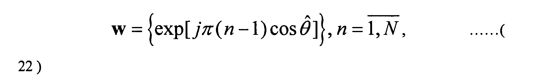
- The algorithm of determination of the direction MS signal arrival and is based on weigh coefficients vector of the reverse channel usage as well as the pilot signal accumulation and consists of the following.
- For each of L different directions i ,i=
1,L of the researched angular area: - M complex correlation pilot signal responses are determined at the output of the antenna array by the following:where u n ,n=

1,N represents complex correlation responses of a pilot signal at the output of the antenna array element correlators at a rate of J chips each, and - Non-coherent accumulation of M modules of complex correlation responses are determined by the following:

- During the summing of the modules of the complex correlation pilot signal responses at the output of the antenna array the number of additives is set, to be permanent or is chosen adaptively depending on signal fading frequency, in such a way that the full duration of non-coherent accumulation is determined over several fading periods. Otherwise, due to fade-out of useful signal, the error in the estimate of angle of arrival is possible.
- The value obtained from Equation 24 is normalized yielding:

- The discrete values of the antenna array pattern in the reverse channel are formed by
- The value obtained in Equation 26 is normalized yielding:

- The decision function is formed as the weighted sum of Equations (25) and (27)where a is a weight coefficient.

- The desired estimate and of average angular of MS signal arrival is determined by the position of decision function maximum in Equation (28), as given by:

- For the realization of such a method the second embodiment that is illustrated in Fig. 13 is used.
- As shown in Fig. 13, the proposed device contains N correlators 2.1 - 2.N, L decision function of the direction calculators 7.1 - 7.L, the first inputs of which are the inputs of the correlation responses of pilot signal of the antenna array elements and are connected to the outputs of the corresponding correlators 2.1- 2.N, a search block 13, a controller 14, antenna array weight coefficients in the reverse channel generator 5, a first normalization block 15, a second combiner 16, angle of signal arrival estimator 19, antenna array weight coefficients in the forward channel generator 6, and also scaling block 17 and second normalization block 18. The first inputs of correlators 2.1 - 2.N are the input signals and are connected to the device inputs. The second inputs of correlators 2.1 - 2.N are reference signals and are connected to the reference output of reference signal generator 1. The input of reference signal generator 1 is connected to the output of controller 14 that provides the synchronous functioning of the device. The first search block 13 is connected to the input of the device, the second input of search block 13 is connected to the output of controller 14, and the output of search block 13 outputs the search decision function and is connected to the input of controller 14. Each decision function direction calculator 7.1 - 7.L contains N-1 multipliers 8.2 - 8.N, first combiner 9, module calculator 10, complex direction coefficients 11, discrete values of the antenna array pattern in the reverse channel calculator 12, and reset combiner 23. First inputs of multipliers 8.2 - 8.N and first input of first combiner 9 are connected to outputs of correlators 2.1 - 2.N, outputs of multipliers 8.2 - 8.N are connected to the inputs of combiner 9, starting from the second and up to N. The output of combiner 9 is the complex correlation response of direction pilot signal at the output of the antenna array and is connected to the input of module calculator 10. The output of module calculator 10 is the module of direction pilot signal complex correlation response at the output of the antenna array and is connected to the first input of reset combiner 23, the second input of the reset combiner 23 which is a reset signal from controller 14. The output of reset controller 23 is the pilot signal combined correlation response at the output of the antenna array and the first output of each direction decision function calculation block 7.1 - 7.L, and is connected to the corresponding input of the first normalization 15.
- The first input of discrete values of the antenna array pattern in the reverse channel calculator 12 is the second input of each block of calculation of decision function of direction 7.1 - 7.L and is connected to the output of weight vector of antenna array in the reverse channel generator 5 generating at its output weight coefficients of antenna array elements in the reverse channel. Signal inputs of weight vector of the antenna array in the reverse channel generator 5 are connected to the input of the device. The second input of discrete values of the antenna array pattern in the reverse channel generator 12 and second inputs of multipliers 8.2 - 8.N are connected to the output of complex direction coefficients 11 which outputs the complex coefficients for the given direction.
- The output of discrete values of the antenna array pattern in the reverse channel calculator 12, which is the second output of decision function of direction calculators 7.1 - 7.L, and outputs values of antenna array pattern in the reverse channel, is connected to the corresponding input of second normalization block 18.
- The output of first normalization block 15, which outputs normalized modules of decision function of all L directions, is connected to the first input of second combiner 16. The output of second normalization block 18 outputs the normalized values of the antenna array pattern in the reverse channel of all L directions and is connected to the input of scaling block 17. The output of scaling block 17 outputs the weighted normalized values of the antenna array pattern in the reverse channel for L directions and is connected to the second input of second combiner 16. The output of second combiner 16 is the values of decision function for L directions and is connected to the input of angle of signal arrival estimator 19, the output of which is the estimate of the average angle of signal arrival and is connected to the input of weight coefficients of antenna array in the forward channel generator 6. The output of weight coefficients of antenna array in the forward channel generator 6 is the output of amplitude and phase coefficients of antenna array elements.
- The complex multipath signal supplied from outputs N of antenna array elements is fed to first (signal) inputs of correlators 2.1-2.N and outputs of weight coefficients in the reverse channel generator 5.
- At the same time the complex multipath signal supplied from the first antenna array element is fed to the input of search block 13. Search block 13 generates the decision function of path signal search in discrete time positions. This information of search block 13 is sent to controller 14, which compares the obtained values of the decision function with the threshold and determines time positions of path signals by determining which values exceed the threshold. In controller 14 the obtained values of the decision function for detected path signals are compared between each other, and time position of the path signal with the maximum value of the decision function is determined.
- From the control signal supplied from the output of controller 14, the reference signal corresponding to the path signal with the maximum power is fed from the output of reference signal generator 1, and to second inputs of correlators 2.1-2.N.
- In correlators 2.1-2.N complex correlation responses of the pilot signal of antenna array elements u n ,n=
1,N are generated on time intervals of J chip lengths. - The correlation responses of the pilot signal of antenna array elements are fed to first inputs of L decision function of direction calculators 7.1-7.L, namely to the first input of combiner 9, and to first inputs of corresponding (complex) multipliers 8.2-8.N. The number of L blocks of calculation of decision function 7.1-7.L is equal to the number of considered directions of the researched angular area.
- In weight vector of in the reverse channel generator 5, the complex weight coefficients of adaptive antenna array elements in the reverse channel are generated during reception of the subscriber signal according to one of algorithms proposed, for example, in R. A. Monzingo, T.U. Miler. Adaptive antenna arrays. /M.: Radio and communication, 1986, p. 77-90. These coefficients are fed to second inputs of decision function of direction calculators 7.1-7.L, and namely to first inputs of discrete values of antenna array pattern in the reverse channel calculators 12.
- Complex direction coefficients i 11 contains complex coefficients an ( i ),n=
1,N for the i -th direction, i=1,L These coefficients are calculated, for example, according to the algorithm proposed in Joseph C., Liberti, Jr., Bellcore, and Theodore S. Rappaport, "Smart Antennas for Wireless Communications" Prentice Hall PRT, 1999, p. 86-88. Complex direction coefficients an ( i ),n=1,N are fed to second inputs of corresponding (complex) multipliers 8.2-8.N and to second inputs of discrete values of antenna array pattern in the reverse channel calculator 12. - In this case according to Joseph C., Liberti, Jr. Bellcore Theodore S. Rappaport. Smart Antennas for Wireless Communications. Prentice Hall PRT, 1999, pp.. 86-88, complex coefficient a 1 ( i ) = 1, therefore the number of multipliers used in block of calculation of decision function of direction 7 is N-1.
- In each multiplier 8.2-8.N corresponding complex correlation responses of the pilot signal of antenna array elements are multiplied by complex coefficients an ( i ),n=
1,N of each direction. - Output signals of multipliers 8.2-8.N and complex correlation responses of the pilot signal of the first antenna array element supplied from the output of first correlator 2.1 are fed to inputs of combiner 9 where they are combined. A signal supplied from the output of combiner 9 corresponds to the complex correlation response of the pilot signal at the output of the antenna array for i direction.
- This signal is fed to the input of module calculator 10 where the square root of the sum of squares of the real and imaginary part of the signal is calculated. The output signal of module calculator 10 is equal to the module of complex correlation response of the pilot signal at the output of antenna array for i direction. This signal is supplied from the output of module calculator 10 to the first input of reset combiner 23, to the second input of which the control reset signal is supplied from controller 14.
- From the control reset signal in reset combiner 23 the non-coherent accumulation (combining) of M modules of complex correlation responses of the pilot signal at the output of the antenna array for i direction is performed.
- The number of M noncoherent components is set either constant or selected adaptively depending in the signal fading frequency so that the full duration of the non-coherent accumulation is determined for several fading periods.
- A signal supplied from the output of reset combiner 23 of each decision function of direction calculator 7.1-7.L is the combined correlation response of the pilot signal at the output of the antenna array Z( i ) of i direction, and is fed to the corresponding to input of normalization block 15. In normalization block 15 for L different directions the maximum combined correlation response of the pilot signal is determined at the output of antenna array by comparing the combined correlation responses of the pilot signal at the output of antenna array Z(i ) of different directions, and the normalized combined correlation responses of the pilot signal at the output of the antenna array are generated for L different directions. The normalization is performed by determining ratios of combined correlation responses of the pilot signal at the output of antenna array for L different directions, and the maximum combined correlation response. The obtained normalized signals for L different directions are fed to first inputs of combiner 16.
- In discrete values of antenna array pattern in the reverse channel calculator 12 for each of L different directions i ,i=
1,L of the researched angular area, the values of the antenna array pattern in the reverse channel are generated according, " Smart Antennas for Wireless Communications", as indicated above, and which are transmitted to inputs of normalization block 18. - In normalization block 18 for L different directions the maximum value of the antenna array pattern in the reverse channel is determined by comparing values of the antenna array pattern in the reverse channel of different directions with each other, and normalized values of the antenna array pattern in the reverse channel are generated for L different directions. The normalization is performed by determining the ratio of values of the antenna array pattern in the reverse channel for L different directions to the maximum value. The obtained normalized values of the antenna array pattern in the reverse channel for L different directions are fed to the input of scaling block 17. Scaling block 17 generates the weighted values of the normalized antenna array pattern in the reverse channel for L different directions by multiplying values of the normalized antenna array pattern by a weight coefficient that is fed to the second input of combiner 16. The decision function is generated at the output of combiner 16 for L different directions i ,i=
1,L of the researched angular area performing the combining of normalized combined correlation responses of the pilot signal at the output of antenna array and weighted values of the antenna array pattern in the reverse channel. The signal of the decision function is sent to angle of signal arrival estimator 19, in which the maximum value of the decision function is determined by comparing values of the decision function for L different directions i ,i=1,L of the researched angular area to each other. The searched estimate and of the average angle of signal arrival in the reverse channel is determined by the position of direction of the decision function maximum. - Estimate and of the average angle of signal arrival in the reverse channel is fed to the input of weight vector of the antenna array in the foward channel generator 6, in which, for example, according to the algorithm discussed above, phase coefficients of antenna array elements are determined using the generated estimate of the average angle of arrival of the signal taking into account the geometry of the antenna array. Amplitude coefficients of antenna array elements are set equal to each other. Finally the complex weight coefficient vector of the antenna array in the forward channel, for example, for the half-wave equidistant antenna array is determined as follows :
- The obtained complex weight coefficients of antenna array elements are utilized to transmit the signal to the subscriber in the forward channel.
- Although the preferred embodiments of the present invention have been disclosed for illustrative purposes, those skilled in the art will appreciate that various modifications, additions and substitutions are possible, without departing from the scope and spirit of the invention as disclosed in the accompanying claims.
Claims (25)
- A method for forming a forward channel pattern in a base station of a communication system equipped with an antenna array, comprising the steps of:generating complex correlation responses to a signal received by the antenna array in association with L different directions, respectively;calculating discrete values of an antenna pattern in a reverse channel in association with the L different directions, respectively;combining the generated complex correlation responses with the discrete values of the antenna pattern associated therewith; andgenerating weight vectors of the antenna array in a forward channel.
- The method of claim 1, wherein the received signal is a pilot signal.
- The method of claim 1, wherein the step of generating the complex correlation responses comprises the steps of:generating complex correlation pilot signal responses to the pilot signal received through one of elements of the antenna array;multiplying the generated pilot signal responses by complex direction coefficients predetermined for the antenna array elements in association with the L different directions, respectively; andcombining the results of the multiplication, thereby generating the complex correlation responses respectively associated with the L different directions.
- The method of claim 3, further comprising the step of non-coherently accumulating the complex correlation response associated with each of the L different directions by a predetermined number.
- The method of claim 3, further comprising the step of normalizing the complex correlation response associated with each of the L different directions.
- The method of claim 1, wherein the step of calculating the discrete values of the antenna pattern comprises the steps of:generating complex weight coefficients for elements of the antenna array in the reverse channel; andcalculating the discrete values of the antenna pattern, based on the generated complex weight coefficients and complex direction coefficients respectively predetermined for the antenna array elements, in association with the L different directions, respectively.
- The method of claim 6, further comprising the steps of:normalizing the discrete values of the antenna pattern respectively associated with the L different directions; andscaling the normalized discrete values of the antenna pattern.
- The method of claim 1, wherein the step of generating the weight vectors comprises the steps of:combining the generated complex correlation responses with the discrete values of the antenna pattern associated therewith, thereby generating decision functions in association with the L different directions, respectively;estimating, in association with the L different directions, angles of signal arrival at each of which an associated one of the generated decision function has a maximum value; anddetermining amplitude and phase coefficients of elements of the antenna array, based on the estimated angles of signal arrival, respectively.
- The method of claim 8, further comprising the step of estimating respective averages of the estimated signal arrival angles so that the average angles are used for the determination of the amplitude and phase coefficients.
- The method of claim 9, wherein the step of determining the amplitude and phase coefficients comprises the steps of:estimating top and bottom boundaries of angle signal areas for respective averaged estimate distribution vectors of the estimated signal arrival angles, thereby estimating the average signal arrival angles;determining the phase coefficients based on the estimated average signal arrival angles, respectively, while taking into consideration a geometry of the antenna array;forming a correlation matrix of the antenna array elements based on the estimated top and bottom boundaries of the angle signal areas;obtaining a bottom triangular matrix from the formed correlation matrix; anddetermining the amplitude coefficients of the antenna array elements based on the obtained bottom triangular matrix and the determined phase coefficients.
- The method of claim 10, wherein the ratio of the amplitude coefficient of the antenna array element transmitting the pilot signal to the amplitude coefficient of each of the remaining antenna array elements is 1 : µ, where µ is a maximum value of an average power ratio between coherent and non-coherent components of the received signal, the value being not more than a predetermined value.
- The method of claim 10, further comprising the step of compensating for the top and bottom boundaries of the angle signal areas.
- An apparatus for forming a forward channel pattern in a base station of a communication system equipped with an antenna array, comprising:a calculation block for generating complex correlation responses to a signal received by the antenna array in association with L different directions, respectively, and calculating discrete values of the antenna pattern in a reverse channel;a combiner for combining the generated complex correlation responses with the discrete values of the antenna pattern associated therewith, thereby generating decision functions, respectively; anda weight vector generator for generating weight vectors of the antenna array in a forward channel, based on the generated decision functions, respectively.
- The apparatus of claim 13, wherein the received signal is a pilot signal.
- The apparatus of claim 14, wherein the calculation block comprises:multipliers for multiplying complex correlation pilot signal responses to the pilot signal received through one of elements of the antenna array by complex direction coefficients predetermined for the antenna array elements, in association with the L different directions, respectively;a combiner for combining the results of the multiplication, thereby generating the complex correlation responses respectively associated with the L different directions; anda block for receiving respective complex weight coefficients for the antenna array elements in the reverse channel and complex direction coefficients respectively predetermined for the antenna array elements, in association with the L different directions, thereby calculating the discrete values of an antenna pattern, respectively.
- The apparatus of claim 15, further comprising:correlators for generating the complex correlation pilot signal responses to the received pilot signal; anda block for generating the complex weight coefficients for the antenna array elements in the reverse channel.
- The apparatus of claim 15, further comprising:a reset combiner for resetting an output of the complex correlation response generating combiner in order to non-coherently accumulate the complex correlation response associated with each of the L different directions by a predetermined number.
- The apparatus of claim 16, further comprising:a normalization block for normalizing the complex correlation response associated with each of the L different directions.
- The apparatus of claim 16, further comprising:a normalization block for normalizing the discrete values of the antenna pattern respectively associated with the L different directions; anda scaling block for scaling the normalized discrete values of the antenna pattern.
- The apparatus of claim 13, wherein the weight vector generator determines amplitude and phase coefficients of elements of the antenna array, based on angles of signal arrival at each of which an associated one of the generated decision function has a maximum value, in association with the L different directions, respectively.
- The apparatus of claim 20, further comprising:a block for estimating, in association with the L different directions, the angles of signal arrival at each of which an associated one of the generated decision function has a maximum value, respectively; anda block for estimating respective averages of the estimated signal arrival angles so that the average angles are used for the determination of the amplitude and phase coefficients.
- The apparatus of claim 21, wherein the average signal arrival angle estimating block performs the estimation of the average signal arrival angles by estimating top and bottom boundaries of angle signal areas for respective averaged estimate distribution vectors of the estimated signal arrival angles, respectively.
- The apparatus of claim 22, wherein the weight vector generator performs operations of:determining the phase coefficients based on the estimated average signal arrival angles, respectively, while taking into consideration a geometry of the antenna array;forming a correlation matrix of the antenna array elements based on the estimated top and bottom boundaries of the angle signal areas;obtaining a bottom triangular matrix from the formed correlation matrix; anddetermining the amplitude coefficients of the antenna array elements based on the obtained bottom triangular matrix and the determined phase coefficients.
- The apparatus of claim 23, wherein the ratio of the amplitude coefficient of the antenna array element transmitting the pilot signal to the amplitude coefficient of each of the remaining antenna array elements is 1 : µ, where µ is a maximum value of an average power ratio between coherent and non-coherent components of the received signal, the value being not more than a predetermined value.
- The apparatus of claim 23, wherein the top and bottom boundaries of the angle signal areas are compensated for.
Applications Claiming Priority (2)
| Application Number | Priority Date | Filing Date | Title |
|---|---|---|---|
| RU2002103215/09A RU2237379C2 (en) | 2002-02-08 | 2002-02-08 | Method and device for shaping directivity pattern of base-station adaptive antenna array |
| RU2002103215 | 2002-02-08 |
Publications (3)
| Publication Number | Publication Date |
|---|---|
| EP1335504A2 true EP1335504A2 (en) | 2003-08-13 |
| EP1335504A3 EP1335504A3 (en) | 2005-07-27 |
| EP1335504B1 EP1335504B1 (en) | 2006-11-29 |
Family
ID=27607293
Family Applications (1)
| Application Number | Title | Priority Date | Filing Date |
|---|---|---|---|
| EP03002622A Expired - Fee Related EP1335504B1 (en) | 2002-02-08 | 2003-02-10 | Pattern forming method and device for an adaptive antenna array of a base station |
Country Status (6)
| Country | Link |
|---|---|
| US (1) | US7376094B2 (en) |
| EP (1) | EP1335504B1 (en) |
| KR (1) | KR100575923B1 (en) |
| CN (1) | CN100423363C (en) |
| DE (1) | DE60309942T2 (en) |
| RU (1) | RU2237379C2 (en) |
Cited By (34)
| Publication number | Priority date | Publication date | Assignee | Title |
|---|---|---|---|---|
| WO2005029728A1 (en) * | 2003-09-19 | 2005-03-31 | Intel Corporation | Wireless signal processing methods and apparatuses including directions of arrival estimation |
| US7453946B2 (en) | 2003-09-03 | 2008-11-18 | Intel Corporation | Communication system and method for channel estimation and beamforming using a multi-element array antenna |
| US8045512B2 (en) | 2005-10-27 | 2011-10-25 | Qualcomm Incorporated | Scalable frequency band operation in wireless communication systems |
| US8098568B2 (en) | 2000-09-13 | 2012-01-17 | Qualcomm Incorporated | Signaling method in an OFDM multiple access system |
| US8446892B2 (en) | 2005-03-16 | 2013-05-21 | Qualcomm Incorporated | Channel structures for a quasi-orthogonal multiple-access communication system |
| US8462859B2 (en) | 2005-06-01 | 2013-06-11 | Qualcomm Incorporated | Sphere decoding apparatus |
| US8477684B2 (en) | 2005-10-27 | 2013-07-02 | Qualcomm Incorporated | Acknowledgement of control messages in a wireless communication system |
| US8565194B2 (en) | 2005-10-27 | 2013-10-22 | Qualcomm Incorporated | Puncturing signaling channel for a wireless communication system |
| US8582548B2 (en) | 2005-11-18 | 2013-11-12 | Qualcomm Incorporated | Frequency division multiple access schemes for wireless communication |
| US8582509B2 (en) | 2005-10-27 | 2013-11-12 | Qualcomm Incorporated | Scalable frequency band operation in wireless communication systems |
| US8599945B2 (en) | 2005-06-16 | 2013-12-03 | Qualcomm Incorporated | Robust rank prediction for a MIMO system |
| US8611284B2 (en) | 2005-05-31 | 2013-12-17 | Qualcomm Incorporated | Use of supplemental assignments to decrement resources |
| US8693405B2 (en) | 2005-10-27 | 2014-04-08 | Qualcomm Incorporated | SDMA resource management |
| US8787347B2 (en) | 2005-08-24 | 2014-07-22 | Qualcomm Incorporated | Varied transmission time intervals for wireless communication system |
| US8831607B2 (en) | 2006-01-05 | 2014-09-09 | Qualcomm Incorporated | Reverse link other sector communication |
| US8879511B2 (en) | 2005-10-27 | 2014-11-04 | Qualcomm Incorporated | Assignment acknowledgement for a wireless communication system |
| US8885628B2 (en) | 2005-08-08 | 2014-11-11 | Qualcomm Incorporated | Code division multiplexing in a single-carrier frequency division multiple access system |
| US8917654B2 (en) | 2005-04-19 | 2014-12-23 | Qualcomm Incorporated | Frequency hopping design for single carrier FDMA systems |
| US9088384B2 (en) | 2005-10-27 | 2015-07-21 | Qualcomm Incorporated | Pilot symbol transmission in wireless communication systems |
| US9130810B2 (en) | 2000-09-13 | 2015-09-08 | Qualcomm Incorporated | OFDM communications methods and apparatus |
| US9137822B2 (en) | 2004-07-21 | 2015-09-15 | Qualcomm Incorporated | Efficient signaling over access channel |
| US9136974B2 (en) | 2005-08-30 | 2015-09-15 | Qualcomm Incorporated | Precoding and SDMA support |
| US9143305B2 (en) | 2005-03-17 | 2015-09-22 | Qualcomm Incorporated | Pilot signal transmission for an orthogonal frequency division wireless communication system |
| US9144060B2 (en) | 2005-10-27 | 2015-09-22 | Qualcomm Incorporated | Resource allocation for shared signaling channels |
| US9148256B2 (en) | 2004-07-21 | 2015-09-29 | Qualcomm Incorporated | Performance based rank prediction for MIMO design |
| US9172453B2 (en) | 2005-10-27 | 2015-10-27 | Qualcomm Incorporated | Method and apparatus for pre-coding frequency division duplexing system |
| US9179319B2 (en) | 2005-06-16 | 2015-11-03 | Qualcomm Incorporated | Adaptive sectorization in cellular systems |
| US9210651B2 (en) | 2005-10-27 | 2015-12-08 | Qualcomm Incorporated | Method and apparatus for bootstraping information in a communication system |
| US9209956B2 (en) | 2005-08-22 | 2015-12-08 | Qualcomm Incorporated | Segment sensitive scheduling |
| US9225416B2 (en) | 2005-10-27 | 2015-12-29 | Qualcomm Incorporated | Varied signaling channels for a reverse link in a wireless communication system |
| US9225488B2 (en) | 2005-10-27 | 2015-12-29 | Qualcomm Incorporated | Shared signaling channel |
| US9307544B2 (en) | 2005-04-19 | 2016-04-05 | Qualcomm Incorporated | Channel quality reporting for adaptive sectorization |
| US9520972B2 (en) | 2005-03-17 | 2016-12-13 | Qualcomm Incorporated | Pilot signal transmission for an orthogonal frequency division wireless communication system |
| US9660776B2 (en) | 2005-08-22 | 2017-05-23 | Qualcomm Incorporated | Method and apparatus for providing antenna diversity in a wireless communication system |
Families Citing this family (31)
| Publication number | Priority date | Publication date | Assignee | Title |
|---|---|---|---|---|
| KR100428709B1 (en) * | 2001-08-17 | 2004-04-27 | 한국전자통신연구원 | Apparatus for Forward Beamforming using Feedback of Multipath Information and Method Thereof |
| US7054664B2 (en) * | 2003-10-30 | 2006-05-30 | Lucent Technologies Inc. | Method and apparatus for providing user specific downlink beamforming in a fixed beam network |
| US9246560B2 (en) | 2005-03-10 | 2016-01-26 | Qualcomm Incorporated | Systems and methods for beamforming and rate control in a multi-input multi-output communication systems |
| US9154211B2 (en) | 2005-03-11 | 2015-10-06 | Qualcomm Incorporated | Systems and methods for beamforming feedback in multi antenna communication systems |
| US9461859B2 (en) | 2005-03-17 | 2016-10-04 | Qualcomm Incorporated | Pilot signal transmission for an orthogonal frequency division wireless communication system |
| US9184870B2 (en) | 2005-04-01 | 2015-11-10 | Qualcomm Incorporated | Systems and methods for control channel signaling |
| US7088289B1 (en) * | 2005-04-05 | 2006-08-08 | Nokia Corporation | Antenna adaptation method, communication terminal, device; module and computer program product |
| US20060256882A1 (en) * | 2005-05-13 | 2006-11-16 | Interdigital Technology Corporation | Method and apparatus for adjusting transmission parameters to improve a communication link |
| US8102830B2 (en) * | 2005-12-16 | 2012-01-24 | Samsung Electronics Co., Ltd. | MIMO radio communication apparatus and method |
| US8135026B2 (en) | 2006-01-05 | 2012-03-13 | Qualcomm, Incorporated | Disjoint and common link operation in a wireless communication system |
| US20070281632A1 (en) * | 2006-06-05 | 2007-12-06 | Ada Shuk Yan Poon | Angular domain signal processing techniques |
| US8542589B2 (en) | 2006-06-05 | 2013-09-24 | Qualcomm Incorporated | Method and apparatus for providing beamforming feedback in wireless communication systems |
| WO2008034458A1 (en) * | 2006-09-22 | 2008-03-27 | Telecom Italia S.P.A. | Method and system for syntesizing array antennas |
| JP4823261B2 (en) * | 2008-03-19 | 2011-11-24 | 株式会社東芝 | Weight calculation method, weight calculation device, adaptive array antenna, and radar device |
| JP2009246517A (en) * | 2008-03-28 | 2009-10-22 | Kyocera Corp | Base station apparatus and channel allocation method |
| CN103931112B (en) * | 2011-09-15 | 2017-03-08 | 三星电子株式会社 | For carrying out the apparatus and method of beam selection in Wave beam forming wireless communication system |
| WO2013175774A1 (en) | 2012-05-22 | 2013-11-28 | パナソニック株式会社 | Transmission method, reception method, transmitter, and receiver |
| RU2480869C1 (en) * | 2012-09-13 | 2013-04-27 | Петр Николаевич Башлы | Method for generation of contour directivity diagram of antenna array |
| KR102207844B1 (en) * | 2014-07-08 | 2021-01-26 | 한국전자통신연구원 | System, method, and computer-readable medium for estimating direction of arrival of a signal incident on at least one antenna array |
| RU2567120C1 (en) * | 2014-07-16 | 2015-11-10 | Федеральное государственное унитарное предприятие "Ростовский-на-Дону научно-исследовательский институт радиосвязи" (ФГУП "РНИИРС") | Method of forming compensation beam pattern in flat electronically controlled-beam antenna array |
| US10205491B2 (en) * | 2015-09-28 | 2019-02-12 | Futurewei Technologies, Inc. | System and method for large scale multiple input multiple output communications |
| CN106680789B (en) * | 2016-12-19 | 2020-01-07 | 四川九洲电器集团有限责任公司 | Angle measurement function verification method and verification system of single-pulse angle measurement equipment |
| RU2650095C1 (en) * | 2017-04-26 | 2018-04-06 | Федеральное государственное бюджетное учреждение "Центральный научно-исследовательский институт Войск воздушно-космической обороны Минобороны России (ФГБУ "ЦНИИ ВВКО Минобороны России") | Method for synthesis of a multi-beam self-focusing adaptive antenna arrays by using a parametric model of signals of radiation sources |
| RU2650096C1 (en) * | 2017-04-26 | 2018-04-06 | Федеральное государственное бюджетное учреждение "Центральный научно-исследовательский институт Войск воздушно-космической обороны Минобороны России (ФГБУ "ЦНИИ ВВКО Минобороны России") | Method of the multi-beam adaptive antenna array beam pattern generating using the input signal spatial frequencies spectrum parametric model |
| RU2657355C1 (en) * | 2017-07-20 | 2018-06-13 | Саркис Манукович Казарян | Method of the virtual phased antenna array creating |
| RU2659613C1 (en) * | 2017-09-11 | 2018-07-03 | Федеральное государственное бюджетное учреждение "Центральный научно-исследовательский институт Войск воздушно-космической обороны" Минобороны России (ФГБУ "ЦНИИ ВВКО" Минобороны России) | Method of synthesizing of a multi-beam self-focusing adaptive antenna array using a parametric model of the spatial frequency spectrum of emission sources signals |
| RU2659608C1 (en) * | 2017-09-26 | 2018-07-03 | Федеральное государственное бюджетное учреждение "Центральный научно-исследовательский институт Войск воздушно-космической обороны Минобороны России (ФГБУ "ЦНИИ ВВКО Минобороны России") | Method for synthesis of a multi-beam self-focusing adaptive antenna arrays by using a parametric correlation matrix model of a received signal |
| US10330770B2 (en) * | 2017-11-09 | 2019-06-25 | Cisco Technology, Inc. | Channel estimation in OFDMA for switched antenna array based angle-of-arrival location |
| KR102455635B1 (en) * | 2018-05-25 | 2022-10-17 | 삼성전자주식회사 | Method and apparatus for determining object direction |
| US11211994B2 (en) * | 2020-04-06 | 2021-12-28 | Samsung Electronics Co., Ltd. | Angular sparse channel recovery using history measurements |
| US20220271852A1 (en) * | 2021-02-22 | 2022-08-25 | Samsung Electronics Co., Ltd. | Multiple antenna channel tracking under practical impairment |
Citations (2)
| Publication number | Priority date | Publication date | Assignee | Title |
|---|---|---|---|---|
| US6108565A (en) * | 1997-09-15 | 2000-08-22 | Adaptive Telecom, Inc. | Practical space-time radio method for CDMA communication capacity enhancement |
| WO2001091325A1 (en) * | 2000-05-25 | 2001-11-29 | Siemens Aktiengesellschaft | Method for controlling the formation of a downlink beam |
Family Cites Families (19)
| Publication number | Priority date | Publication date | Assignee | Title |
|---|---|---|---|---|
| US5828658A (en) | 1991-12-12 | 1998-10-27 | Arraycomm, Inc. | Spectrally efficient high capacity wireless communication systems with spatio-temporal processing |
| GB2309591B (en) * | 1996-01-27 | 1999-08-04 | Motorola Ltd | Apparatus and method for adaptive beamforming |
| CN1179856A (en) * | 1996-01-27 | 1998-04-22 | 摩托罗拉有限公司 | Apparatus and method for adaptive beamforming in antenna array |
| WO1998020411A1 (en) * | 1996-11-08 | 1998-05-14 | Neomedia Technologies, Inc. | Automatic access of electronic information through machine-readable codes on printed documents |
| US6122260A (en) | 1996-12-16 | 2000-09-19 | Civil Telecommunications, Inc. | Smart antenna CDMA wireless communication system |
| BR9812816A (en) * | 1997-09-15 | 2000-08-08 | Adaptive Telecom Inc | Processes for wireless communication, and to efficiently determine a space channel of the mobile unit in a wireless communication system at the base station, and cdma base station |
| JP3716398B2 (en) * | 1998-03-05 | 2005-11-16 | 富士通株式会社 | Direction-of-arrival estimation method using array antenna and DS-CDMA receiver using the method |
| JP4169884B2 (en) * | 1999-09-24 | 2008-10-22 | 富士通株式会社 | Communication device using adaptive antenna |
| JP3562420B2 (en) * | 2000-02-10 | 2004-09-08 | 日本電気株式会社 | Adaptive antenna device |
| JP4310022B2 (en) * | 2000-04-17 | 2009-08-05 | 国立大学法人横浜国立大学 | Array antenna calibration method and calibration apparatus |
| GB2363256B (en) * | 2000-06-07 | 2004-05-12 | Motorola Inc | Adaptive antenna array and method of controlling operation thereof |
| JP2002111564A (en) * | 2000-09-27 | 2002-04-12 | Matsushita Electric Ind Co Ltd | Base station device and radio transmission method |
| JP2002135185A (en) * | 2000-10-19 | 2002-05-10 | Hitachi Kokusai Electric Inc | Receiver |
| AU2002219506A1 (en) * | 2000-12-21 | 2002-07-01 | Matsushita Electric Industrial Co., Ltd. | Base station device |
| US6483459B1 (en) * | 2001-04-05 | 2002-11-19 | Neoreach, Inc. | Direction of arrival angle tracking algorithm for smart antennas |
| DE60209051T2 (en) * | 2001-04-20 | 2006-10-26 | Lg Electronics Inc. | Location determination of a mobile communication terminal based on a combination of measurements of signals exchanged between the mobile communication terminal and base stations |
| KR100428709B1 (en) * | 2001-08-17 | 2004-04-27 | 한국전자통신연구원 | Apparatus for Forward Beamforming using Feedback of Multipath Information and Method Thereof |
| JP2003110476A (en) * | 2001-09-27 | 2003-04-11 | Matsushita Electric Ind Co Ltd | Radio receiver and directional reception method |
| JP4299083B2 (en) * | 2003-09-09 | 2009-07-22 | 株式会社エヌ・ティ・ティ・ドコモ | Wireless communication apparatus and wireless communication method |
-
2002
- 2002-02-08 RU RU2002103215/09A patent/RU2237379C2/en not_active IP Right Cessation
-
2003
- 2003-02-08 CN CNB031226604A patent/CN100423363C/en not_active Expired - Fee Related
- 2003-02-08 KR KR1020030008057A patent/KR100575923B1/en not_active IP Right Cessation
- 2003-02-10 DE DE60309942T patent/DE60309942T2/en not_active Expired - Lifetime
- 2003-02-10 EP EP03002622A patent/EP1335504B1/en not_active Expired - Fee Related
- 2003-02-10 US US10/361,650 patent/US7376094B2/en active Active
Patent Citations (2)
| Publication number | Priority date | Publication date | Assignee | Title |
|---|---|---|---|---|
| US6108565A (en) * | 1997-09-15 | 2000-08-22 | Adaptive Telecom, Inc. | Practical space-time radio method for CDMA communication capacity enhancement |
| WO2001091325A1 (en) * | 2000-05-25 | 2001-11-29 | Siemens Aktiengesellschaft | Method for controlling the formation of a downlink beam |
Cited By (56)
| Publication number | Priority date | Publication date | Assignee | Title |
|---|---|---|---|---|
| US10313069B2 (en) | 2000-09-13 | 2019-06-04 | Qualcomm Incorporated | Signaling method in an OFDM multiple access system |
| US9130810B2 (en) | 2000-09-13 | 2015-09-08 | Qualcomm Incorporated | OFDM communications methods and apparatus |
| US8098568B2 (en) | 2000-09-13 | 2012-01-17 | Qualcomm Incorporated | Signaling method in an OFDM multiple access system |
| US8098569B2 (en) | 2000-09-13 | 2012-01-17 | Qualcomm Incorporated | Signaling method in an OFDM multiple access system |
| US11032035B2 (en) | 2000-09-13 | 2021-06-08 | Qualcomm Incorporated | Signaling method in an OFDM multiple access system |
| US9426012B2 (en) | 2000-09-13 | 2016-08-23 | Qualcomm Incorporated | Signaling method in an OFDM multiple access system |
| US7453946B2 (en) | 2003-09-03 | 2008-11-18 | Intel Corporation | Communication system and method for channel estimation and beamforming using a multi-element array antenna |
| US8165233B2 (en) | 2003-09-03 | 2012-04-24 | Intel Corporation | Multi-element antenna beamforming in a wireless access network |
| US6987482B2 (en) | 2003-09-19 | 2006-01-17 | Intel Corporation | Wireless signal processing methods and apparatuses including directions of arrival estimation |
| KR100870287B1 (en) * | 2003-09-19 | 2008-11-25 | 인텔 코오퍼레이션 | Wireless signal processing methods and apparatuses including directions of arrival estimation |
| CN1853360B (en) * | 2003-09-19 | 2010-05-12 | 英特尔公司 | Wireless signal processing methods and apparatuses including directions of arrival estimation |
| WO2005029728A1 (en) * | 2003-09-19 | 2005-03-31 | Intel Corporation | Wireless signal processing methods and apparatuses including directions of arrival estimation |
| US11039468B2 (en) | 2004-07-21 | 2021-06-15 | Qualcomm Incorporated | Efficient signaling over access channel |
| US10517114B2 (en) | 2004-07-21 | 2019-12-24 | Qualcomm Incorporated | Efficient signaling over access channel |
| US10237892B2 (en) | 2004-07-21 | 2019-03-19 | Qualcomm Incorporated | Efficient signaling over access channel |
| US10194463B2 (en) | 2004-07-21 | 2019-01-29 | Qualcomm Incorporated | Efficient signaling over access channel |
| US10849156B2 (en) | 2004-07-21 | 2020-11-24 | Qualcomm Incorporated | Efficient signaling over access channel |
| US9148256B2 (en) | 2004-07-21 | 2015-09-29 | Qualcomm Incorporated | Performance based rank prediction for MIMO design |
| US9137822B2 (en) | 2004-07-21 | 2015-09-15 | Qualcomm Incorporated | Efficient signaling over access channel |
| US8547951B2 (en) | 2005-03-16 | 2013-10-01 | Qualcomm Incorporated | Channel structures for a quasi-orthogonal multiple-access communication system |
| US8446892B2 (en) | 2005-03-16 | 2013-05-21 | Qualcomm Incorporated | Channel structures for a quasi-orthogonal multiple-access communication system |
| US9520972B2 (en) | 2005-03-17 | 2016-12-13 | Qualcomm Incorporated | Pilot signal transmission for an orthogonal frequency division wireless communication system |
| US9143305B2 (en) | 2005-03-17 | 2015-09-22 | Qualcomm Incorporated | Pilot signal transmission for an orthogonal frequency division wireless communication system |
| US9307544B2 (en) | 2005-04-19 | 2016-04-05 | Qualcomm Incorporated | Channel quality reporting for adaptive sectorization |
| US8917654B2 (en) | 2005-04-19 | 2014-12-23 | Qualcomm Incorporated | Frequency hopping design for single carrier FDMA systems |
| US9408220B2 (en) | 2005-04-19 | 2016-08-02 | Qualcomm Incorporated | Channel quality reporting for adaptive sectorization |
| US8611284B2 (en) | 2005-05-31 | 2013-12-17 | Qualcomm Incorporated | Use of supplemental assignments to decrement resources |
| US8462859B2 (en) | 2005-06-01 | 2013-06-11 | Qualcomm Incorporated | Sphere decoding apparatus |
| US9179319B2 (en) | 2005-06-16 | 2015-11-03 | Qualcomm Incorporated | Adaptive sectorization in cellular systems |
| US8599945B2 (en) | 2005-06-16 | 2013-12-03 | Qualcomm Incorporated | Robust rank prediction for a MIMO system |
| US9693339B2 (en) | 2005-08-08 | 2017-06-27 | Qualcomm Incorporated | Code division multiplexing in a single-carrier frequency division multiple access system |
| US8885628B2 (en) | 2005-08-08 | 2014-11-11 | Qualcomm Incorporated | Code division multiplexing in a single-carrier frequency division multiple access system |
| US9246659B2 (en) | 2005-08-22 | 2016-01-26 | Qualcomm Incorporated | Segment sensitive scheduling |
| US9240877B2 (en) | 2005-08-22 | 2016-01-19 | Qualcomm Incorporated | Segment sensitive scheduling |
| US9860033B2 (en) | 2005-08-22 | 2018-01-02 | Qualcomm Incorporated | Method and apparatus for antenna diversity in multi-input multi-output communication systems |
| US9209956B2 (en) | 2005-08-22 | 2015-12-08 | Qualcomm Incorporated | Segment sensitive scheduling |
| US9660776B2 (en) | 2005-08-22 | 2017-05-23 | Qualcomm Incorporated | Method and apparatus for providing antenna diversity in a wireless communication system |
| US8787347B2 (en) | 2005-08-24 | 2014-07-22 | Qualcomm Incorporated | Varied transmission time intervals for wireless communication system |
| US9136974B2 (en) | 2005-08-30 | 2015-09-15 | Qualcomm Incorporated | Precoding and SDMA support |
| US8879511B2 (en) | 2005-10-27 | 2014-11-04 | Qualcomm Incorporated | Assignment acknowledgement for a wireless communication system |
| US9172453B2 (en) | 2005-10-27 | 2015-10-27 | Qualcomm Incorporated | Method and apparatus for pre-coding frequency division duplexing system |
| US8693405B2 (en) | 2005-10-27 | 2014-04-08 | Qualcomm Incorporated | SDMA resource management |
| US8045512B2 (en) | 2005-10-27 | 2011-10-25 | Qualcomm Incorporated | Scalable frequency band operation in wireless communication systems |
| US9088384B2 (en) | 2005-10-27 | 2015-07-21 | Qualcomm Incorporated | Pilot symbol transmission in wireless communication systems |
| US9225488B2 (en) | 2005-10-27 | 2015-12-29 | Qualcomm Incorporated | Shared signaling channel |
| US9225416B2 (en) | 2005-10-27 | 2015-12-29 | Qualcomm Incorporated | Varied signaling channels for a reverse link in a wireless communication system |
| US8842619B2 (en) | 2005-10-27 | 2014-09-23 | Qualcomm Incorporated | Scalable frequency band operation in wireless communication systems |
| US9210651B2 (en) | 2005-10-27 | 2015-12-08 | Qualcomm Incorporated | Method and apparatus for bootstraping information in a communication system |
| US9144060B2 (en) | 2005-10-27 | 2015-09-22 | Qualcomm Incorporated | Resource allocation for shared signaling channels |
| US8582509B2 (en) | 2005-10-27 | 2013-11-12 | Qualcomm Incorporated | Scalable frequency band operation in wireless communication systems |
| US8477684B2 (en) | 2005-10-27 | 2013-07-02 | Qualcomm Incorporated | Acknowledgement of control messages in a wireless communication system |
| US8565194B2 (en) | 2005-10-27 | 2013-10-22 | Qualcomm Incorporated | Puncturing signaling channel for a wireless communication system |
| US10805038B2 (en) | 2005-10-27 | 2020-10-13 | Qualcomm Incorporated | Puncturing signaling channel for a wireless communication system |
| US8582548B2 (en) | 2005-11-18 | 2013-11-12 | Qualcomm Incorporated | Frequency division multiple access schemes for wireless communication |
| US8681764B2 (en) | 2005-11-18 | 2014-03-25 | Qualcomm Incorporated | Frequency division multiple access schemes for wireless communication |
| US8831607B2 (en) | 2006-01-05 | 2014-09-09 | Qualcomm Incorporated | Reverse link other sector communication |
Also Published As
| Publication number | Publication date |
|---|---|
| US7376094B2 (en) | 2008-05-20 |
| EP1335504B1 (en) | 2006-11-29 |
| KR20030067598A (en) | 2003-08-14 |
| DE60309942T2 (en) | 2007-09-20 |
| EP1335504A3 (en) | 2005-07-27 |
| DE60309942D1 (en) | 2007-01-11 |
| RU2237379C2 (en) | 2004-09-27 |
| CN100423363C (en) | 2008-10-01 |
| US20030152099A1 (en) | 2003-08-14 |
| KR100575923B1 (en) | 2006-05-02 |
| CN1445885A (en) | 2003-10-01 |
Similar Documents
| Publication | Publication Date | Title |
|---|---|---|
| EP1335504B1 (en) | Pattern forming method and device for an adaptive antenna array of a base station | |
| EP1345337B1 (en) | Adaptive antenna base station apparatus with direction of arrival estimation | |
| US6347234B1 (en) | Practical space-time radio method for CDMA communication capacity enhancement | |
| US7162210B2 (en) | Method and device of antenna pattern forming | |
| US6108565A (en) | Practical space-time radio method for CDMA communication capacity enhancement | |
| Choi et al. | A novel adaptive beamforming algorithm for a smart antenna system in a CDMA mobile communication environment | |
| CN1957540B (en) | Impairment correlation estimator in a spread spectrum system and estimation method | |
| CN100544231C (en) | Smart antenna implementation method and smart antenna based on software radio are realized system | |
| US7088956B2 (en) | Path search circuit, radio receiver and radio transmitter, utilizing a directional beam | |
| CN100499398C (en) | Method and apparatus for realizing intelligent antenna of broadband CDMA system | |
| JP3738705B2 (en) | Adaptive antenna device | |
| JP3482810B2 (en) | Array antenna and its design method, signal processing method with array antenna, and signal transmitting / receiving apparatus and method using the same | |
| EP1253434A1 (en) | Method for estimating a direction of arrival | |
| SE9904003D0 (en) | Hardware-efficient demodulator for CDMA adaptive antenna array systems | |
| EP0992813A2 (en) | Radio wave arrival direction estimating antenna apparatus | |
| KR20020066388A (en) | Adaptive antenna receiving apparatus | |
| US20050185703A1 (en) | Receiving apparatus | |
| AU7203100A (en) | Code division multiple access system and method of operation with improved signal acquisition and processing | |
| KR100375826B1 (en) | Weight calculation unit for forward beamforming in a direct spread CDMA base station system using an array antenna, system for forward beamforming using it and method thereof | |
| EP1365521B1 (en) | Path timing detection method for and adaptive array antenna system | |
| JP2006041562A (en) | Base station device and radio receiving method | |
| CN101084633B (en) | Multipath searcher, refinement treatment unit and method for direction of arrival estimation using multipath searcher | |
| CN101133659B (en) | Intelligent antenna implementing method based on software radio and implement system thereof | |
| CN102006114A (en) | Intelligent antenna system and spread-spectrum signal receiver | |
| Shim et al. | A new blind adaptive algorithm based on Lagrange's formula for a smart antenna system in CDMA mobile communications |
Legal Events
| Date | Code | Title | Description |
|---|---|---|---|
| PUAI | Public reference made under article 153(3) epc to a published international application that has entered the european phase |
Free format text: ORIGINAL CODE: 0009012 |
|
| 17P | Request for examination filed |
Effective date: 20030210 |
|
| AK | Designated contracting states |
Designated state(s): AT BE BG CH CY CZ DE DK EE ES FI FR GB GR HU IE IT LI LU MC NL PT SE SI SK TR |
|
| AX | Request for extension of the european patent |
Extension state: AL LT LV MK RO |
|
| PUAL | Search report despatched |
Free format text: ORIGINAL CODE: 0009013 |
|
| AK | Designated contracting states |
Kind code of ref document: A3 Designated state(s): AT BE BG CH CY CZ DE DK EE ES FI FR GB GR HU IE IT LI LU MC NL PT SE SI SK TR |
|
| AX | Request for extension of the european patent |
Extension state: AL LT LV MK RO |
|
| RIC1 | Information provided on ipc code assigned before grant |
Ipc: 7H 04B 7/06 A |
|
| AKX | Designation fees paid |
Designated state(s): DE FR GB |
|
| GRAP | Despatch of communication of intention to grant a patent |
Free format text: ORIGINAL CODE: EPIDOSNIGR1 |
|
| GRAS | Grant fee paid |
Free format text: ORIGINAL CODE: EPIDOSNIGR3 |
|
| GRAA | (expected) grant |
Free format text: ORIGINAL CODE: 0009210 |
|
| AK | Designated contracting states |
Kind code of ref document: B1 Designated state(s): DE FR GB |
|
| REG | Reference to a national code |
Ref country code: GB Ref legal event code: FG4D |
|
| RIN1 | Information on inventor provided before grant (corrected) |
Inventor name: MANELIS,VLADIMIR B.C/O SAMSUNG ELECTRONICS CO,LTD. Inventor name: GARMONOV,ALEXANDR. V. C/O SAMSUNG ELECTR. CO,LTD. Inventor name: CHUN, BYUNG-JIN. C/O SAMSUNG ELECTRONICS CO,LTD. Inventor name: SERGIENKO, ALEXANDR I. C/O SAMSUNG ELECTR. CO,LTD. Inventor name: TABATSKY,VITALY D. C/O SAMSUNG ELECTRONICS CO,LTD. Inventor name: YOON,SOON-YOUNG.C/O SAMSUNG ELECTRONICS CO,LTD. Inventor name: SAVINKOV,ANDREW YU C/O SAMSUNG ELECTRONICS CO,LTD. |
|
| REF | Corresponds to: |
Ref document number: 60309942 Country of ref document: DE Date of ref document: 20070111 Kind code of ref document: P |
|
| ET | Fr: translation filed | ||
| PLBE | No opposition filed within time limit |
Free format text: ORIGINAL CODE: 0009261 |
|
| STAA | Information on the status of an ep patent application or granted ep patent |
Free format text: STATUS: NO OPPOSITION FILED WITHIN TIME LIMIT |
|
| 26N | No opposition filed |
Effective date: 20070830 |
|
| REG | Reference to a national code |
Ref country code: DE Ref legal event code: R082 Ref document number: 60309942 Country of ref document: DE Representative=s name: GRUENECKER, KINKELDEY, STOCKMAIR & SCHWANHAEUS, DE Ref country code: DE Ref legal event code: R082 Ref document number: 60309942 Country of ref document: DE Representative=s name: GRUENECKER PATENT- UND RECHTSANWAELTE PARTG MB, DE |
|
| REG | Reference to a national code |
Ref country code: FR Ref legal event code: PLFP Year of fee payment: 14 |
|
| REG | Reference to a national code |
Ref country code: FR Ref legal event code: PLFP Year of fee payment: 15 |
|
| PGFP | Annual fee paid to national office [announced via postgrant information from national office to epo] |
Ref country code: FR Payment date: 20170126 Year of fee payment: 15 |
|
| REG | Reference to a national code |
Ref country code: FR Ref legal event code: ST Effective date: 20181031 |
|
| PG25 | Lapsed in a contracting state [announced via postgrant information from national office to epo] |
Ref country code: FR Free format text: LAPSE BECAUSE OF NON-PAYMENT OF DUE FEES Effective date: 20180228 |
|
| PGFP | Annual fee paid to national office [announced via postgrant information from national office to epo] |
Ref country code: DE Payment date: 20200121 Year of fee payment: 18 |
|
| GBPC | Gb: european patent ceased through non-payment of renewal fee |
Effective date: 20200210 |
|
| PG25 | Lapsed in a contracting state [announced via postgrant information from national office to epo] |
Ref country code: GB Free format text: LAPSE BECAUSE OF NON-PAYMENT OF DUE FEES Effective date: 20200210 |
|
| REG | Reference to a national code |
Ref country code: DE Ref legal event code: R119 Ref document number: 60309942 Country of ref document: DE |
|
| PG25 | Lapsed in a contracting state [announced via postgrant information from national office to epo] |
Ref country code: DE Free format text: LAPSE BECAUSE OF NON-PAYMENT OF DUE FEES Effective date: 20210901 |