EP1335457A2 - Ladar-System für Flugkörper - Google Patents
Ladar-System für Flugkörper Download PDFInfo
- Publication number
- EP1335457A2 EP1335457A2 EP02028330A EP02028330A EP1335457A2 EP 1335457 A2 EP1335457 A2 EP 1335457A2 EP 02028330 A EP02028330 A EP 02028330A EP 02028330 A EP02028330 A EP 02028330A EP 1335457 A2 EP1335457 A2 EP 1335457A2
- Authority
- EP
- European Patent Office
- Prior art keywords
- laser
- ladar system
- fiber
- amplifier
- fiber amplifier
- Prior art date
- Legal status (The legal status is an assumption and is not a legal conclusion. Google has not performed a legal analysis and makes no representation as to the accuracy of the status listed.)
- Granted
Links
Images


Classifications
-
- H—ELECTRICITY
- H01—ELECTRIC ELEMENTS
- H01S—DEVICES USING THE PROCESS OF LIGHT AMPLIFICATION BY STIMULATED EMISSION OF RADIATION [LASER] TO AMPLIFY OR GENERATE LIGHT; DEVICES USING STIMULATED EMISSION OF ELECTROMAGNETIC RADIATION IN WAVE RANGES OTHER THAN OPTICAL
- H01S3/00—Lasers, i.e. devices using stimulated emission of electromagnetic radiation in the infrared, visible or ultraviolet wave range
- H01S3/05—Construction or shape of optical resonators; Accommodation of active medium therein; Shape of active medium
- H01S3/06—Construction or shape of active medium
- H01S3/0627—Construction or shape of active medium the resonator being monolithic, e.g. microlaser
-
- G—PHYSICS
- G01—MEASURING; TESTING
- G01S—RADIO DIRECTION-FINDING; RADIO NAVIGATION; DETERMINING DISTANCE OR VELOCITY BY USE OF RADIO WAVES; LOCATING OR PRESENCE-DETECTING BY USE OF THE REFLECTION OR RERADIATION OF RADIO WAVES; ANALOGOUS ARRANGEMENTS USING OTHER WAVES
- G01S7/00—Details of systems according to groups G01S13/00, G01S15/00, G01S17/00
- G01S7/48—Details of systems according to groups G01S13/00, G01S15/00, G01S17/00 of systems according to group G01S17/00
- G01S7/481—Constructional features, e.g. arrangements of optical elements
- G01S7/4811—Constructional features, e.g. arrangements of optical elements common to transmitter and receiver
-
- G—PHYSICS
- G01—MEASURING; TESTING
- G01S—RADIO DIRECTION-FINDING; RADIO NAVIGATION; DETERMINING DISTANCE OR VELOCITY BY USE OF RADIO WAVES; LOCATING OR PRESENCE-DETECTING BY USE OF THE REFLECTION OR RERADIATION OF RADIO WAVES; ANALOGOUS ARRANGEMENTS USING OTHER WAVES
- G01S7/00—Details of systems according to groups G01S13/00, G01S15/00, G01S17/00
- G01S7/48—Details of systems according to groups G01S13/00, G01S15/00, G01S17/00 of systems according to group G01S17/00
- G01S7/481—Constructional features, e.g. arrangements of optical elements
- G01S7/4814—Constructional features, e.g. arrangements of optical elements of transmitters alone
-
- G—PHYSICS
- G01—MEASURING; TESTING
- G01S—RADIO DIRECTION-FINDING; RADIO NAVIGATION; DETERMINING DISTANCE OR VELOCITY BY USE OF RADIO WAVES; LOCATING OR PRESENCE-DETECTING BY USE OF THE REFLECTION OR RERADIATION OF RADIO WAVES; ANALOGOUS ARRANGEMENTS USING OTHER WAVES
- G01S7/00—Details of systems according to groups G01S13/00, G01S15/00, G01S17/00
- G01S7/48—Details of systems according to groups G01S13/00, G01S15/00, G01S17/00 of systems according to group G01S17/00
- G01S7/481—Constructional features, e.g. arrangements of optical elements
- G01S7/4818—Constructional features, e.g. arrangements of optical elements using optical fibres
-
- G—PHYSICS
- G01—MEASURING; TESTING
- G01S—RADIO DIRECTION-FINDING; RADIO NAVIGATION; DETERMINING DISTANCE OR VELOCITY BY USE OF RADIO WAVES; LOCATING OR PRESENCE-DETECTING BY USE OF THE REFLECTION OR RERADIATION OF RADIO WAVES; ANALOGOUS ARRANGEMENTS USING OTHER WAVES
- G01S7/00—Details of systems according to groups G01S13/00, G01S15/00, G01S17/00
- G01S7/48—Details of systems according to groups G01S13/00, G01S15/00, G01S17/00 of systems according to group G01S17/00
- G01S7/483—Details of pulse systems
- G01S7/484—Transmitters
-
- H—ELECTRICITY
- H01—ELECTRIC ELEMENTS
- H01S—DEVICES USING THE PROCESS OF LIGHT AMPLIFICATION BY STIMULATED EMISSION OF RADIATION [LASER] TO AMPLIFY OR GENERATE LIGHT; DEVICES USING STIMULATED EMISSION OF ELECTROMAGNETIC RADIATION IN WAVE RANGES OTHER THAN OPTICAL
- H01S3/00—Lasers, i.e. devices using stimulated emission of electromagnetic radiation in the infrared, visible or ultraviolet wave range
- H01S3/05—Construction or shape of optical resonators; Accommodation of active medium therein; Shape of active medium
- H01S3/06—Construction or shape of active medium
- H01S3/063—Waveguide lasers, i.e. whereby the dimensions of the waveguide are of the order of the light wavelength
- H01S3/067—Fibre lasers
- H01S3/06754—Fibre amplifiers
-
- H—ELECTRICITY
- H01—ELECTRIC ELEMENTS
- H01S—DEVICES USING THE PROCESS OF LIGHT AMPLIFICATION BY STIMULATED EMISSION OF RADIATION [LASER] TO AMPLIFY OR GENERATE LIGHT; DEVICES USING STIMULATED EMISSION OF ELECTROMAGNETIC RADIATION IN WAVE RANGES OTHER THAN OPTICAL
- H01S3/00—Lasers, i.e. devices using stimulated emission of electromagnetic radiation in the infrared, visible or ultraviolet wave range
- H01S3/05—Construction or shape of optical resonators; Accommodation of active medium therein; Shape of active medium
- H01S3/06—Construction or shape of active medium
- H01S3/0602—Crystal lasers or glass lasers
- H01S3/0604—Crystal lasers or glass lasers in the form of a plate or disc
-
- H—ELECTRICITY
- H01—ELECTRIC ELEMENTS
- H01S—DEVICES USING THE PROCESS OF LIGHT AMPLIFICATION BY STIMULATED EMISSION OF RADIATION [LASER] TO AMPLIFY OR GENERATE LIGHT; DEVICES USING STIMULATED EMISSION OF ELECTROMAGNETIC RADIATION IN WAVE RANGES OTHER THAN OPTICAL
- H01S3/00—Lasers, i.e. devices using stimulated emission of electromagnetic radiation in the infrared, visible or ultraviolet wave range
- H01S3/05—Construction or shape of optical resonators; Accommodation of active medium therein; Shape of active medium
- H01S3/06—Construction or shape of active medium
- H01S3/063—Waveguide lasers, i.e. whereby the dimensions of the waveguide are of the order of the light wavelength
- H01S3/067—Fibre lasers
- H01S3/06704—Housings; Packages
-
- H—ELECTRICITY
- H01—ELECTRIC ELEMENTS
- H01S—DEVICES USING THE PROCESS OF LIGHT AMPLIFICATION BY STIMULATED EMISSION OF RADIATION [LASER] TO AMPLIFY OR GENERATE LIGHT; DEVICES USING STIMULATED EMISSION OF ELECTROMAGNETIC RADIATION IN WAVE RANGES OTHER THAN OPTICAL
- H01S3/00—Lasers, i.e. devices using stimulated emission of electromagnetic radiation in the infrared, visible or ultraviolet wave range
- H01S3/09—Processes or apparatus for excitation, e.g. pumping
- H01S3/091—Processes or apparatus for excitation, e.g. pumping using optical pumping
- H01S3/094—Processes or apparatus for excitation, e.g. pumping using optical pumping by coherent light
- H01S3/094003—Processes or apparatus for excitation, e.g. pumping using optical pumping by coherent light the pumped medium being a fibre
- H01S3/094007—Cladding pumping, i.e. pump light propagating in a clad surrounding the active core
-
- H—ELECTRICITY
- H01—ELECTRIC ELEMENTS
- H01S—DEVICES USING THE PROCESS OF LIGHT AMPLIFICATION BY STIMULATED EMISSION OF RADIATION [LASER] TO AMPLIFY OR GENERATE LIGHT; DEVICES USING STIMULATED EMISSION OF ELECTROMAGNETIC RADIATION IN WAVE RANGES OTHER THAN OPTICAL
- H01S3/00—Lasers, i.e. devices using stimulated emission of electromagnetic radiation in the infrared, visible or ultraviolet wave range
- H01S3/09—Processes or apparatus for excitation, e.g. pumping
- H01S3/091—Processes or apparatus for excitation, e.g. pumping using optical pumping
- H01S3/094—Processes or apparatus for excitation, e.g. pumping using optical pumping by coherent light
- H01S3/0941—Processes or apparatus for excitation, e.g. pumping using optical pumping by coherent light of a laser diode
- H01S3/09415—Processes or apparatus for excitation, e.g. pumping using optical pumping by coherent light of a laser diode the pumping beam being parallel to the lasing mode of the pumped medium, e.g. end-pumping
-
- H—ELECTRICITY
- H01—ELECTRIC ELEMENTS
- H01S—DEVICES USING THE PROCESS OF LIGHT AMPLIFICATION BY STIMULATED EMISSION OF RADIATION [LASER] TO AMPLIFY OR GENERATE LIGHT; DEVICES USING STIMULATED EMISSION OF ELECTROMAGNETIC RADIATION IN WAVE RANGES OTHER THAN OPTICAL
- H01S3/00—Lasers, i.e. devices using stimulated emission of electromagnetic radiation in the infrared, visible or ultraviolet wave range
- H01S3/10—Controlling the intensity, frequency, phase, polarisation or direction of the emitted radiation, e.g. switching, gating, modulating or demodulating
- H01S3/11—Mode locking; Q-switching; Other giant-pulse techniques, e.g. cavity dumping
- H01S3/1123—Q-switching
- H01S3/113—Q-switching using intracavity saturable absorbers
-
- H—ELECTRICITY
- H01—ELECTRIC ELEMENTS
- H01S—DEVICES USING THE PROCESS OF LIGHT AMPLIFICATION BY STIMULATED EMISSION OF RADIATION [LASER] TO AMPLIFY OR GENERATE LIGHT; DEVICES USING STIMULATED EMISSION OF ELECTROMAGNETIC RADIATION IN WAVE RANGES OTHER THAN OPTICAL
- H01S3/00—Lasers, i.e. devices using stimulated emission of electromagnetic radiation in the infrared, visible or ultraviolet wave range
- H01S3/14—Lasers, i.e. devices using stimulated emission of electromagnetic radiation in the infrared, visible or ultraviolet wave range characterised by the material used as the active medium
- H01S3/16—Solid materials
- H01S3/1601—Solid materials characterised by an active (lasing) ion
- H01S3/1603—Solid materials characterised by an active (lasing) ion rare earth
- H01S3/1608—Solid materials characterised by an active (lasing) ion rare earth erbium
Definitions
- the invention relates to a LADAR system containing a master oscillator with a Laser-active medium and an amplifier stage designed as a fiber amplifier Power amplification with which the power of those leaving the oscillator Radiation is amplified.
- a LADAR works on the same principle as a RADAR, but with Laser radiation, i.e. at shorter wavelengths. Accordingly, with a LADAR a more accurate distance determination can be made. Because of the higher Accuracy profile measurements can be made using a field of view is scanned. These profile measurements can then be used to determine what a body it is. Information can still be obtained from the LADAR signals are obtained at what speed and in which direction the Body moves etc. With a higher pulse frequency of the laser used, a higher sampling rate achieved and with a smaller wavelength a higher resolution.
- LADAR systems are particularly useful when searching and tracking targets used.
- the requirements for you when looking for and pursuing a goal LADAR transmitters used are high.
- the laser used there is said to be high Reach pulse frequency with high pulse energy.
- the laser parameters should Amplitude, frequency, phase, polarization and the duration of the emitted pulse Generation of different pulse shapes can be modulated.
- Known laser arrangements for LADAR are based on discrete lasers with one Laser resonator made of mirrors that have to be adjusted very precisely. They are accordingly arrangements used are large, heavy and sensitive to vibrations and Temperature fluctuations.
- the known laser arrangements continue to need Reaching sufficient pulse energy means for heat dissipation, which usually come from water cooling. This further enlarges the arrangement. Also this prevents the formation of large temperature gradients in many laser systems Achieving a high pulse repetition rate. But this is for the measurements at high Relative speeds with the high sampling rates required for this.
- LADAR has so far only been used on the ground used.
- the known arrangements are for use in missiles not suitable.
- Fiber lasers are known from telecommunications applications.
- a fiber laser comprises a fiber with a laser-active core and a light-conducting jacket.
- a pump light source is used to direct radiation into the laser-active core, resulting in Laser activity leads.
- Such a fiber laser needs because of the large ratio between surface and volume should not be additionally cooled with water.
- An example of such a fiber laser is an erbium-doped glass fiber.
- US 5 847 816 a micro Doppler LADAR system for target observation described which a fiber laser as an amplifier stage of a master oscillator starts.
- the Earth-based LADAR system works with a coherent Transmitter-receiver arrangement and a fiber laser as a master oscillator.
- Microchip lasers are also known.
- a microchip laser includes one laser-active medium in the form of a very thin plate, resulting in a short Resonator length can be realized.
- An example of microchip lasers is in Data sheet from Leti, CEA / Grenoble, "1.5 ⁇ m Passively Q-switched Microchip Lasers "from September 2000. The top performance of such a microchip laser is then 1-4 kW, with pulse widths of about 3ns. They are repetition rates achievable between 1 and 20 kHz and the output power is 10-65 mW.
- the object is achieved in that a support body is provided, on which the fiber amplifier is wound and the carrier body from one Material with high thermal conductivity exists.
- a support body is provided, on which the fiber amplifier is wound and the carrier body from one Material with high thermal conductivity exists.
- the carrier body is made of a material with high thermal conductivity, then the heat loss of the laser can be dissipated via the carrier body.
- Thermal paste in which the amplifier fiber is embedded can improve the Heat dissipation can be provided.
- the amplifier fiber can also by means of heat-conducting adhesive to be attached to a carrier.
- a two-stage arrangement has the advantage that a laser with a comparatively short length Wavelength and low output power can be used, which is then in a Gain level is amplified to the required output. Through the Relocation of high output power generation to a fiber amplifier one avoids complex cooling. The resulting residual heat can over the Carrier body are removed. Since the minimum pulse duration of a laser is proportional to Resonator length can be very short due to the correspondingly short resonator length Pulse durations can be realized.
- a two-stage arrangement with a so-called master oscillator with short resonator length and small output power and one downstream optical power amplifier (Power Amplifier) enables short Pulse with a high pulse repetition rate and high pulse energy. It takes for one Modulation of the emitted laser pulses only by the low-energy master oscillator be modulated.
- the laser arrangement is therefore very simple and is of small dimensions to realize.
- the master oscillator can also be used without changing the Power amplifier can be easily replaced.
- Such a laser arrangement is fulfilled also the requirements for airworthiness. It shows a high thermal stability, as well as a low sensitivity to acceleration and Vibrations.
- a fiber amplifier in particular enables the generation of Laser radiation in an eye-safe spectral range with wavelengths longer than 1.5 microns, i.e. the radiation is no longer focused by the eye.
- the master oscillator is preferably designed as a microchip laser.
- Microchip laser consists of a thin, laser-active plate, for example 1 mm thick erbium: glass. These microchip lasers are capable of radiation shorter Generate wavelengths and have very small dimensions. Since the Radiation power is amplified, is the comparatively low radiation power without relevance.
- a diode laser serves as a pump light source for the Fiber amplifier.
- Diode lasers are small, inexpensive and easy to use are therefore particularly well suited for use in missiles.
- a recess can be provided in the carrier body, in which the laser is arranged. This also makes the arrangement compact. Can in the carrier body a depression can also be provided in which the pump light source and / or further optical parts of the laser arrangement are arranged. Preferably the Recess can be closed with a cover. This will make those in the recess components are protected against external influences.
- the carrier body is preferably cylindrical or prismatic with an elliptical or kidney-shaped cross section, with a recess for each of the end faces Components are provided and the amplifier fiber is wrapped around the jacket.
- Such Geometry is particularly suitable for placement in missiles, since then little unused voids are created. Due to the design of the winding geometry Fiber, the absorption efficiency in the fiber can be optimized. The allowable minimum bending radii of the fibers are not exceeded. There are flattening on different sides of the cylinder is also possible.
- an optical Faraday isolator between the Resonator and the fiber amplifier arranged.
- Such an isolator is one optical diode. It prevents the radiation from flowing back out of the amplifier into the Master oscillator. This prevents unintentional laser activity.
- the pump light is preferably coupled into the fiber amplifier by a dichroic beam splitter in front of the fiber amplifier.
- the pump light can be on both ends of the fiber amplifier are coupled.
- a coupling is also with a Fiber optics possible.
- the fiber amplifier is as Double core fiber is formed and the fibers of the pump laser are directly connected to the Pump core connected. This makes it particularly insensitive to vibration and compact arrangement created.
- optical fiber for transporting the laser radiation to the transmitting optics LADAR system can be provided. Then the laser assembly can be outside the head of the missile, where more space is available.
- FIG. 1 there is 10 a two-stage laser for the transmitter of a LADAR system with which the backscattered power can be detected (incoherent LADAR system).
- the laser 10 is a so-called master oscillator power amplifier (MOPA) built.
- MOPA master oscillator power amplifier
- the radiation from a microchip laser 12 is increased with a lens 14 a parallel bundle 16 and bundled by means of a laser fiber coupling shown as lens 18 coupled into the fiber 20 of a fiber amplifier.
- the fiber amplifier is an EDFA (Erbium Doped Fiber Amplifier).
- EDFA Erbium Doped Fiber Amplifier
- Between the clutch 18 and the An optical Faraday isolator 22 is provided.
- the Faraday isolator 22 causes radiation to pass only in the direction of the arrow and not in the opposite direction can.
- the Radiation from a diode laser 24 operating as a pump diode is emitted by means of a Imaging optics 26 and a dichroic mirror 28 in the core of the Fiber amplifier 20 passed.
- the fiber amplifier 20 consists of a wound amplifier fiber, at the end 32 the amplified radiation 30 emerges.
- the microchip laser 12 comprises a pump diode 34, the emerging radiation 36 thereof by means of a lens 38 is bundled.
- the bundled radiation 40 passes through the partially transparent Entry mirror 42 of the resonator 50.
- An erbium-doped serves as the active medium Glass plate 44.
- a saturable absorber 46 is in front of the exit mirror 48 between the Exit mirror 48 and the active medium 44 are arranged. Through the absorber 46 a passive Q-switch of the laser for the generation of the laser pulses is realized.
- the pulsed laser radiation 52 then emerges to the right in FIG. It is also possible to provide an active Q-switch.
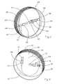
- the transmitter 54 comprises a drum 56 made of a material which is a good heat conductor, on which the fiber of the fiber amplifier 20 is wound up.
- the drum has a bottom 58 Mistake.
- the laser light is, as already described in FIG. 1, by means of the lens 14 bundled and directed by the Faraday isolator 22.
- a lens 18 is used for Focus on the coupling point on the fiber amplifier.
- Fig.1 is at the arrangement shown here but no dichroic mirror for coupling the Pump lights are provided in the fiber laser.
- the pump light is switched on by means of a Optical fiber 60 is coupled into the first end 62 of the fiber amplifier.
- a Coupling element 64 used.
- the optical fiber 60 is through the bottom 58 of the Passed drum 56.
- two pump light sources 66 and 68 are attached.
- the radiation from the diode laser 70 is transmitted through the light guide 60 and the like
- Coupling element 64 is coupled into the fiber amplifier at the end 62.
- the radiation of the Diode laser 72 is via the coupling element 78 at the other end 80 of the fiber laser coupled.
- the output radiation of the fiber laser 20 is also in an optical fiber 82 passed.
- the optical fiber 82 leads into the tip of the missile (not shown) and emits pulsed laser radiation as the transmitter of the LADAR system.
- a cover (not shown) is provided to protect the components.
- the Lids close the front and back of the drum, thus preventing it Damage and dirt and other influences of the components.
- the carrier 56 is cylindrical with circular Cross section formed.
- the carrier is optimal to the shape of the missile adapted and has the smallest space requirement.
- the fiber amplifier 20 In addition to the outer coating 88, the laser fiber used comprises a laser jacket 90, in which the pump light 94 coupled in from the diodes 70 and 72 rotates. Thereby the laser active material in the core 92 of the laser fiber is excited and the amplification caused by continuous laser light 96.
- the fiber can be in an allowed range be bent. However, this slightly affects the effectiveness of the amplifier.
Landscapes
- Engineering & Computer Science (AREA)
- Physics & Mathematics (AREA)
- Electromagnetism (AREA)
- Computer Networks & Wireless Communication (AREA)
- General Physics & Mathematics (AREA)
- Radar, Positioning & Navigation (AREA)
- Remote Sensing (AREA)
- Plasma & Fusion (AREA)
- Optics & Photonics (AREA)
- Optical Radar Systems And Details Thereof (AREA)
- Lasers (AREA)
Abstract
Description
- Fig. 1
- zeigt den prinzipiellen Aufbau eines LADAR-Senders
- Fig.2
- zeigt schematisch den Aufbau eines Mikrochip-Lasers
- Fig.3
- zeigt die Vorderseite eines LADAR-Senders mit zylindrischem Träger
- Fig.4
- zeigt die Rückseite des LADAR-Senders aus Fig.3
- Fig.5
- zeigt den prinzipiellen Aufbau einer Laserfaser
Claims (16)
- LADAR-System, enthaltend einen Master-Oszillator mit einem Laser-aktiven Medium (44) und eine als Faserverstärker (20) ausgebildete Verstärkerstufe zur Leistungsverstärkung, mit welcher die Leistung der den Oszillator verlassenden Strahlung (52) verstärkt wird, dadurch gekennzeichnet, daß ein Trägerkörper (56) vorgesehen ist, auf welchem der Faserverstärker (20) aufgewickelt ist und der Trägerkörper (56) aus einem Material mit hoher Temperaturleitfähigkeit besteht.
- LADAR-System nach Anspruch 1, dadurch gekennzeichnet, daß der Laser (12) als Mikrochip-Laser ausgebildet ist.
- LADAR-System nach Anspruch 1 oder 2, gekennzeichnet durch einen oder mehrere Diodenlaser (24) als Pumplichtquelle für den Faserverstärker (20).
- LADAR-System nach einem der vorgehenden Ansprüche, dadurch gekennzeichnet daß es inkohärent arbeitet.
- LADAR-System nach einem der vorgehenden Ansprüche, dadurch gekennzeichnet, daß in dem Trägerkörper (56) eine Vertiefung vorgesehen ist, in welcher der Laser (12) angeordnet ist.
- LADAR-System nach einem der vorgehenden Ansprüche, dadurch gekennzeichnet, daß in dem Trägerkörper (56) eine Vertiefung vorgesehen ist, in welchem die Pumplichtquelle (24) und/oder weitere optische Teile (14, 18, 22, 26) der Laseranordnung angeordnet sind.
- LADAR-System nach einem der vorgehenden Ansprüche, dadurch gekennzeichnet, daß die Vertiefung mit einer Abdeckung verschließbar ist.
- LADAR-System nach einem der vorgehenden Ansprüche, dadurch gekennzeichnet, daß der Trägerkörper (56) zylindrisch oder prismatisch mit eliptischem oder nierenförmigem Querschnitt ist, wobei an den Stirnflächen jeweils eine Vertiefung für die Bauteile vorgesehen ist und die Verstärkerfaser (20) um den Mantel gewickelt ist.
- LADAR-System nach einem der vorgehenden Ansprüche, gekennzeichnet durch einen optischen Faraday-Isolator (22) zwischen dem Master-Oszillator und dem Faserverstärker (20).
- LADAR-System nach einem der vorgehenden Ansprüche, gekennzeichnet durch einen dichroitischen Strahlteiler (28) vor dem Faserverstärker (20) zur Einkopplung des Pumplichts.
- LADAR-System nach einem der Ansprüche 1 bis 9, gekennzeichnet durch eine Faseroptik (60) zur Einkopplung des Pumplichts.
- LADAR-System nach einem der vorgehenden Ansprüche, dadurch gekennzeichnet, daß das Pumplicht an beiden Enden (62, 80) des Faserverstärkers (20) einkoppelbar ist.
- LADAR-System nach Anspruch 12, dadurch gekennzeichnet daß der Faserverstärker (20) als Doppelkernfaser ausgebildet ist und die Fasern der Pumplaser (70, 72) direkt mit dem Pumpkern verbunden sind.
- LADAR-System nach einem der vorgehenden Ansprüche, gekennzeichnet durch Wärmeleitpaste, in welche die Verstärkerfaser (20) eingebettet ist.
- LADAR-System nach einem der vorgehenden Ansprüche, dadurch gekennzeichnet, daß die Verstärkerfaser (20) mittels wärmeleitendem Klebstoff an einem Träger (56) befestigt ist.
- LADAR-System nach einem der vorgehenden Ansprüche, gekennzeichnet durch eine Lichtleitfaser (82) zum Transport der Laserstrahlung zur Sendeoptik.
Applications Claiming Priority (2)
| Application Number | Priority Date | Filing Date | Title |
|---|---|---|---|
| DE10200362 | 2002-01-08 | ||
| DE10200362A DE10200362A1 (de) | 2002-01-08 | 2002-01-08 | Laseranordnung für Zielsuchköpfe |
Publications (3)
| Publication Number | Publication Date |
|---|---|
| EP1335457A2 true EP1335457A2 (de) | 2003-08-13 |
| EP1335457A3 EP1335457A3 (de) | 2004-12-29 |
| EP1335457B1 EP1335457B1 (de) | 2006-07-12 |
Family
ID=7711633
Family Applications (1)
| Application Number | Title | Priority Date | Filing Date |
|---|---|---|---|
| EP02028330A Expired - Lifetime EP1335457B1 (de) | 2002-01-08 | 2002-12-17 | Ladar-System für Flugkörper |
Country Status (3)
| Country | Link |
|---|---|
| US (1) | US6724470B2 (de) |
| EP (1) | EP1335457B1 (de) |
| DE (2) | DE10200362A1 (de) |
Cited By (2)
| Publication number | Priority date | Publication date | Assignee | Title |
|---|---|---|---|---|
| EP1589353A1 (de) | 2004-04-20 | 2005-10-26 | Diehl BGT Defence GmbH & Co.KG | Modul für ein Lasermessgerät mit Glasfasern und bidirektionaler optischer Verstärkung |
| EP3029488A1 (de) * | 2014-12-04 | 2016-06-08 | Hexagon Technology Center GmbH | Distanzmessgerät mit einer Laser-artigen Lichtquelle |
Families Citing this family (19)
| Publication number | Priority date | Publication date | Assignee | Title |
|---|---|---|---|---|
| JP2005091286A (ja) * | 2003-09-19 | 2005-04-07 | Nec Corp | レーザ測距装置 |
| JP2007530964A (ja) * | 2004-04-02 | 2007-11-01 | ライカ ジオシステムズ アクチェンゲゼルシャフト | スペクトルおよび空間選択性を特徴とする電子距離測定装置 |
| DE102004031097B4 (de) * | 2004-06-28 | 2012-02-09 | Diehl Bgt Defence Gmbh & Co. Kg | Lasermessgerät |
| US7649616B2 (en) * | 2004-07-08 | 2010-01-19 | Lockheed Martin Corporation | Fiber laser ladar |
| DE102004051147A1 (de) * | 2004-10-15 | 2006-04-20 | Callidus Precision Systems Gmbh | Verfahren und Einrichtung für einen passiven optischen Impulsvervielfacher zur Erzeugung einer Impulsfolge für ein scannendes Laserentfernungsmessgerät |
| US7671337B1 (en) | 2005-11-29 | 2010-03-02 | Lockheed Martin Corporation | System and method for pointing a laser beam |
| US7760976B1 (en) | 2006-11-29 | 2010-07-20 | Lockheed Martin Corporation | Method and system for pointing a laser beam |
| US7429734B1 (en) * | 2006-11-29 | 2008-09-30 | Aculight Corporation | System and method for aircraft infrared countermeasures to missiles |
| US7947937B1 (en) * | 2007-10-19 | 2011-05-24 | Langner F Richard | Laser guided projectile device and method therefor |
| US8089617B2 (en) * | 2009-01-21 | 2012-01-03 | Raytheon Company | Energy efficient laser detection and ranging system |
| US9478931B2 (en) * | 2013-02-04 | 2016-10-25 | Nlight Photonics Corporation | Method for actively controlling the optical output of a seed laser |
| US9263855B2 (en) | 2013-03-15 | 2016-02-16 | Nlight Photonics Corporation | Injection locking of gain switched diodes for spectral narrowing and jitter stabilization |
| US10096965B2 (en) | 2014-03-13 | 2018-10-09 | Nlight, Inc. | Algorithms for rapid gating of seed suspendable pulsed fiber laser amplifiers |
| US9806488B2 (en) | 2015-06-30 | 2017-10-31 | Nlight, Inc. | Adaptive boost control for gating picosecond pulsed fiber lasers |
| US12399279B1 (en) | 2016-02-15 | 2025-08-26 | Red Creamery Llc | Enhanced hybrid LIDAR with high-speed scanning |
| US12399278B1 (en) | 2016-02-15 | 2025-08-26 | Red Creamery Llc | Hybrid LIDAR with optically enhanced scanned laser |
| US11556000B1 (en) | 2019-08-22 | 2023-01-17 | Red Creamery Llc | Distally-actuated scanning mirror |
| US12123950B2 (en) | 2016-02-15 | 2024-10-22 | Red Creamery, LLC | Hybrid LADAR with co-planar scanning and imaging field-of-view |
| CN112383350A (zh) * | 2020-08-14 | 2021-02-19 | 长春理工大学 | 一种发射车与导弹间空间激光通信系统 |
Family Cites Families (7)
| Publication number | Priority date | Publication date | Assignee | Title |
|---|---|---|---|---|
| DE4306919C2 (de) * | 1993-03-05 | 1995-10-05 | Daimler Benz Aerospace Ag | Verfahren zur Abstimmung eines monolithischen Einfrequenz-Mirokristall-Lasers |
| JPH1084154A (ja) * | 1996-09-09 | 1998-03-31 | Fujitsu Ltd | 光増幅装置 |
| US5847816A (en) * | 1997-01-14 | 1998-12-08 | Mcdonnell Douglas Corporation | Fiber optic micro-doppler ladar system and operating method therefor |
| DE19702681C2 (de) * | 1997-01-25 | 1999-01-14 | Lzh Laserzentrum Hannover Ev | Nichtplanarer Ringlaser mit Güteschaltung im Einfrequenzbetrieb |
| US6334020B1 (en) * | 1999-09-30 | 2001-12-25 | The Boeing Company | Compact package structure for fiber optic devices |
| JP3449316B2 (ja) * | 1999-10-04 | 2003-09-22 | 日本電気株式会社 | 光ファイバ増幅装置 |
| US6496301B1 (en) * | 2000-03-10 | 2002-12-17 | The United States Of America As Represented By The Secretary Of The Navy | Helical fiber amplifier |
-
2002
- 2002-01-08 DE DE10200362A patent/DE10200362A1/de not_active Withdrawn
- 2002-12-17 EP EP02028330A patent/EP1335457B1/de not_active Expired - Lifetime
- 2002-12-17 DE DE50207489T patent/DE50207489D1/de not_active Expired - Lifetime
-
2003
- 2003-01-06 US US10/336,870 patent/US6724470B2/en not_active Expired - Fee Related
Cited By (3)
| Publication number | Priority date | Publication date | Assignee | Title |
|---|---|---|---|---|
| EP1589353A1 (de) | 2004-04-20 | 2005-10-26 | Diehl BGT Defence GmbH & Co.KG | Modul für ein Lasermessgerät mit Glasfasern und bidirektionaler optischer Verstärkung |
| EP3029488A1 (de) * | 2014-12-04 | 2016-06-08 | Hexagon Technology Center GmbH | Distanzmessgerät mit einer Laser-artigen Lichtquelle |
| US10175343B2 (en) | 2014-12-04 | 2019-01-08 | Hexagon Technology Center Gmbh | Rangefinder with a laser-like light source |
Also Published As
| Publication number | Publication date |
|---|---|
| EP1335457B1 (de) | 2006-07-12 |
| US20030202168A1 (en) | 2003-10-30 |
| DE50207489D1 (de) | 2006-08-24 |
| DE10200362A1 (de) | 2003-07-24 |
| EP1335457A3 (de) | 2004-12-29 |
| US6724470B2 (en) | 2004-04-20 |
Similar Documents
| Publication | Publication Date | Title |
|---|---|---|
| EP1335457B1 (de) | Ladar-System für Flugkörper | |
| DE69504475T2 (de) | Passiv guetegeschalteter pikosekunden-mikrolaser | |
| DE3486288T2 (de) | Optischer Faserverstärker. | |
| DE3486106T2 (de) | Faseroptischer Verstärker. | |
| DE69636711T2 (de) | Laservermessungssystem | |
| DE19642925B4 (de) | Verfahren und Vorrichtung zur Erzeugung ultrakurzer Impulse mit einstellbaren Repetitionsraten von passiv modenverkoppelten Faserlasern | |
| DE69812119T2 (de) | Wiederholt gepulster festkörperlaserresonator mit mehreren verschiedenen verstärkungsmedien | |
| EP2051343A1 (de) | Faserlaser-Anordnung hoher Strahlleistung | |
| DE69011928T2 (de) | Ramankonverter und Ramanlasersysteme mit solchen Konvertern. | |
| EP1517415A1 (de) | Geodätisches Gerät mit einer Laserquelle | |
| EP1882899A1 (de) | Elektrooptischer Entfernungsmesser | |
| WO2003061084A1 (de) | Verfahren und vorrichtung zur entfernungsmessung | |
| DE19934638B4 (de) | Modensynchronisierter Festkörperlaser mit mindestens einem konkaven Faltungsspiegel | |
| DE19504373C2 (de) | Diodengepumpter Festkörper-Ringlaserkreisel | |
| DE3114815C2 (de) | Laservorrichtung | |
| DE102008025824B4 (de) | Miniaturisierter Laseroszillator-Verstärker | |
| EP0883919B1 (de) | Verfahren und vorrichtung zum betrieb einer laserdiode | |
| DE10052461B4 (de) | Vorrichtung zum Erzeugen von Laserlicht | |
| DE102012113029A1 (de) | Kurzpulslasersystem | |
| EP1589353B1 (de) | Modul für ein Lasermessgerät mit Glasfasern und bidirektionaler optischer Verstärkung | |
| EP2514048B1 (de) | Miniaturisierte laserverstärkeranordnung mit pumpquelle | |
| DE3642445C2 (de) | Halbleiterlaser mit externem Resonator und einem Fotodetektor | |
| DE69303277T2 (de) | Laservorrichtung | |
| DE4311454C2 (de) | Raman-Laser und dessen Verwendung | |
| DE102019126494A1 (de) | Transimpedanzverstärker für lidarsystem |
Legal Events
| Date | Code | Title | Description |
|---|---|---|---|
| PUAI | Public reference made under article 153(3) epc to a published international application that has entered the european phase |
Free format text: ORIGINAL CODE: 0009012 |
|
| AK | Designated contracting states |
Designated state(s): AT BE BG CH CY CZ DE DK EE ES FI FR GB GR IE IT LI LU MC NL PT SE SI SK TR |
|
| AX | Request for extension of the european patent |
Extension state: AL LT LV MK RO |
|
| PUAL | Search report despatched |
Free format text: ORIGINAL CODE: 0009013 |
|
| AK | Designated contracting states |
Kind code of ref document: A3 Designated state(s): AT BE BG CH CY CZ DE DK EE ES FI FR GB GR IE IT LI LU MC NL PT SE SI SK TR |
|
| AX | Request for extension of the european patent |
Extension state: AL LT LV MK RO |
|
| RIC1 | Information provided on ipc code assigned before grant |
Ipc: 7H 01S 3/067 A Ipc: 7H 01S 3/06 B Ipc: 7H 01S 3/0941 B Ipc: 7G 01S 7/48 B Ipc: 7G 01S 17/88 B |
|
| 17P | Request for examination filed |
Effective date: 20041127 |
|
| RAP1 | Party data changed (applicant data changed or rights of an application transferred) |
Owner name: DIEHL BGT DEFENCE GMBH & CO.KG |
|
| 17Q | First examination report despatched |
Effective date: 20050215 |
|
| AKX | Designation fees paid |
Designated state(s): DE FR GB IT SE |
|
| GRAP | Despatch of communication of intention to grant a patent |
Free format text: ORIGINAL CODE: EPIDOSNIGR1 |
|
| RIC1 | Information provided on ipc code assigned before grant |
Ipc: G01S 17/88 20060101ALI20060210BHEP Ipc: H01S 3/067 20060101AFI20060210BHEP Ipc: H01S 3/0941 20060101ALI20060210BHEP Ipc: G01S 7/48 20060101ALI20060210BHEP |
|
| GRAS | Grant fee paid |
Free format text: ORIGINAL CODE: EPIDOSNIGR3 |
|
| GRAA | (expected) grant |
Free format text: ORIGINAL CODE: 0009210 |
|
| AK | Designated contracting states |
Kind code of ref document: B1 Designated state(s): DE FR GB IT SE |
|
| PG25 | Lapsed in a contracting state [announced via postgrant information from national office to epo] |
Ref country code: IT Free format text: LAPSE BECAUSE OF FAILURE TO SUBMIT A TRANSLATION OF THE DESCRIPTION OR TO PAY THE FEE WITHIN THE PRESCRIBED TIME-LIMIT;WARNING: LAPSES OF ITALIAN PATENTS WITH EFFECTIVE DATE BEFORE 2007 MAY HAVE OCCURRED AT ANY TIME BEFORE 2007. THE CORRECT EFFECTIVE DATE MAY BE DIFFERENT FROM THE ONE RECORDED. Effective date: 20060712 |
|
| REG | Reference to a national code |
Ref country code: GB Ref legal event code: FG4D Free format text: NOT ENGLISH |
|
| REF | Corresponds to: |
Ref document number: 50207489 Country of ref document: DE Date of ref document: 20060824 Kind code of ref document: P |
|
| REG | Reference to a national code |
Ref country code: SE Ref legal event code: TRGR |
|
| GBT | Gb: translation of ep patent filed (gb section 77(6)(a)/1977) |
Effective date: 20061018 |
|
| ET | Fr: translation filed | ||
| PLBE | No opposition filed within time limit |
Free format text: ORIGINAL CODE: 0009261 |
|
| STAA | Information on the status of an ep patent application or granted ep patent |
Free format text: STATUS: NO OPPOSITION FILED WITHIN TIME LIMIT |
|
| 26N | No opposition filed |
Effective date: 20070413 |
|
| PGFP | Annual fee paid to national office [announced via postgrant information from national office to epo] |
Ref country code: SE Payment date: 20111223 Year of fee payment: 10 |
|
| PGFP | Annual fee paid to national office [announced via postgrant information from national office to epo] |
Ref country code: GB Payment date: 20121220 Year of fee payment: 11 |
|
| PGFP | Annual fee paid to national office [announced via postgrant information from national office to epo] |
Ref country code: FR Payment date: 20130130 Year of fee payment: 11 Ref country code: DE Payment date: 20130220 Year of fee payment: 11 |
|
| PG25 | Lapsed in a contracting state [announced via postgrant information from national office to epo] |
Ref country code: SE Free format text: LAPSE BECAUSE OF NON-PAYMENT OF DUE FEES Effective date: 20121218 |
|
| REG | Reference to a national code |
Ref country code: DE Ref legal event code: R119 Ref document number: 50207489 Country of ref document: DE |
|
| GBPC | Gb: european patent ceased through non-payment of renewal fee |
Effective date: 20131217 |
|
| REG | Reference to a national code |
Ref country code: DE Ref legal event code: R119 Ref document number: 50207489 Country of ref document: DE Effective date: 20140701 |
|
| REG | Reference to a national code |
Ref country code: FR Ref legal event code: ST Effective date: 20140829 |
|
| PG25 | Lapsed in a contracting state [announced via postgrant information from national office to epo] |
Ref country code: DE Free format text: LAPSE BECAUSE OF NON-PAYMENT OF DUE FEES Effective date: 20140701 |
|
| PG25 | Lapsed in a contracting state [announced via postgrant information from national office to epo] |
Ref country code: FR Free format text: LAPSE BECAUSE OF NON-PAYMENT OF DUE FEES Effective date: 20131231 Ref country code: GB Free format text: LAPSE BECAUSE OF NON-PAYMENT OF DUE FEES Effective date: 20131217 |