EP1335448A1 - Antenna device and portable terminal - Google Patents
Antenna device and portable terminal Download PDFInfo
- Publication number
- EP1335448A1 EP1335448A1 EP20000970214 EP00970214A EP1335448A1 EP 1335448 A1 EP1335448 A1 EP 1335448A1 EP 20000970214 EP20000970214 EP 20000970214 EP 00970214 A EP00970214 A EP 00970214A EP 1335448 A1 EP1335448 A1 EP 1335448A1
- Authority
- EP
- European Patent Office
- Prior art keywords
- antenna
- mobile phone
- antenna device
- substrate
- plate
- Prior art date
- Legal status (The legal status is an assumption and is not a legal conclusion. Google has not performed a legal analysis and makes no representation as to the accuracy of the status listed.)
- Withdrawn
Links
Images





Classifications
-
- H—ELECTRICITY
- H01—ELECTRIC ELEMENTS
- H01Q—ANTENNAS, i.e. RADIO AERIALS
- H01Q1/00—Details of, or arrangements associated with, antennas
- H01Q1/36—Structural form of radiating elements, e.g. cone, spiral, umbrella; Particular materials used therewith
- H01Q1/38—Structural form of radiating elements, e.g. cone, spiral, umbrella; Particular materials used therewith formed by a conductive layer on an insulating support
-
- H—ELECTRICITY
- H01—ELECTRIC ELEMENTS
- H01Q—ANTENNAS, i.e. RADIO AERIALS
- H01Q1/00—Details of, or arrangements associated with, antennas
- H01Q1/12—Supports; Mounting means
- H01Q1/22—Supports; Mounting means by structural association with other equipment or articles
- H01Q1/24—Supports; Mounting means by structural association with other equipment or articles with receiving set
- H01Q1/241—Supports; Mounting means by structural association with other equipment or articles with receiving set used in mobile communications, e.g. GSM
- H01Q1/242—Supports; Mounting means by structural association with other equipment or articles with receiving set used in mobile communications, e.g. GSM specially adapted for hand-held use
- H01Q1/243—Supports; Mounting means by structural association with other equipment or articles with receiving set used in mobile communications, e.g. GSM specially adapted for hand-held use with built-in antennas
-
- H—ELECTRICITY
- H01—ELECTRIC ELEMENTS
- H01Q—ANTENNAS, i.e. RADIO AERIALS
- H01Q1/00—Details of, or arrangements associated with, antennas
- H01Q1/36—Structural form of radiating elements, e.g. cone, spiral, umbrella; Particular materials used therewith
-
- H—ELECTRICITY
- H01—ELECTRIC ELEMENTS
- H01Q—ANTENNAS, i.e. RADIO AERIALS
- H01Q1/00—Details of, or arrangements associated with, antennas
- H01Q1/36—Structural form of radiating elements, e.g. cone, spiral, umbrella; Particular materials used therewith
- H01Q1/362—Structural form of radiating elements, e.g. cone, spiral, umbrella; Particular materials used therewith for broadside radiating helical antennas
-
- H—ELECTRICITY
- H01—ELECTRIC ELEMENTS
- H01Q—ANTENNAS, i.e. RADIO AERIALS
- H01Q9/00—Electrically-short antennas having dimensions not more than twice the operating wavelength and consisting of conductive active radiating elements
- H01Q9/04—Resonant antennas
- H01Q9/16—Resonant antennas with feed intermediate between the extremities of the antenna, e.g. centre-fed dipole
-
- H—ELECTRICITY
- H01—ELECTRIC ELEMENTS
- H01Q—ANTENNAS, i.e. RADIO AERIALS
- H01Q9/00—Electrically-short antennas having dimensions not more than twice the operating wavelength and consisting of conductive active radiating elements
- H01Q9/04—Resonant antennas
- H01Q9/16—Resonant antennas with feed intermediate between the extremities of the antenna, e.g. centre-fed dipole
- H01Q9/26—Resonant antennas with feed intermediate between the extremities of the antenna, e.g. centre-fed dipole with folded element or elements, the folded parts being spaced apart a small fraction of operating wavelength
-
- H—ELECTRICITY
- H01—ELECTRIC ELEMENTS
- H01Q—ANTENNAS, i.e. RADIO AERIALS
- H01Q9/00—Electrically-short antennas having dimensions not more than twice the operating wavelength and consisting of conductive active radiating elements
- H01Q9/04—Resonant antennas
- H01Q9/16—Resonant antennas with feed intermediate between the extremities of the antenna, e.g. centre-fed dipole
- H01Q9/28—Conical, cylindrical, cage, strip, gauze, or like elements having an extended radiating surface; Elements comprising two conical surfaces having collinear axes and adjacent apices and fed by two-conductor transmission lines
- H01Q9/285—Planar dipole
Definitions
- the present invention relates to an antenna device and a mobile terminal and more particularly to an antenna device contained in a mobile phone and a mobile phone using the antenna device.
- Antennas contained in housings of mobile phones are conventionally known as receiving/transmitting antennas for the mobile phones.
- These antennas are classified into linear antennas and plate antennas depending on their characteristics.
- Fig. 20 is a schematic plan view of a mobile phone containing a dipole antenna that is one of conventional linear antennas.
- a conventional mobile phone 1x has a housing 10 and an antenna device 3x accommodated in housing 10.
- Antenna device 3x has a substrate 11 and a dipole antenna 121 provided on substrate 11.
- Dipole antenna 121 has two meander-like antenna portions 121a and 121b respectively connected to a feed point 12.
- the electrical length of dipole antenna 121 is ⁇ /2.
- dipole antenna 121 is known as an antenna which allows for reduction of polarization loss for a wave polarized vertically to the ground (a vertically polarized wave) at the time of a call.
- Fig. 21 is a diagram showing a radiation pattern of the conventional dipole antenna shown in Fig. 20.
- Fig. 21 when mobile phone 1x is placed upright, particularly when the electrical length of the antenna is ⁇ /2 ⁇ A (A is an integer), a null point 134 of the radiation pattern as indicated by solid lines 131 and 132 is in a horizontal plane. This disadvantageously reduces the gain.
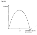
- Fig. 22 is a graph showing the relation between the electrical length of the antenna and the current distribution on the antenna element in the conventional dipole antenna. As shown in Fig. 22, in the dipole antenna having an electrical length of ⁇ /2, the maximum value of the current distribution exists at the portion where the electrical length of the antenna is ⁇ /4, that is, at the central portion of the antenna. As a hand easily touches this portion, an antenna gain degrades particularly when a hand touches it.
- Fig. 23 is a plan view of a mobile phone having a conventional plate antenna.
- a mobile phone 1y has a housing 10 and an antenna device 3y accommodated in housing 10.
- Antenna device 3y has a substrate 11 and a plate antenna 122 provided on substrate 11. Plate antenna 122 is connected to a feed point 12.
- Such a plate antenna 122 easily receives and transmits both a vertically polarized wave and a horizontally polarized wave with respect to the ground.
- degradation amount of gains when a finger touches the antenna is small as compared with a linear antenna, since the current in the vicinity of the feed point is dispersed.
- Plate antenna 122 for example a patch antenna, requires about ⁇ as the total perimeter of the antenna, the size of the antenna inevitably increases and thus mobile phone 1y itself increases in size.
- An object of the present invention is to provide an antenna device capable of receiving and transmitting both a vertically polarized wave and a horizontally polarized wave, being reduced in size and having small gain degradation during a call.
- An antenna device in accordance with the present invention includes a substrate and an antenna provided on the substrate and having an electrical length of approximately ( ⁇ /2) ⁇ A (A is an integer).
- the antenna includes a plate antenna portion positioned at a portion where an electrical length from an end portion is approximately ⁇ /4+( ⁇ /2) ⁇ B (B is an integer), and a linear antenna portion connected to the plate antenna.
- the linear antenna portion can mainly receive and transmit either one of a vertically polarized wave or a horizontally polarized wave
- the plate antenna portion can receive and transmit both the vertically polarized wave and the horizontally polarized wave.
- the electrical length of the antenna is approximately ( ⁇ /2) ⁇ A (A is an integer)
- the current is large at the portion where the electrical length from the end portion of the antenna is approximately ⁇ /4+( ⁇ /2) ⁇ B (B is an integer).
- this portion is provided with the plate antenna portion and therefore the current can be distributed. Accordingly, even when a finger is placed on this portion, degradation in gain can be reduced.
- the antenna since the antenna includes the linear antenna portion, the antenna can be reduced in size as compared with an antenna configured only with a plate antenna portion.
- the present invention can provide an antenna having a high gain even at the time of a call, assuring a gain when the terminal is placed upright, and having a small size.
- the linear antenna portion includes at least one selected from the group consisting of a monopole antenna, a zigzag antenna, a meander line antenna and a helical antenna.
- the substrate has a main surface having conductivity.
- the antenna further includes a connection portion connected to the main surface of the substrate. In this case, since the antenna is connected to the main surface having conductivity, an image is formed on the substrate. As a result, the electrical length of the antenna is approximately double the physical length of the antenna, so that the physical length of the antenna can be shortened. Therefore, the antenna device can be reduced in size.
- the substrate has a main surface and a side surface continuous with the main surface, and the antenna is provided on the side surface.
- the main surface is not provided with an antenna, other device and the like can be placed on the main surface.
- a mobile terminal in accordance with the present invention includes a housing and an antenna device contained in the housing.
- the antenna device includes a substrate and an antenna provided on the substrate and having an electrical length of approximately ( ⁇ /2) ⁇ A (A is an integer).
- the antenna includes a plate antenna portion positioned at a portion where an electrical length from an end portion is approximately ⁇ /4+( ⁇ /2) ⁇ B (B is an integer), and a linear antenna portion connected to the plate antenna portion.
- the linear antenna portion can mainly receive and transmit either one of a vertically polarized wave or a horizontally polarized wave and a plate antenna portion can receive and transmit both the horizontally polarized wave and the vertically polarized wave.
- a plate antenna portion can receive and transmit both the horizontally polarized wave and the vertically polarized wave.
- the electrical length of the antenna is approximately ( ⁇ /2) ⁇ A (A is an integer)
- the current is large at the portion where the electrical length from the end portion of the antenna is approximately ⁇ /4+( ⁇ /2) ⁇ B (B is an integer).
- this portion is provided with the plate antenna portion, the current can be dispersed. Therefore, even when a finger or the like is placed on this portion, degradation in gain can be reduced.
- the antenna includes the linear antenna portion, and thus the antenna and the mobile terminal can be reduced in size as compared with an antenna configured only with a plate antenna portion.
- the antenna device since the antenna device is contained in the housing, the antenna device is less affected by a human body. As a result, degradation in gain can be prevented.
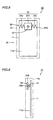
- Fig. 1 is a schematic plan view of a mobile phone having an antenna device in accordance with a first embodiment of the present invention.
- Fig. 2 is a side view of the mobile phone seen from a direction indicated by an arrow II in Fig. 1.
- mobile phone 1a has a housing 10 and an antenna device 3a contained in housing 10.
- Antenna device 3a includes a substrate 11 and an antenna 21 provided on substrate 11 and having an electrical length of ( ⁇ /2) ⁇ A (A is an integer).
- Antenna 21 has a plate antenna 21b as a plate antenna portion positioned at a portion where an electrical length from an end portion 21d is approximately ⁇ /4+( ⁇ /2) ⁇ B (B is an integer), and meander line antennas 21a and 21c as a linear antenna portion connected to plate antenna 21b.
- Substrate 11 is formed by depositing a high conductive metal such as copper on a prescribed insulating substrate. It is noted that the metal formed on the insulating substrate can be replaced by one having the same level of conductivity as copper. Substrate 11 extends in a longitudinal direction and has a rectangular shape. Antenna 21 is provided to extend along the short side of substrate 11.
- Antenna 21 has plate antenna 21b as a plate antenna portion positioned at the central portion and meander line antennas 21a and 21c as a linear antenna portion positioned at opposing ends thereof. Plate antenna 21b is connected to feed point 12. Both meander line antennas 21a and 21c and plate antenna 21b are provided on a main surface 11a of substrate 11 as opposed to main surface 11a. Plate antenna 21b is connected to a radio unit, not shown, through feed point 12. When a person is making a call with mobile phone 1a on the ear, the direction in which antenna 21 extends is approximately at 30° (a zenith angle 30°) with respect to a vertical direction. Antenna 21 is contained in housing 10.
- Fig. 3 is a graph showing the relation between the electrical length of the antenna and the current in mobile phone 1a shown in Figs. 1 and 2.
- regions 221a and 221c correspond to regions where meander line antennas 21a and 21c exist
- region 221b corresponds to a region where plate antenna 21b exists.
- provision of plate antenna 21b in region 221b where the current becomes larger can prevent the current value increase in this portion.
- meander line antennas 21a and 21c receive and transmit either a vertically or horizontally polarized wave and plate antenna 21b receives and transmits both the vertically and horizontally polarized waves.
- both the vertically and horizontally polarized waves can be received and transmitted, thereby preventing degradation in gain.
- antenna 21 is contained in housing 10, so that antenna 21 is not in direct contact with a human body. As a result, antenna 21 is less affected by a human body and therefore degradation in gain due to a human body can be prevented.
- Fig. 4 is a schematic plan view of the mobile phone having the antenna device in accordance with a second embodiment of the present invention.
- Fig. 5 is a side view of the mobile phone seen from a direction indicated by an arrow V in Fig. 4.
- a mobile phone 1b and an antenna device 3b in accordance with the second embodiment of the present invention differs from antenna device 3a illustrated in the first embodiment in that antenna 21 is provided on a zenith plane 11b as a side surface of substrate 11. Antenna 21 is connected to feed point 12.
- antenna device 3b and mobile phone 1b thus configured has an effect similar to that of antenna device 3a and mobile phone 1b illustrated in the first embodiment.
- antenna 21 is provided on zenith plane 11b, an area available on main surface 11a is increased as compared with antenna 21 provided on main surface 11a. As a result, other components can be placed on main surface 11a.
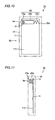
- Fig. 6 is a schematic plan view of the mobile phone having the antenna device in accordance with a third embodiment of the present invention.
- Fig. 7 is a side view of the mobile phone seen from a direction indicated by an arrow VII in Fig. 6.
- a mobile phone 1c and an antenna device 3c in accordance with the third embodiment of the present invention differs from mobile phone 1a and antenna device 3a illustrated in the first embodiment in that a linear antenna portion of an antenna 23 is configured with helical antennas 23a and 23c.
- Helical antennas 23a and 23c are configured in a helical manner and has one end connected to plate antenna 21b.
- Helical antennas 23a and 23c are provided in a spiral manner and are not in direct contact with substrate 11.
- Mobile phone 1c has housing 10 and antenna device 3c contained in housing 10.
- Antenna device 3c includes substrate 11 and antenna 23 provided on substrate 11 and having an electrical length of ( ⁇ /2) ⁇ A (A is an integer).
- Antenna 23 has plate antenna 21b as a plate antenna portion positioned at a portion where an electrical length from an end portion 23d is approximately ⁇ /4+( ⁇ /2) ⁇ B (B is an integer), and helical antennas 23a and 23c as a linear antenna portion connected to plate antenna 21b.
- Antenna device 3c and mobile phone 1c thus configured has an effect similar to that of antenna device 3a and mobile phone 1c illustrated in the first embodiment.
- Fig. 8 is a schematic plan view of the mobile phone having the antenna device in accordance with a fourth embodiment of the present invention.
- Fig. 9 is a side view of the mobile phone seen from a direction indicated by an arrow IX in Fig. 8.
- an antenna device 3d in accordance with the fourth embodiment of the present invention differs from antenna 21 illustrated in the first embodiment in that an antenna 24 is configured with zigzag antennas 24a and 24c and plate antenna 21b.
- mobile phone 1d has housing 10 and antenna device 3d contained in housing 10.
- Antenna device 3d includes substrate 11 and antenna 24 provided on substrate 11 and having an electrical length of ( ⁇ /2) ⁇ A (A is an integer).
- Antenna 24 has plate antenna 21b as a plate antenna portion positioned at a portion where an electrical length from an end portion 24d is approximately ⁇ /4+( ⁇ /2) ⁇ B (B is an integer), and zigzag antennas 24a and 24c as a linear antenna portion connected to plate antenna 21b.
- Antenna device 3d and mobile phone 1d thus configured also has an effect similar to that of antenna device 3a and mobile phone 1a illustrated in the first embodiment.
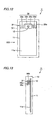
- Fig. 10 is a plan view of the mobile phone having the antenna device in accordance with a fifth embodiment of the present invention.
- Fig. 11 is a side view of the mobile phone seen from a direction indicated by an arrow XI in Fig. 10.
- a mobile phone 1e has housing 10 and an antenna device 3e contained in housing 10.
- Antenna device 3e includes substrate 11 and an antenna 25 provided on substrate 11 and having an electrical length of ( ⁇ /2) ⁇ A (A is an integer).
- Antenna 25 has a connection portion 25a as a plate antenna portion positioned at a portion where an electrical length from an end portion 25d is approximately ⁇ /4+( ⁇ /2) ⁇ B (B is an integer), a plate antenna 25b and a zigzag antenna 25c as a linear antenna portion connected to connection portion 25a through plate antenna 25b.
- Antenna 25 is provided on main surface 11a of substrate 11.
- Antenna 25 has connection portion 25a connected to main surface 11a, plate antenna 25b connected to connection portion 25a, and zigzag antenna 25c connected to plate antenna 25b.
- Connection portion 25a is formed of a plate antenna and connects main surface 11a having conductivity to plate antenna 25b.
- Connection portion 25a is also connected to feed point 12.
- Plate antenna 25b is provided as opposed to main surface 11a and has one end connected to connection portion 25a and the other end connected to zigzag antenna 25c. Since connection portion 25a is connected to main surface 11a having conductivity, an image of the antenna is formed also on main surface 11a. Therefore, although the physical length of antenna 25 is ( ⁇ /4) ⁇ A (A is an integer), the electrical length is ( ⁇ /2) ⁇ A (A is an integer).
- antenna device 3e and mobile phone 1e thus configured has an effect similar to that of antenna device 3a and mobile phone 1a illustrated in the first embodiment.
- antenna device 3e and mobile phone 1e can be reduced in size, since the physical length of antenna 25 is reduced.
- plate antenna 25b is connected with zigzag antenna 25c in this embodiment, plate antenna 25b may be connected with a monopole antenna, a meander line antenna and a helical antenna.
- Fig. 12 is a plan view of the mobile phone having the antenna device in accordance with a sixth embodiment of the present invention.
- Fig. 13 is a side view of the mobile phone seen from a direction indicated by an arrow XIII in Fig. 12.
- a mobile phone 1f has housing 10 and an antenna device 3f contained in housing 10.
- Antenna device 3f includes substrate 11 and an antenna 26 provided on substrate 11 and having an electrical length of ( ⁇ /2) ⁇ A (A is an integer).
- Antenna 26 has a plate antenna 26c as a plate portion positioned at a portion where an electrical length from an end portion 26e is approximately ⁇ /4+( ⁇ /2) ⁇ B (B is an integer), meander line antennas 26a and 26d as a linear antenna portion connected to plate antenna 26c, and a connection portion 26b.
- Plate antenna 26c is connected to feed point 12 and also to connection portion 26b. Connection portion 26b connects plate antenna 26c to main surface 11a having conductivity. Both meander line antennas 26a and 26d and plate antenna 26c are provided as opposed to main surface 11a. Antenna 26 is connected to main surface 11a at connection portion 26b. Therefore, an image of antenna 26 is formed on main surface 11a. Although the physical length of antenna 26 is ( ⁇ /4) ⁇ A (A is an integer), the electrical length is ( ⁇ /2) ⁇ A (A is an integer). Plate antenna 26c is provided at the central portion of antenna 26, specifically at a portion where the current value is maximized in antenna 26.
- Antenna device 3f and mobile phone 1f thus configured also has an effect similar to that of antenna device 3e and mobile phone 1e illustrated in the fifth embodiment.
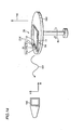
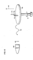
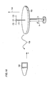
- Figs. 14 to 16 show the steps of measuring radiation patterns in Y-Z plane.
- mobile phone 1a (Fig. 1) illustrated in the first embodiment was first prepared.
- the electrical length of antenna 21 was ⁇ /2.
- Plate antenna 21b was arranged at a position where the electrical length is ⁇ /4 from the end portion 21d of the antenna.
- mobile phone 1a was placed on a table 150 such that a Y direction (a direction in which the shorter side of substrate 11 extends) and a Z direction (a direction in which the longer side of substrate 11 extends), as shown in Fig. 1, were on a horizontal plane.
- X direction was in a vertical direction indicated by an arrow 140.
- Table 150 was rotatable in a direction indicated by arrow R.
- a radio wave at a frequency of 1.95 GHz was radiated at a prescribed power from the radio transceiver unit on substrate 11 through antenna device 3a.
- table 150 was rotated in the direction indicated by arrow R.
- antenna device 3a radiated a radio wave as indicated by an arrow 151.
- the field intensity of this radio wave was measured by an measuring antenna 160 and the field intensity was found for a vertically polarized wave in a direction indicated by an arrow V and a horizontally polarized wave in a direction indicated by an arrow H for this radio wave.
- a dipole antenna 170 was placed on table 150.
- Dipole antenna 170 is provided with a feed point 171 at the central portion, and feed point 171 is connected to a coaxial cable 172.
- Coaxial cable 172 is connected to a prescribed radio transceiver unit.
- Dipole antenna 170 extends approximately parallel to the vertical direction indicated by an arrow 140.
- table 150 being rotated in a direction indicated by arrow R, similar power as provided by the radio transceiver unit to antenna 3a shown in Fig. 14 was provided to dipole antenna 170 so that a radio wave at a frequency of 1.95 GHz as indicated by an arrow 152 was radiated from dipole antenna 170. Accordingly, the radio wave indicated by arrow 152 was radiated from dipole antenna 170.
- This radio wave is a vertically polarized wave in a direction shown by arrow V. The field intensity of this radio wave was measured by measuring antenna 160.
- dipole antenna 170 Similar power as provided by the radio transceiver unit to antenna device 3a was provided to dipole antenna 170 so that a radio wave at a frequency of 1.95 GHz as indicated by arrow 153 was radiated from dipole antenna 170.
- This radio wave is a horizontally polarized wave in a direction indicated by an arrow H.
- the field intensity of this radio wave was obtained by measuring antenna 160.
- the radiation pattern of the antenna device in accordance with the present invention was obtained based on data obtained form the steps shown in Figs. 14 - 16. The result is shown in Fig. 17.
- a solid line 301 shows the gain of the vertically polarized wave component of the radio wave radiated from antenna device 3a shown in Fig. 14, with respect to the field intensity of the vertically polarized wave radiated from dipole antenna 170 in the step shown in Fig. 15.
- a dotted line 302 shows the gain of the horizontally polarized wave component of the radio wave radiated from antenna device 3a shown in Fig. 14, with respect to the field intensity of the horizontally polarized wave radiated from dipole antenna 170 in the step shown in Fig. 16.
- the gain of the vertically polarized wave is relatively uniform in all directions.
- the gain of the horizontally polarized wave is also generally uniform in all directions. Therefore, it is appreciated that various polarized waves can be received and transmitted.
- mobile phone 1x having the conventional antenna device 3x shown in Fig. 20 was used and placed on table 150 with Y-axis and X-axis oriented in the horizontal direction and with X-axis parallel to the vertical direction in accordance with the step shown in Fig. 14.
- table 150 being rotated in the direction indicated by arrow R, a radio wave at a frequency of 1.95 GHz was radiated through antenna device 3x.
- similar power as provided by the radio transceiver unit to antenna device 3a was provided to antenna device 3x.
- the vertically polarized wave component and the horizontally polarized wave component of this radiated radio wave were measured by measuring antenna 160.
- the radiation pattern for such a conventional antenna is shown in Fig. 18. In Fig.
- a solid line 311 shows the gain of the field intensity of the vertically polarized wave component of the radio wave radiated from antenna device 3x in accordance with the step shown in Fig. 14, with respect to the field intensity of the vertically polarized wave measured in the step shown in Fig. 15.
- a dotted line 312 shows the gain of the field intensity of the horizontally polarized wave component of the radio wave radiated from antenna device 3x in accordance with the step shown in Fig.
- the gain of the vertically polarized wave is extremely small in the Y-axis direction in the conventional one.
- mobile phone 1y having the conventional antenna device 3y shown in Fig. 23 was used and placed on table 150 with Y-axis and Z-axis oriented in the horizontal direction and with X-axis in parallel to the vertical direction in accordance with the similar step as shown in Fig. 14.
- table 150 being rotated in the direction indicated by arrow R, a radio wave at a frequency of 1.95 GHz was radiated through antenna device 3y.
- similar power as provided by the radio transceiver unit to antenna device 3a was provided to antenna device 3y.
- the vertically polarized wave component and the horizontally polarized wave component of this radiated radio wave were measured by measuring antenna 160.
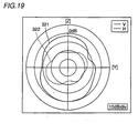
- the radiation pattern for such a conventional antenna is shown in Fig. 19.
- a solid line 321 shows the gain of the field intensity of the vertically polarized wave component of the radio wave radiated from antenna device 3y in accordance with the step shown in Fig. 14, with respect to the field intensity of the vertically polarized wave measured in the step shown in Fig. 15.
- a dotted line 322 shows the gain of the field intensity of the horizontally polarized wave component of the radio wave radiated from antenna device 3y in accordance with the step shown in Fig. 14, with respect to the field intensity of the horizontally polarized wave measured in the step shown in Fig. 16.
- gain 20 ⁇ log 10 (the field intensity of the horizontally polarized wave from antenna device 3y/the field intensity of the horizontally polarized wave from dipole antenna 170)
- This plate antenna 122 has a problem in that the total perimeter of the antenna is ⁇ and the mobile phone is increased in size.
- the maximum field intensity was obtained in the vicinity of the antenna for each of mobile phones 1a, 1x and 1y. Given that the maximum field intensity in mobile phone 1a was 100 %, the field intensity in mobile phone 1x was 130 % and the maximum field intensity in mobile phone 1y was 68 %. Therefore, even when a person touches the vicinity of the antenna, the electric field is less affected by the action of the person, because concentration of the electric field is relieved in the present invention as compared with mobile phone 1x. As a result, decrease in gain can be prevented.
- a monopole antenna can be used as a linear antenna in all the embodiments described above.
- the electrical length of antennas 21, 23, 24 is ⁇ /2 in the first to fourth embodiments.
- the antenna device and the mobile phone in accordance with the present invention can be utilized in the field of mobile phones containing antennas.
Landscapes
- Engineering & Computer Science (AREA)
- Computer Networks & Wireless Communication (AREA)
- Support Of Aerials (AREA)
- Telephone Set Structure (AREA)
Abstract
Description
(gain) = 20×log10 (the field intensity of the vertically polarized wave from
(gain) = 20×log10 (the field intensity of the horizontally polarized wave from
(gain) = 20×log10 (the field intensity of the vertically polarized wave from
(gain) = 20×log10 (the field intensity of the horizontally polarized wave from
(gain) = 20×log10 (the field intensity of the vertically polarized wave from
(gain) = 20×log10 (the field intensity of the horizontally polarized wave from
| sample | gains during call | |
| held at the left hand | held at the | |
| 1a | 0 | -0.03 |
| 1x | -2.63 | -0.09 |
| 1y | -3.84 | +0.72 |
Claims (5)
- An antenna device comprising:a substrate (11); andan antenna (21, 23, 24, 25, 26) provided on said substrate (11) and having an electrical length of approximately (λ/2)×A (A is an integer), whereinsaid antenna (21, 23, 24, 25, 26) includes a plate antenna portion (21b, 25b, 26c) positioned at a portion where an electrical length from an end portion (21d, 23d, 24d, 25d, 26e) is approximately λ/4+(λ/2)×B (B is an integer), anda linear antenna portion (21a, 21c, 23a, 23c, 24a, 24c, 25c, 26a, 26d) connected to said plate antenna portion (21b, 25b, 26c).
- The antenna device according to claim 1, whereinsaid linear antenna portion includes at least one selected from the group consisting of a monopole antenna, a zigzag antenna (24a, 24c, 25c), a meander line antenna (21a, 21c, 26a, 26d) and a helical antenna (23a, 23c).
- The antenna device according to claim 1, whereinsaid substrate (11) has a main surface (11a) having conductivity, andsaid antenna (25, 26) further includes a connection portion (25a, 26b) connected to said main surface (11a) of said substrate (11).
- The antenna device according to claim 1, whereinsaid substrate (11) has a main surface (11a) and a side surface (11b) continuous with the main surface (11a), and said antenna (21) is provided on said side surface (11b).
- A mobile terminal comprising:a housing (10); andan antenna device (3a, 3b, 3c, 3d, 3e, 3f) contained in said housing (10), whereinsaid antenna device (3a, 3b, 3c, 3d, 3e, 3f) includesa substrate (11), andan antenna (21, 23, 24, 25, 26) provided on said substrate (11) and having an electrical length of approximately (λ/2)×A (A is an integer), andsaid antenna (21, 23, 24, 25, 26) includesa plate antenna portion (21b, 25b, 26c) positioned at a portion where an electrical length from an end portion (21d, 23d, 24d, 25d, 26e) is approximately λ/4+(λ/2)×B (B is an integer), anda linear antenna portion (21a, 21c, 23a, 23c, 24a, 24c, 25c, 26a, 26d) connected to said plate antenna portion (21b, 25b, 26c).
Applications Claiming Priority (1)
| Application Number | Priority Date | Filing Date | Title |
|---|---|---|---|
| PCT/JP2000/007637 WO2002039542A1 (en) | 2000-10-31 | 2000-10-31 | Antenna device and portable terminal |
Publications (2)
| Publication Number | Publication Date |
|---|---|
| EP1335448A1 true EP1335448A1 (en) | 2003-08-13 |
| EP1335448A4 EP1335448A4 (en) | 2004-12-15 |
Family
ID=11736639
Family Applications (1)
| Application Number | Title | Priority Date | Filing Date |
|---|---|---|---|
| EP00970214A Withdrawn EP1335448A4 (en) | 2000-10-31 | 2000-10-31 | ANTENNA DEVICE AND PORTABLE TERMINAL |
Country Status (4)
| Country | Link |
|---|---|
| EP (1) | EP1335448A4 (en) |
| JP (1) | JPWO2002039542A1 (en) |
| CN (1) | CN1229893C (en) |
| WO (1) | WO2002039542A1 (en) |
Families Citing this family (1)
| Publication number | Priority date | Publication date | Assignee | Title |
|---|---|---|---|---|
| JP2004186931A (en) * | 2002-12-03 | 2004-07-02 | Ngk Spark Plug Co Ltd | Antenna compatible with multiple frequency bands |
Family Cites Families (8)
| Publication number | Priority date | Publication date | Assignee | Title |
|---|---|---|---|---|
| JPS5757618U (en) * | 1980-09-20 | 1982-04-05 | ||
| US5898411A (en) * | 1996-02-26 | 1999-04-27 | Pacific Antenna Technologies, Inc. | Single-element, multi-frequency, dipole antenna |
| JPH10107535A (en) * | 1996-09-27 | 1998-04-24 | Murata Mfg Co Ltd | Surface mount antenna |
| JP3580654B2 (en) * | 1996-12-04 | 2004-10-27 | 京セラ株式会社 | Common antenna and portable radio using the same |
| JPH10303637A (en) * | 1997-04-25 | 1998-11-13 | Harada Ind Co Ltd | Automotive TV antenna device |
| FR2772517B1 (en) * | 1997-12-11 | 2000-01-07 | Alsthom Cge Alcatel | MULTIFREQUENCY ANTENNA MADE ACCORDING TO MICRO-TAPE TECHNIQUE AND DEVICE INCLUDING THIS ANTENNA |
| US6288680B1 (en) * | 1998-03-18 | 2001-09-11 | Murata Manufacturing Co., Ltd. | Antenna apparatus and mobile communication apparatus using the same |
| JP3467752B2 (en) * | 1998-03-18 | 2003-11-17 | Necトーキン株式会社 | Mobile communication terminal and its antenna device |
-
2000
- 2000-10-31 WO PCT/JP2000/007637 patent/WO2002039542A1/en not_active Ceased
- 2000-10-31 CN CN00818025.3A patent/CN1229893C/en not_active Expired - Fee Related
- 2000-10-31 EP EP00970214A patent/EP1335448A4/en not_active Withdrawn
- 2000-10-31 JP JP2002541755A patent/JPWO2002039542A1/en active Pending
Also Published As
| Publication number | Publication date |
|---|---|
| CN1415126A (en) | 2003-04-30 |
| EP1335448A4 (en) | 2004-12-15 |
| JPWO2002039542A1 (en) | 2004-03-18 |
| WO2002039542A1 (en) | 2002-05-16 |
| CN1229893C (en) | 2005-11-30 |
Similar Documents
| Publication | Publication Date | Title |
|---|---|---|
| CN100346530C (en) | ANtenna variable directivity pattern | |
| US6768460B2 (en) | Diversity wireless device and wireless terminal unit | |
| US6424300B1 (en) | Notch antennas and wireless communicators incorporating same | |
| JP2870940B2 (en) | In-vehicle antenna | |
| US7050009B2 (en) | Internal antenna | |
| KR20050042076A (en) | Compact, low profile, single feed, multi-band, printed antenna | |
| US7031762B2 (en) | Mobile terminal including first and second housings and an antenna | |
| KR20060121981A (en) | Diversity Antenna Unit | |
| KR19990068163A (en) | Built-in antenna for radio communication terminals | |
| JP2003505963A (en) | Capacitively tuned broadband antenna structure | |
| JP4803881B2 (en) | Portable radio built-in antenna | |
| US6677907B2 (en) | Antenna device and portable terminal | |
| JPS61205004A (en) | Portable radio equipment | |
| JP4565305B2 (en) | Portable wireless terminal device | |
| US6768464B1 (en) | Antenna element and portable information terminal | |
| JP2004112044A (en) | Loop antenna | |
| JPH11274828A (en) | Mobile communication terminal and its antenna device | |
| JP3255803B2 (en) | Mobile radio antenna | |
| CN1092014C (en) | Portable radio communication apparatus | |
| JPH05299929A (en) | Antenna | |
| JP2000031721A (en) | Built-in antenna system | |
| EP1335448A1 (en) | Antenna device and portable terminal | |
| JPS638655B2 (en) | ||
| JPH11308039A (en) | Dielectric resonator antenna device | |
| JPH05259725A (en) | Diversity antenna for portable radio equipment |
Legal Events
| Date | Code | Title | Description |
|---|---|---|---|
| PUAI | Public reference made under article 153(3) epc to a published international application that has entered the european phase |
Free format text: ORIGINAL CODE: 0009012 |
|
| 17P | Request for examination filed |
Effective date: 20021007 |
|
| AK | Designated contracting states |
Designated state(s): AT BE CH CY DE DK ES FI FR GB GR IE IT LI LU MC NL PT SE |
|
| AX | Request for extension of the european patent |
Extension state: AL LT LV MK RO SI |
|
| RBV | Designated contracting states (corrected) |
Designated state(s): AT BE CH DE FR GB LI |
|
| A4 | Supplementary search report drawn up and despatched |
Effective date: 20041029 |
|
| RIC1 | Information provided on ipc code assigned before grant |
Ipc: 7H 01Q 9/04 B Ipc: 7H 01Q 1/38 B Ipc: 7H 01Q 1/36 B Ipc: 7H 01Q 1/24 A |
|
| 17Q | First examination report despatched |
Effective date: 20050121 |
|
| RAP1 | Party data changed (applicant data changed or rights of an application transferred) |
Owner name: MITSUBISHI DENKI KABUSHIKI KAISHA |
|
| STAA | Information on the status of an ep patent application or granted ep patent |
Free format text: STATUS: THE APPLICATION HAS BEEN WITHDRAWN |
|
| 18W | Application withdrawn |
Effective date: 20060612 |