EP1335227A2 - Image pickup lens - Google Patents
Image pickup lens Download PDFInfo
- Publication number
- EP1335227A2 EP1335227A2 EP03250660A EP03250660A EP1335227A2 EP 1335227 A2 EP1335227 A2 EP 1335227A2 EP 03250660 A EP03250660 A EP 03250660A EP 03250660 A EP03250660 A EP 03250660A EP 1335227 A2 EP1335227 A2 EP 1335227A2
- Authority
- EP
- European Patent Office
- Prior art keywords
- lens
- image pickup
- face
- focal length
- diaphragm
- Prior art date
- Legal status (The legal status is an assumption and is not a legal conclusion. Google has not performed a legal analysis and makes no representation as to the accuracy of the status listed.)
- Ceased
Links
Images


Classifications
-
- G—PHYSICS
- G02—OPTICS
- G02B—OPTICAL ELEMENTS, SYSTEMS OR APPARATUS
- G02B13/00—Optical objectives specially designed for the purposes specified below
- G02B13/001—Miniaturised objectives for electronic devices, e.g. portable telephones, webcams, PDAs, small digital cameras
- G02B13/0015—Miniaturised objectives for electronic devices, e.g. portable telephones, webcams, PDAs, small digital cameras characterised by the lens design
- G02B13/002—Miniaturised objectives for electronic devices, e.g. portable telephones, webcams, PDAs, small digital cameras characterised by the lens design having at least one aspherical surface
- G02B13/003—Miniaturised objectives for electronic devices, e.g. portable telephones, webcams, PDAs, small digital cameras characterised by the lens design having at least one aspherical surface having two lenses
-
- G—PHYSICS
- G02—OPTICS
- G02B—OPTICAL ELEMENTS, SYSTEMS OR APPARATUS
- G02B9/00—Optical objectives characterised both by the number of the components and their arrangements according to their sign, i.e. + or -
- G02B9/04—Optical objectives characterised both by the number of the components and their arrangements according to their sign, i.e. + or - having two components only
Definitions
- the present invention relates to an image pickup lens and particularly, to an image pickup lens comprising two lenses which can be reduced in size and weight while achieving a wider angle of view to be used for an image pickup device utilizing an image pickup element such as a CCD, a CMOS or the like to be mounted on a portable computer, a visual telephone, a cellular phone and the like.
- an image pickup element such as a CCD, a CMOS or the like to be mounted on a portable computer, a visual telephone, a cellular phone and the like.
- an image pickup lens used for such CCD camera is also required to be small and lightweight as well.
- the so-called one-lens system using a single lens is used as such image pickup lens.
- the one-lens system can work sufficiently in the case where it is used for a solid image pickup element referred to as CIF with the resolution of approximately 110,000 pixels. Recently, however, a solid image pickup element referred to as VGA with a high resolution of approximately 300,000 pixels has been investigated for use. In order to sufficiently utilize the resolving power of the solid image pickup element with such high resolution, the conventional one-lens system is not sufficient.
- the three-lens system By using the three-lens system, it is possible to effectively correct each aberration causing the deterioration of the optical characteristic. Therefore, an extremely high optical characteristic can be achieved.
- the three-lens system requires a large number of components. Thus, there raises problems that it is hard to reduce the size, and the manufacturing cost is increased since each component is required to be highly precise.
- the two-lens system can achieve higher optical characteristic compared to the one-lens system even though it is not as high as that of the three-lens system.
- it can be considered as a small-sized and preferable lens system for a solid image pickup element with high resolution.
- a lens system so-called a telephoto type in which a lens having a positive power and a lens having a negative power are combined.
- the telephoto type lens system is originally developed for silver salt photographs so that the back focus distance is too short. Further, there is an issue of telecentricity. Thus, it is practically impossible to use it as the image pickup lens for the solid image pickup element.
- the conventional image pickup lens with two lenses in which two lenses having positive power are combined as it is for the solid image pickup element.
- the lens systems disclosed in any of the above-mentioned Japanese Patent Application have been developed for silver salt photographs or optical systems such as a copying machine or fax machine. Therefore, the focal length is 20 mm or more, which is notably long. Also, it is an extremely dark lens system with F No. of 4.0 or more.
- the invention has been designed to overcome the foregoing problems. It is an object of the present invention is to provide an image pickup lens in which the optical characteristic and also the productivity can be improved through increasing the telecentricity by keeping the distance between the exit pupil and the image pickup surface (sensor) and enabling an effective correction of the coma aberration and the distortion aberration.
- the image pickup lens comprises a first lens which is a meniscus lens having a positive power with its convex face facing an object side, a diaphragm, and a second lens which is a lens having a positive power with a strong convex face facing an image pickup surface side being provided in order from the object side.
- the first lens and the second lens satisfy the condition represented by following expressions:
- the distance between the exit pupil and the image pickup surface (sensor) can be maintained thereby increasing the telecentricity. Therefore, it becomes possible to effectively utilize the incoming ray to peripheral part of the sensor. Also, the coma aberration and the distortion aberration can be effectively corrected so that the optical characteristic as well as the productivity can be improved.
- the diaphragm is placed in the vicinity of the first lens in between the first lens and the second lens.
- the diaphragm is placed in the vicinity of the first lens in between the first lens and the second lens. Therefore, the distance between the exit pupil and the image pickup surface (sensor) can be maintained more surely. Thereby, the telecentricity can be increased without imposing a load on the shape and the like of the second lens.
- the second lens is a meniscus lens with its convex face facing an image pickup surface side.
- the second lens is a meniscus lens with its convex face facing an image pickup surface side. Therefore, the telecentricity can be effectively maintained so that the coma aberration and the distortion aberration can be effectively corrected.
- the first lens and the second lens are made of a resin material and at least one face of the first lens and the second lens is formed into an aspherical face.
- the first lens and the second lens are made of a resin material and at least one face of the first lens and the second lens is formed into an aspherical face. Therefore, it is possible to maintain the high optical characteristic while keeping the productivity.
- Fig. 1 shows an embodiment of an image pickup lens according to the present invention.
- the image pickup lens is made of, for example, glass, resin material or the like, and comprises a first lens 1 which is a meniscus lens having a positive power with its convex face facing the object side and a second lens 2 having a positive power with its strong convex face facing the image pickup surface side.
- Each lens face of the first lens 1 and the second lens 2 is to be referred to as the first face and the second face in order from the object side. Further, at least one face of the first face and the second face of each the first lens 1 and the second lens 2 is formed into the aspherical face.
- a diaphragm 3 is provided in the vicinity of the second face of the first lens 1 in between the second face of the first lens 1 and the first face of the second lens 2 while a light quantity control plate 4 is provided in a position closer to the first face of the second lens 2 than the diaphragm 3.
- a cover glass, various kinds of filters 5 such as an IR cut filter and lowpass filter, and an image pickup surface 6 which is a light receiving face of an image pickup element such as a CCD or a CMOS and the like are provided, respectively, on the second face side of the second lens 2. It is possible to omit the various kinds of the filters 5 where appropriate.
- the first lens 1 and the second lens 2 are to satisfy the condition represented by the following expressions: (1) 4 ⁇ f 2 ⁇ f 1 ⁇ f 2 (2) 1.5 ⁇ f 1 ⁇ f 2 ⁇ 0.9 ⁇ f 1 where, f 1 denotes the focal length of the whole lens system, f 1 denotes the focal length of the first lens, and f 2 denotes the focal length of the second lens.
- the expression (1) is a condition for effectively correcting the coma aberration and the distortion aberration while increasing the telecentricity through keeping the distance between the exit pupil and the sensor.
- f 1 is larger than 4 ⁇ f 2
- the powers of the two lenses becomes imbalanced so that it is difficult to effectively correct the coma aberration and the distortion aberration.
- the curvature of the second lens 2 becomes large so that it becomes difficult to manufacture.
- f 1 is smaller than f 2 , the distance between the exit pupil and the sensor cannot be maintained so that the incoming ray to peripheral part of the sensor cannot be effectively utilized (causes shading).
- it becomes difficult to keep the back focus distance so that it becomes impossible to insert various kinds of filters.
- the expression (2) is a condition for improving the productivity while increasing the telecentricity and effectively correcting the coma aberration and the distortion aberration.
- the expression (2) if f 2 is larger than 1.5 ⁇ f 1 , the telecentricity is deteriorated so that the peripheral light quantity in the peripheral part of the sensor is decreased thereby causing shading. Further, the shape of the first lens 1 is to be limited thereby deteriorating the productivity. Also, if f 2 is smaller than 0.9 ⁇ f 1 , the powers of the two lenses becomes imbalanced so that it is difficult to effectively correct the coma aberration and the distortion aberration. Furthermore, the curvature of the second lens 2 becomes large so that it becomes difficult to manufacture.
- the first lens 1 and the second lens 2 are to satisfy the condition represented by the folldwing expression: (3) 1.1 ⁇ f 1 ⁇ Ad ⁇ 0.65 ⁇ f 1 where, Ad is the distance from the first face of the first lens 1 to the second face of the secpnd lens 2.
- the expression (3) is a condition for improving the productivity while reducing the size of the optical system and, at the same time, keeping the high telecentricity.
- the distance between the exit pupil and the sensor can be maintained thereby increasing the telecentricity. Therefore, it enables effective use of the light. Also, the coma aberration and the distortion aberration can be effectively corrected. Therefore, the optical characteristic can be improved and, further, the productivity can be also improved.
- the distance between the exit pupil and the sensor can be more surely maintained. Thereby, the telecentricity can be increased without imposing a load on the shape or the like of the second lens 2.
- the second lens 2 may be a meniscus lens having a positive power with its convex face facing the image pickup surface.
- f 1 denotes the focal length (mm) of the whole lens system
- f 1 denotes the focal length (mm) of the first lens
- f 2 denotes the focal length (mm) of the second lens 2
- F No denotes F number.
- r denotes the radius of curvature (mm) in the center of the optical surface
- d denotes the distance (mm) between each optical surface on the optical axis
- nd denotes the refractive index of an optical material (medium) present between with the next optical surface
- ⁇ d denotes the Abbe constant.
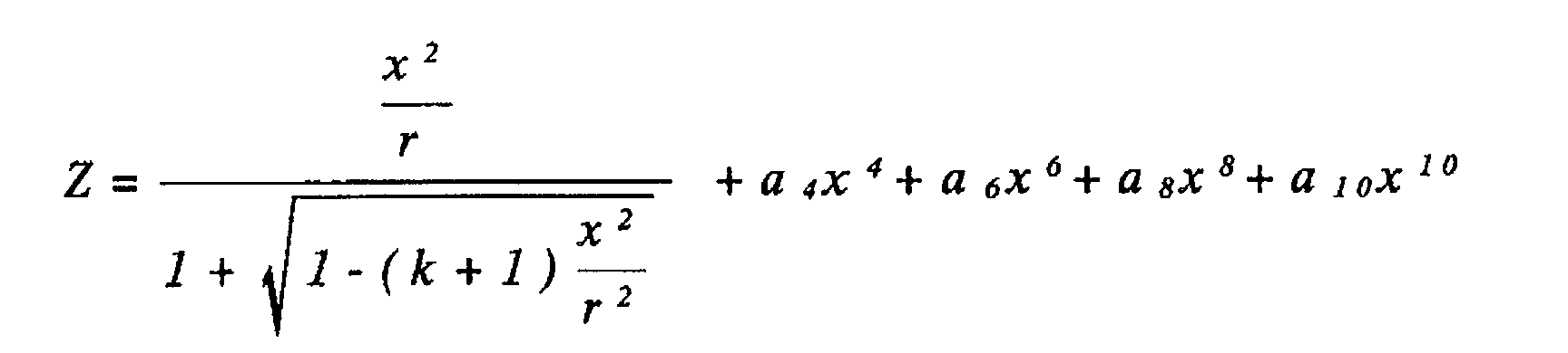
- the optical axis direction is taken as a Z-axis
- the direction perpendicular to the optical axis is taken as an X-axis
- the traveling direction of light is defined to be positive
- the shape of the aspheric face of the lens is represented by a following expression (Eq 1): where, each of k, a 4 , a 6 , a 8 and a 10 is an asp herical factor.
- Fig. 2 shows Example 1 of the present invention.
- the diaphragm 3 was provided in the vicinity of the second face of the first lens 1 and the light quantity control plate 4 was provided between the diaphragm 3 and the first face of the second lens 2.
- Fig. 3 shows the spherical aberration, the astigmatism, and the distortion aberration in the image pickup lens of Example 1. According to the figure, it is clear that each value of the spherical aberration, the astigmatism and the distortion aberration is almost satisfactory so that a sufficient optical characteristic can be obtained.
- Fig. 4 shows Example 2 of the present invention.
- Example 2 as in the image pickup lens of the first embodiment shown in Fig. 1, the diaphragm 3 was provided in the vicinity of the second face of the first lens 1.
- Fig. 5 shows the spherical aberration, the astigmatism, and the distortion aberration in the image pickup lens of Example 2. According to the figure, it is clear that each value of the spherical aberration, the astigmatism and the distortion aberration is almost satisfactory so that a sufficient optical characteristic can be obtained.
- Fig. 6 shows Example 3 of the present invention.
- the diaphragm 3 was provided in the vicinity of the second face of the first lens 1 and the light quantity control plate 4 was provided between the diaphragm 3 and the first face of the second lens 2.
- Fig. 7 shows the spherical aberration, the astigmatism, and the distortion aberration in the image pickup lens of Example 3. According to the figure, it is clear that each value of the spherical aberration, the astigmatism and the distortion aberration is almost satisfactory so that a sufficient optical characteristic can be obtained.
- Fig. 8 shows Example 4 of the present invention.
- Example 4 as in the image pickup lens of the first embodiment shown in Fig. 1, the diaphragm 3 was provided in the vicinity of the second face of the first lens 1.
- Fig. 9 shows the spherical aberration, the astigmatism, and the distortion aberration in the image pickup lens of Example 4. According to the figure, it is clear that each value of the spherical aberration, the astigmatism and the distortion aberration is almost satisfactory so that a sufficient optical characteristic can be obtained.
- Fig. 10 shows Example 5 of the present invention.
- the diaphragm 3 was provided in the vicinity of the second face of the first lens 1 and the light quantity control plate 4 was provided between the diaphragm 3 and the first face of the second lens 2.
- the first face of the second lens 2 is to be the spherical face.
- Fig. 11 shows the spherical aberration, the astigmatism, and the distortion aberration in the image pickup lens of Example 5. According to the figure, it is clear that each value of the spherical aberration, the astigmatism and the distortion aberration is almost satisfactory so that a sufficient optical characteristic can be obtained.
- the image pickup lens according to one aspect of the present invention through satisfying the expressions (1) and (2), the distance between the exit pupil and the image pickup surface (sensor) can be maintained thereby to increase the telecentricity.
- the distance between the exit pupil and the image pickup surface (sensor) can be maintained thereby to increase the telecentricity.
- it enables effective use of the light.
- a diaphragm is provided in the vicinity of the first lens 1 in between the first lens 1 and the second lens.
- the second lens is provided to be the meniscus lens having a positive power with the convex face facing the image pickup surface side. Therefore, the telecentricity can be effectively maintained and the coma aberration and the distortion aberration can be effectively corrected.
- the first lens and the second lens are made of a resin material and, at the same time, at least one face of the first lens and the second lens is formed into an aspherical face. Therefore, a high optical characteristic can be maintained while maintaining the productivity.
Landscapes
- Physics & Mathematics (AREA)
- General Physics & Mathematics (AREA)
- Optics & Photonics (AREA)
- Lenses (AREA)
Abstract
(1) 4 x f2 ≧ f1 ≧ f2
(2) 1.5 x f 1 ≧ f2 ≧ 0.9 x f 1
where,
f 1 : focal length of the whole lens system
f1: focal length of the first lens
f2: focal length of the second lens.
Description
f 1 : focal length of the whole lens system
f1 : focal length of the first lens
f2 : focal length of the second lens.
| Face | Radius r of Curvature | Distance d | Refractive Index nd | Abbe Constant ν d |
| (1) First face of First lens | 1.538 | 1.0000 | 1.52 | 56.0 |
| (2) Second face of First lens | 1.739 | 0.0500 | ||
| (3) Diaphragm | 0.000 | 0.1500 | ||
| (4) Light quantity control plate | 0.000 | 0.1000 | ||
| (5) First face of Second lens | -10.000 | 1.0000 | 1.52 | 56.0 |
| (6) Second face of Second lens | - 1.435 | 0.0000 | ||
| (7) First face of Cover glass | 0.0000 | 0.9000 | 1.516 | 64.0 |
| (8) Second face of Cover glass | 0.000 | 1.5673 | ||
| (9) Image pickup surface | 0.000 |
| Aspherical Factor | |||||
| Face | K | a4 | a6 | a8 | a10 |
| 1 | 0.00e+00 | 9.47e-03 | 1.51e-02 | -1.79e-02 | 1.84e-02 |
| 2 | 3.88e+00 | -1.10e-02 | 9.20e-03 | 0.00e+00 | 0.00e+00 |
| 5 | 0.00e+00 | -1.01e-01 | 1.45e-01 | -7.45e-01 | 0.00e+00 |
| 6 | 5.39e-01 | 1.31e-02 | -4.82e-02 | 6.52e-02 | -5.61e-02 |
| Face | Radius r of Curvature | Distance d | Refractive Index nd | Abbe Constant ν d |
| (1) First face of First lens | 1.405 | 1.1000 | 1.52 | 56.0 |
| (2) Second face of First lens | 1.667 | 0.0500 | ||
| (3) Diaphragm | 0.000 | 0.2500 | ||
| (4) First face of Second lens | -20.000 | 1.1000 | 1.52 | 56.0 |
| (5) Second face of Second lens | -1.580 | 0.0000 | ||
| (6) First face of Cover glass | 0.0000 | 0.9000 | 1.516 | 64.0 |
| (7) Second face of Cover glass | 0.000 | 1.2489 | ||
| (8) Image pickup surface | 0.000 |
| Aspherical Factor | |||||
| Face | K | a4 | a6 | a8 | a10 |
| 1 | 0.00e+00 | 2.91e-03 | 2.17e-02 | -2.32e-02 | 1.88e-02 |
| 2 | 6.61e+00 | -8.36e-02 | -3.57e-01 | 0.00e+00 | 0.00e+00 |
| 4 | 0.00e+00 | -9.21e-02 | -2.82e-02 | -2.25e-01 | 0.00e+00 |
| 5 | 9.12e-01 | 5.96e-03 | -1.69e-02 | 1.88e-02 | -1.57e-02 |
| Face | Radius r of Curvature | Distance d | Refractive Index nd | Abbe Constant ν d |
| (1) First face of First lens | 1.418 | 1.1500 | 1.54 | 56.0 |
| (2) Second face of First lens | 2.381 | 0.0500 | ||
| (3) Diaphragm | 0.000 | 0.0500 | ||
| (4) Light quantity control plate | 0.000 | 0.2000 | ||
| (5) First face of Second lens | -4.878 | 1.1500 | 1.54 | 56.0 |
| (6) Second face of Second lens | -1.575 | 0.0000 | ||
| (7) First face of Cover glass | 0.0000 | 0.7000 | 1.516 | 64.0 |
| (8) Second face of Cover glass | 0.000 | 1.1544 | ||
| (9) Image pickup surface | 0.000 |
| Face | K | a4 | a6 | a8 | a10 |
| 1 | 0.00e+00 | 8.06e-03 | -2.65e-03 | 1.51e-02 | 0.00e+00 |
| 2 | 1.70e+00 | 3.19e-02 | -1.47e-02 | 0.00e+00 | 0.00e+00 |
| 5 | 0.00e+00 | -1.26e-01 | -1.72e-01 | -4.59e-01 | 0.00e+00 |
| 6 | 7.16e-01 | 2.22e-02 | -3.37e-02 | 3.33e-02 | -1.90e-02 |
f 1 = 3.00 mm, f1 = 4.61 mm, f2 = 4.15 mm, F No = 2.8
| Face | Radius r of Curvature | Distance d | Refractive Index nd | Abbe Constant νd |
| (1) First face of First lens | 1.405 | 1.0000 | 1.52 | 56.0 |
| (2) Second face of First lens | 2.525 | 0.0500 | ||
| (3) Diaphragm | 0.000 | 0.2500 | ||
| (4) First face of Second lens | -5.438 | 1.1000 | 1.52 | 56.0 |
| (5) Second face of Second lens | -1.663 | 0.0000 | ||
| (6) First face of | 0.0000 | 0.9000 | 1.516 | 64.0 |
| Cover glass | ||
| (7) Second face of Cover glass | 0.000 | 1.1486 |
| (8) Image pickup surface | 0.000 |
| Aspherical Factor | |||||
| Face | K | a4 | a6 | a8 | a10 |
| 1 | 0.00e+00 | -2.86e-03 | 2.76e-02 | -3.25e-02 | 1.83e-02 |
| 2 | -6.80e-02 | -1.29e-02 | -6.55e-02 | 0.00e+00 | 0.00e+00 |
| 4 | 0.00e+00 | -1.94e-01 | 1.56e-01 | -1.77e+00 | 0.00e+00 |
| 5 | 1.09e+00 | 7.06e-03 | -1.88e-02 | 2.62e-02 | -2.21e-02 |
f 1 = 3.09 mm, f1 = 9.35 mm, f2 = 3.07 mm, F No = 2.8
| Face | Radius r of Curvature | Distance d | Refractive Index nd | Abbe Constant νd |
| (1) First face of First lens | 1.538 | 1.0000 | 1.52 | 56.0 |
| (2) Second face of First lens | 1.739 | 0.0700 | ||
| (3) Diaphragm | 0.000 | 0.1000 | ||
| (4) Light quantity control plate | 0.000 | 0.1300 | ||
| (5) First face of Second lens | -10.000 | 1.0000 | 1.52 | 56.0 |
| (6) Second face of Second lens | -1.435 | 0.0000 | ||
| (7) First face of Cover glass | 0.0000 | 0.9000 | 1.516 | 64.0 |
| (8) Second face of Cover glass | 0.000 | 1.5673 | ||
| (9) Image pickup surface | 0.000 |
| Aspherical Factor | |||||
| Face | k | a4 | a6 | a8 | a10 |
| 1 | 0.00e+00 | -8.10e-04 | 5.87e-02 | -6.66e-02 | 4.54e-02 |
| 2 | 8.11e+00 | -3.45e-02 | -3.54e-01 | 0.00e+00 | 0.00e+00 |
| 6 | 2.53e-01 | -9.79e-03 | 1.44e-02 | -1.76e-02 | -2.13e-03 |
Claims (4)
- An image pickup lens comprising a first lens which is a meniscus lens having a positive power with its convex face facing an object side, a diaphragm, and a second lens which is a lens having a positive power with a strong convex face facing an image pickup surface side being provided in order from the object side, wherein said first lens and said second lens satisfy a condition represented by following expressions:f 1 : focal length of the whole lens systemf1 : focal length of said first lensf2 : focal length of said second lens.
- An image pickup lens according to claim 1, wherein said diaphragm is placed in the vicinity of said first lens in between said first lens and said second lens.
- An image pickup lens according to claim 1 or claim 2, wherein said second lens is a meniscus lens with its convex face facing an image pickup surface side.
- An image pickup lens according to any one of claims 1 to 3, wherein said first lens and said second lens are made of a resin material and at least one face of said first lens and said second lens is formed into an aspherical face.
Applications Claiming Priority (2)
| Application Number | Priority Date | Filing Date | Title |
|---|---|---|---|
| JP2002030611 | 2002-02-07 | ||
| JP2002030611A JP3595308B2 (en) | 2002-02-07 | 2002-02-07 | Imaging lens |
Publications (2)
| Publication Number | Publication Date |
|---|---|
| EP1335227A2 true EP1335227A2 (en) | 2003-08-13 |
| EP1335227A3 EP1335227A3 (en) | 2005-01-12 |
Family
ID=27606511
Family Applications (1)
| Application Number | Title | Priority Date | Filing Date |
|---|---|---|---|
| EP03250660A Ceased EP1335227A3 (en) | 2002-02-07 | 2003-02-01 | Image pickup lens |
Country Status (3)
| Country | Link |
|---|---|
| US (1) | US7139134B2 (en) |
| EP (1) | EP1335227A3 (en) |
| JP (1) | JP3595308B2 (en) |
Cited By (1)
| Publication number | Priority date | Publication date | Assignee | Title |
|---|---|---|---|---|
| CN111931659A (en) * | 2018-08-21 | 2020-11-13 | 深圳市汇顶科技股份有限公司 | Lens system, fingerprint identification device and terminal equipment |
Families Citing this family (9)
| Publication number | Priority date | Publication date | Assignee | Title |
|---|---|---|---|---|
| JP2003149549A (en) * | 2001-11-16 | 2003-05-21 | Enplas Corp | Image pickup lens |
| US6813095B2 (en) * | 2003-03-19 | 2004-11-02 | E-Pin Optical Industry Co., Ltd. | Optical image pick-up lens |
| US6836382B2 (en) * | 2003-05-09 | 2004-12-28 | Alex Ning | Imaging module |
| JP2005140869A (en) * | 2003-11-04 | 2005-06-02 | Nidec Copal Corp | Reading lens |
| JP4224789B2 (en) * | 2004-03-01 | 2009-02-18 | ソニー株式会社 | Imaging device |
| JP2006098504A (en) * | 2004-09-28 | 2006-04-13 | Matsushita Electric Ind Co Ltd | Shooting lens |
| WO2006035990A1 (en) * | 2004-09-28 | 2006-04-06 | Matsushita Electric Industrial Co., Ltd. | Imaging lens |
| JP4861797B2 (en) | 2006-11-21 | 2012-01-25 | 株式会社エンプラス | Imaging lens and imaging apparatus provided with the same |
| JP2009075437A (en) * | 2007-09-21 | 2009-04-09 | Kantatsu Co Ltd | Imaging lens |
Family Cites Families (14)
| Publication number | Priority date | Publication date | Assignee | Title |
|---|---|---|---|---|
| JPH03116109A (en) | 1989-09-29 | 1991-05-17 | Hoya Corp | Aspherical lens system of two-group, two-element constitution |
| JPH06230278A (en) | 1993-01-29 | 1994-08-19 | Konica Corp | Lens system of symmetric constitution with two groups and two lenses |
| JPH07181379A (en) | 1993-12-24 | 1995-07-21 | Asahi Optical Co Ltd | Imaging lens system |
| JPH07287164A (en) | 1994-04-15 | 1995-10-31 | Kyocera Corp | Reduction imaging lens |
| US5600493A (en) * | 1994-12-28 | 1997-02-04 | Fuji Photo Optical Co., Ltd. | Finite conjugate lens system |
| JPH10111452A (en) | 1996-10-07 | 1998-04-28 | Asahi Optical Co Ltd | Endoscope objective lens |
| JPH10206725A (en) | 1997-01-20 | 1998-08-07 | Fuji Photo Film Co Ltd | Photographing lens and camera using the same |
| JP3767182B2 (en) | 1998-07-17 | 2006-04-19 | ソニー株式会社 | Imaging lens and lens system |
| JP2000089107A (en) * | 1998-09-17 | 2000-03-31 | Fuji Photo Optical Co Ltd | Image reading lens |
| JP2000227547A (en) * | 1999-02-05 | 2000-08-15 | Fuji Photo Film Co Ltd | Photographic lens and camera using the same |
| US8073712B2 (en) * | 1999-04-02 | 2011-12-06 | Cybernet Systems Corporation | Method for consolidating medical records through the world wide web |
| JP3393186B2 (en) * | 1999-12-22 | 2003-04-07 | マイルストーン株式会社 | Imaging lens |
| JP2002023050A (en) | 2000-07-06 | 2002-01-23 | Fuji Photo Film Co Ltd | Photographing lens |
| US20030065738A1 (en) * | 2001-10-01 | 2003-04-03 | Thumb Logic, Inc. | Wireless information systems and methods |
-
2002
- 2002-02-07 JP JP2002030611A patent/JP3595308B2/en not_active Expired - Fee Related
-
2003
- 2003-01-31 US US10/356,280 patent/US7139134B2/en not_active Expired - Fee Related
- 2003-02-01 EP EP03250660A patent/EP1335227A3/en not_active Ceased
Cited By (2)
| Publication number | Priority date | Publication date | Assignee | Title |
|---|---|---|---|---|
| CN111931659A (en) * | 2018-08-21 | 2020-11-13 | 深圳市汇顶科技股份有限公司 | Lens system, fingerprint identification device and terminal equipment |
| US11366290B2 (en) | 2018-08-21 | 2022-06-21 | Shenzhen GOODIX Technology Co., Ltd. | Lens system, fingerprint identification apparatus and terminal device |
Also Published As
| Publication number | Publication date |
|---|---|
| JP3595308B2 (en) | 2004-12-02 |
| EP1335227A3 (en) | 2005-01-12 |
| JP2003232991A (en) | 2003-08-22 |
| US20030169362A1 (en) | 2003-09-11 |
| US7139134B2 (en) | 2006-11-21 |
Similar Documents
| Publication | Publication Date | Title |
|---|---|---|
| US7196856B2 (en) | Imaging lens system | |
| US7385770B2 (en) | Imaging lens system | |
| EP1887400B1 (en) | Imaging lens having a two-lens structure | |
| US6560043B1 (en) | Image pickup lens system | |
| US7450323B2 (en) | Imaging lens and imaging device including the imaging lens | |
| EP1995620A1 (en) | Imaging lens | |
| EP1426805B1 (en) | Imaging lens system | |
| EP1650591B1 (en) | Imaging lens system with two positive lenses | |
| CN105652422B (en) | Zoom lens and photographic device | |
| US6987625B2 (en) | Imaging lens system | |
| EP1650592B1 (en) | Compact two-lens objective | |
| US7139134B2 (en) | Image pickup lens | |
| EP2065744A1 (en) | Dual lens objective | |
| EP1367422A2 (en) | Wide-angle optical system for solid image pickup element | |
| JP4171989B2 (en) | Shooting lens system | |
| EP1382986B1 (en) | Imaging lens system | |
| JPH11295592A (en) | Image forming lens | |
| JP3820213B2 (en) | Imaging lens | |
| JP2005091513A (en) | Optical lens for imaging camera | |
| JP3593530B2 (en) | Imaging lens | |
| EP1801629A1 (en) | Wide-angle optical system for solid image pickup device | |
| JP2004199092A (en) | Imaging lens | |
| JP4758168B2 (en) | Imaging lens |
Legal Events
| Date | Code | Title | Description |
|---|---|---|---|
| PUAI | Public reference made under article 153(3) epc to a published international application that has entered the european phase |
Free format text: ORIGINAL CODE: 0009012 |
|
| AK | Designated contracting states |
Designated state(s): AT BE BG CH CY CZ DE DK EE ES FI FR GB GR HU IE IT LI LU MC NL PT SE SI SK TR |
|
| AX | Request for extension of the european patent |
Extension state: AL LT LV MK RO |
|
| PUAL | Search report despatched |
Free format text: ORIGINAL CODE: 0009013 |
|
| AK | Designated contracting states |
Kind code of ref document: A3 Designated state(s): AT BE BG CH CY CZ DE DK EE ES FI FR GB GR HU IE IT LI LU MC NL PT SE SI SK TR |
|
| AX | Request for extension of the european patent |
Extension state: AL LT LV MK RO |
|
| AKX | Designation fees paid | ||
| 17P | Request for examination filed |
Effective date: 20050830 |
|
| RBV | Designated contracting states (corrected) |
Designated state(s): AT BE BG CH CY CZ DE DK EE ES FI FR GB GR HU IE IT LI LU MC NL PT SE SI SK TR |
|
| REG | Reference to a national code |
Ref country code: DE Ref legal event code: 8566 |
|
| 17Q | First examination report despatched |
Effective date: 20060511 |
|
| STAA | Information on the status of an ep patent application or granted ep patent |
Free format text: STATUS: THE APPLICATION HAS BEEN REFUSED |
|
| 18R | Application refused |
Effective date: 20090402 |