EP1334879A1 - Vehicle body structure with head protecting airbag - Google Patents
Vehicle body structure with head protecting airbag Download PDFInfo
- Publication number
- EP1334879A1 EP1334879A1 EP03002406A EP03002406A EP1334879A1 EP 1334879 A1 EP1334879 A1 EP 1334879A1 EP 03002406 A EP03002406 A EP 03002406A EP 03002406 A EP03002406 A EP 03002406A EP 1334879 A1 EP1334879 A1 EP 1334879A1
- Authority
- EP
- European Patent Office
- Prior art keywords
- vehicle body
- roof lining
- pillar garnish
- airbag
- back surface
- Prior art date
- Legal status (The legal status is an assumption and is not a legal conclusion. Google has not performed a legal analysis and makes no representation as to the accuracy of the status listed.)
- Granted
Links
- 235000021189 garnishes Nutrition 0.000 claims abstract description 75
- 239000005357 flat glass Substances 0.000 claims abstract description 28
- 238000010276 construction Methods 0.000 description 10
- 239000000463 material Substances 0.000 description 4
- 239000004831 Hot glue Substances 0.000 description 3
- 238000005452 bending Methods 0.000 description 1
- 238000000034 method Methods 0.000 description 1
Images


Classifications
-
- B—PERFORMING OPERATIONS; TRANSPORTING
- B60—VEHICLES IN GENERAL
- B60R—VEHICLES, VEHICLE FITTINGS, OR VEHICLE PARTS, NOT OTHERWISE PROVIDED FOR
- B60R21/00—Arrangements or fittings on vehicles for protecting or preventing injuries to occupants or pedestrians in case of accidents or other traffic risks
- B60R21/02—Occupant safety arrangements or fittings, e.g. crash pads
- B60R21/16—Inflatable occupant restraints or confinements designed to inflate upon impact or impending impact, e.g. air bags
- B60R21/20—Arrangements for storing inflatable members in their non-use or deflated condition; Arrangement or mounting of air bag modules or components
- B60R21/213—Arrangements for storing inflatable members in their non-use or deflated condition; Arrangement or mounting of air bag modules or components in vehicle roof frames or pillars
-
- B—PERFORMING OPERATIONS; TRANSPORTING
- B60—VEHICLES IN GENERAL
- B60R—VEHICLES, VEHICLE FITTINGS, OR VEHICLE PARTS, NOT OTHERWISE PROVIDED FOR
- B60R13/00—Elements for body-finishing, identifying, or decorating; Arrangements or adaptations for advertising purposes
- B60R13/02—Internal Trim mouldings ; Internal Ledges; Wall liners for passenger compartments; Roof liners
- B60R13/0237—Side or rear panels
- B60R13/025—Pillars; Roof rails
-
- B—PERFORMING OPERATIONS; TRANSPORTING
- B60—VEHICLES IN GENERAL
- B60R—VEHICLES, VEHICLE FITTINGS, OR VEHICLE PARTS, NOT OTHERWISE PROVIDED FOR
- B60R21/00—Arrangements or fittings on vehicles for protecting or preventing injuries to occupants or pedestrians in case of accidents or other traffic risks
- B60R21/02—Occupant safety arrangements or fittings, e.g. crash pads
- B60R21/16—Inflatable occupant restraints or confinements designed to inflate upon impact or impending impact, e.g. air bags
- B60R21/23—Inflatable members
- B60R21/231—Inflatable members characterised by their shape, construction or spatial configuration
- B60R21/232—Curtain-type airbags deploying mainly in a vertical direction from their top edge
-
- B—PERFORMING OPERATIONS; TRANSPORTING
- B60—VEHICLES IN GENERAL
- B60R—VEHICLES, VEHICLE FITTINGS, OR VEHICLE PARTS, NOT OTHERWISE PROVIDED FOR
- B60R13/00—Elements for body-finishing, identifying, or decorating; Arrangements or adaptations for advertising purposes
- B60R13/02—Internal Trim mouldings ; Internal Ledges; Wall liners for passenger compartments; Roof liners
- B60R13/0206—Arrangements of fasteners and clips specially adapted for attaching inner vehicle liners or mouldings
-
- B—PERFORMING OPERATIONS; TRANSPORTING
- B60—VEHICLES IN GENERAL
- B60R—VEHICLES, VEHICLE FITTINGS, OR VEHICLE PARTS, NOT OTHERWISE PROVIDED FOR
- B60R13/00—Elements for body-finishing, identifying, or decorating; Arrangements or adaptations for advertising purposes
- B60R13/02—Internal Trim mouldings ; Internal Ledges; Wall liners for passenger compartments; Roof liners
- B60R13/0212—Roof or head liners
- B60R13/0225—Roof or head liners self supporting head liners
-
- B—PERFORMING OPERATIONS; TRANSPORTING
- B60—VEHICLES IN GENERAL
- B60R—VEHICLES, VEHICLE FITTINGS, OR VEHICLE PARTS, NOT OTHERWISE PROVIDED FOR
- B60R13/00—Elements for body-finishing, identifying, or decorating; Arrangements or adaptations for advertising purposes
- B60R13/02—Internal Trim mouldings ; Internal Ledges; Wall liners for passenger compartments; Roof liners
- B60R2013/0293—Connection or positioning of adjacent panels
-
- B—PERFORMING OPERATIONS; TRANSPORTING
- B60—VEHICLES IN GENERAL
- B60R—VEHICLES, VEHICLE FITTINGS, OR VEHICLE PARTS, NOT OTHERWISE PROVIDED FOR
- B60R21/00—Arrangements or fittings on vehicles for protecting or preventing injuries to occupants or pedestrians in case of accidents or other traffic risks
- B60R21/02—Occupant safety arrangements or fittings, e.g. crash pads
- B60R21/16—Inflatable occupant restraints or confinements designed to inflate upon impact or impending impact, e.g. air bags
- B60R21/20—Arrangements for storing inflatable members in their non-use or deflated condition; Arrangement or mounting of air bag modules or components
- B60R21/215—Arrangements for storing inflatable members in their non-use or deflated condition; Arrangement or mounting of air bag modules or components characterised by the covers for the inflatable member
- B60R2021/21543—Arrangements for storing inflatable members in their non-use or deflated condition; Arrangement or mounting of air bag modules or components characterised by the covers for the inflatable member with emblems
-
- B—PERFORMING OPERATIONS; TRANSPORTING
- B60—VEHICLES IN GENERAL
- B60R—VEHICLES, VEHICLE FITTINGS, OR VEHICLE PARTS, NOT OTHERWISE PROVIDED FOR
- B60R21/00—Arrangements or fittings on vehicles for protecting or preventing injuries to occupants or pedestrians in case of accidents or other traffic risks
- B60R21/02—Occupant safety arrangements or fittings, e.g. crash pads
- B60R21/16—Inflatable occupant restraints or confinements designed to inflate upon impact or impending impact, e.g. air bags
- B60R21/23—Inflatable members
- B60R21/231—Inflatable members characterised by their shape, construction or spatial configuration
- B60R2021/23153—Inflatable members characterised by their shape, construction or spatial configuration specially adapted for rear seat passengers
-
- B—PERFORMING OPERATIONS; TRANSPORTING
- B60—VEHICLES IN GENERAL
- B60R—VEHICLES, VEHICLE FITTINGS, OR VEHICLE PARTS, NOT OTHERWISE PROVIDED FOR
- B60R22/00—Safety belts or body harnesses in vehicles
- B60R22/18—Anchoring devices
- B60R22/24—Anchoring devices secured to the side, door, or roof of the vehicle
Definitions
- the present invention relates to a vehicle body structure with a head protecting airbag wherein an airbag is provided on a back surface side of an automotive roof lining, wherein the roof lining is adapted to be dislocated from a rear pillar garnish by virtue of an expansion pressure resulting when the airbag is expanded, and wherein the airbag is allowed to expand into a passenger compartment through a gap so resulting between the rear pillar garnish and the roof lining.
- Pillar garnishes are provided on front pillars, center pillars and rear pillars which support a roof of an automobile as linings. Certain devices have been provided to have a good appearance at an abutment portion where each garnish abuts with another lining material. Known as an example of the devices is JP-B-63-6384 entitled "Automotive Trim Components Joining Portion Structure.”
- a roof lining is provided to the roof supported by the respective pillars as a lining.
- FIG. 8 A vehicle body structure is shown in Fig. 8 in which an airbag is provided on the back surface side of a roof lining, and the details thereof will be described below.
- Fig. 8 is a side view of a conventional vehicle body structure with a head protecting airbag.
- a frame portion 102 of a rear pillar garnish 101 is provided in such a manner as to extend along an upper portion of a rear side window glass frame member, a rear projecting portion 103 of the rear pillar garnish 101 is caused to project upwardly from a rear end of the frame portion 102 until the rear projecting portion reaches a rear window glass 10 4 , a side portion 106 and a rear portion 107 of a roof lining 105 are caused to overlap a back surface of the frame portion 102 and a back surface of the rear projecting portion 103 of the rear pillar garnish 101, respectively, and a head protecting airbag 110 is provided within a space existing between the roof lining 105 and a vehicle body panel.
- reference numeral 108 denotes a rear side window glass.
- Fig. 9 is a side view showing a state in which an airbag of the conventional vehicle body structure with a head protecting airbag is expanded.
- An inflator 111 for the head protecting airbag 110 is activated, and a gas is supplied to an airbag 113 from the inflator 111, whereby the airbag is expanded.
- An expansion pressure is generated by the expansion of the airbag 113, and the side portion 106 of the roof lining 105 is dislocated from the frame portion 102 of the pillar garnish 101 toward the passenger compartment side with the expansion pressure, whereby a gap can be opened between the frame portion 102 of the pillar garnish 101 and the side portion 106 of the roof lining 105.
- the airbag 113 can be expanded into the passenger compartment through the gap so opened so that the head of a rear seat passenger can be protected with the airbag 113 so expanded.
- the rear portion 107 of the roof lining 105 is also caused to extend along the vehicle body panel only with the rear portion 107 being caused to overlap the back surface of the rear projecting portion 103 of the pillar garnish 101.
- an object of the invention is to provide a vehicle body structure with a head protecting airbag in which in the event that the expansion pressure of an airbag is applied to a rear portion of a roof lining, the airbag can be expanded stably through a gap formed between a frame portion of a pillar garnish and a side portion of the roof lining.
- a vehicle body structure with a head protecting airbag includes a rear pillar garnish having a frame portion disposed in such a manner as to extend along an upper portion of a rear side window glass frame member, and a rear projecting portion projecting upwardly from a rear end of said frame portion to a rear window glass, the rear projectingportion being attached to a vehicle body panel via a clip boss; a roof lining having a side portion and a rear portion disposed so as to overlap a back surface of the frame portion and a back surface of the rear projecting portion, respectively; the head protecting airbag disposed on a back surface of the roof lining; and a supporting bracket attached to a back surface of a vicinity of a rear portion of the roof lining, the supporting bracket being attached to the vehicle body panel.
- the supporting bracket is attached to the back surface of the vicinity of the rear portion of the roof lining, and the supporting bracket is attached to the vehiclebodypanel.
- the vicinity of the rear portion of the roof lining can be attached to the vehicle body panel via the supporting bracket.
- the rear portion of the roof lining can be securely left overlapping the back surface of the rear projecting portion of the rear pillar garnish.
- the side portion of the roof lining can be dislocated from the frame portion of the rear pillar garnish with good efficiency with the expansion pressure of the airbag so as to ensure the stable expansion of the airbag.
- a vehicle body structure with a head protecting airbag as set forth in the first aspect of the invention, wherein the supporting bracket is caused to extend rearward toward the rear projecting portion, and wherein a positioning opening in which the clip boss is allowed to fit is formed in an extending portion formed as a result of the rearward extension of the supporting bracket.
- the extending portion of the supporting bracket is caused to extend rearward toward the rear projecting portion, and the positioning opening is formed in the extending portion in which the clip boss is allowed to fit.
- the positioning opening is formed in the extending portion in which the clip boss is allowed to fit.
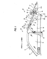
- Fig. 1 is a side view of a vehicle provided with a vehicle body structure with a head protecting airbag according to the invention, as viewed from a passenger compartment side of the vehicle.
- a vehicle 10 comprises a front pillar garnish 11 attached to a passenger compartment side of a front pillar as an interior member, a center pillar garnish 12 attached to a passenger compartment side of a center pillar as an interior member, and a vehicle body structure 20 with a head protecting airbag on a passenger compartment side of a rear pillar.
- reference numeral 14 denotes a windshield; 15: a front side window glass; 16: a rear side window glass; 17: a rear window glass, 18: a front seat belt; and 19: a rear seat belt.
- a frame portion 26 of a rear pillar garnish 25 is provided in such a manner as to extend along an upper portion 23 of a rear side window glass frame member 22 constituting a vehicle body panel 21 shown in Fig. 3, and a rear projecting portion 27 of the rear pillar garnish 25 is allowed to project upwardly from a rear end of the frame portion 26 until it reaches the rear window glass 17. Then, a side portion 31 and a rear portion 32 of a roof lining 30 is caused to overlap a back surface of the frame portion 26 and a back surface of the rear projecting portion 27, respectively, and a supporting bracket 35 is attached to a back surface of the roof lining 30.
- the roof lining 30 is then attached to the vehicle body panel 21 via the supporting bracket 35, and a head protecting airbag 40 is disposed on a back surface side of the roof lining 30.
- a casing 51 for a hanger 50 is integrally formed with the frame portion 26 of the rear pillar garnish 25, and a hook 52 for the hanger 50 is provided on the casing 51.
- the head protecting airbag 40 is constructed as below. Namely, an inflator 41 is disposed on a back surface side of the rear projecting portion 27 of the rear pillar garnish 25, and the inflator 41 is attached to the vehicle body panel 21 with machine screws 41a ... Then, an airbag 42 is attached to a distal end of the inflator 41 and is allowed to extend toward the front of the vehicle body panel 21 along the frame portion 26 of the rear pillar garnish 25. The airbag 42 is then attached to a supporting bracket 43 (shown in Fig. 4), and this supporting bracket 43 is attached to the vehicle body panel 21 with machine screws 44 ...
- Fig. 2 is an enlarged view of a portion of the vehicle body structure 20 with a head protecting airbag which is denoted by reference numeral 2 in Fig. 1.
- the vicinity of the rear portion 32 of the roof lining 30 is attached to the vehicle body panel by attaching the supporting bracket 35 to a back surface of the vicinity of the rear portion 32 of the roof lining 30 with a hot-melt adhesive 36 at a plurality of positions and then attaching the supporting bracket 35 to the vehicle body panel 21 (refer to Fig. 3) with a clip 37.
- the rear projecting portion 27 of the rear pillar garnish 25 is attached to the vehicle body panel 21 by providing a clip boss 28 on the back surface of the rear projecting portion 27 and then attaching the clip boss 28 to the vehicle body panel 21.
- the side portion 31 of the roof lining 30 is caused to overlap the back surface side of the frame portion 26 of the rear pillar garnish 25 and the rear portion 32 of the roof lining 30 is also caused to overlap the back surface side of the rear projecting portion 27 of the rear pillar garnish 25 as the vicinity of the rear portion 32 of the roof lining 30 and the rear projecting portion 27 of the rear pillar garnish 25 are attached to the vehicle body panel 21, respectively, as described above.
- Fig. 3 is a sectional view taken along the line 3-3 shown in Fig. 2.
- the supporting bracket 35 is attached to the back surface 30a of the vicinity of the rear portion 32 of the roof lining 30 with the hot-melt adhesive 36 at the plurality of positions.
- a leg piece 35a is formed at the vicinity of a front end of the supporting bracket 35 and a locking piece 35b is formed at an upper end of the leg piece 35a.
- a base portion 37a of the clip 37 is locked in a locking groove 35c of the locking piece 35b, and a diametrically enlarged portion 37b at a distal end of the clip 37 is caused to project from an attachment hole 21a in the vehicle body panel 21 to thereby lock the clip 37 in the vehicle body panel 21.
- the vicinity of the rear portion 32 of the roof lining 30 can be attached to the vehicle body panel 21 via the supporting bracket 35 by locking the clip 37 to the vehicle body panel 21 so as to attach the supporting bracket 35 to the vehicle body panel 21 as has been described above.
- the supporting bracket 35 is constructed as below. Namely, a bent portion 35d is formed at the center of the supporting bracket 35, and an extending portion 38 is provided such that it extends from the bent portion 35d to the rear of the vehicle body along the vehicle body panel 21.
- a stay 38a is extended from a front end of the extending portion 38 extended to the rear of the vehicle body toward the vehicle body panel 21 so that a distal end of the stay 38a is brought into abutment with the vehicle body panel 21, and a positioning opening 38b is formed substantially in the center of the extending portion 38 so that the clip boss 28 can be fitted there into.
- the extending portion 38 can be supported by the stay 38a by allowing the distal end of the stay 38a to abut with the vehicle body panel 21.
- the clip boss 28 is a hollow projecting body that is formed integrally with the rear projecting portion 27 of the rear pillar garnish 25 in such a manner as to project from the rear projecting portion 27 toward the vehicle body panel 21.
- stepped portions 29, 29 are formed at a proximal end of the clip boss 28, and locking holes 29a, 29a are formed in the stepped portions 29, 29, respectively.
- a projecting piece 28b is formed on an inner circumference of a distal end 28a of the clip boss 28 in such a manner as to extend radially inwardly.
- An opening 27a is formed in the rear projecting portion 27 of the rear pillar garnish 25 by forming the clip boss 28 integrally with the rear projecting portion of the rear pillar garnish 25.
- a grommet 61 is inserted into the distal end 28a of the clip boss 28 such that the projecting piece 28b fits in an annular groove 61a of the grommet 61, whereby a diametrically expanded portion 61b at a distal end of the grommet 61 is allowed to project from the distal end 28a of the clip boss 28.
- the clip boss 28 is inserted into the opening 27a of the rear projecting portion 27 and the diametrically expanded portion 61b at the distal end of the grommet 61 is allowed to project from the attaching hole 21b in the vehicle body panel 21.
- the grommet 61 can be locked in the vehicle body panel 21, whereby the clip boss 28 can be attached to the vehicle body panel 21. Accordingly, the rear projecting portion 27 of the rear pillar garnish 25 can be attached to the vehicle body panel 21 via the clip boss 28.
- hooks 64, 64 projects from both ends of the cap 62 are allowed to project from the locking holes 29a, 29a formed in the stepped portions 29, 29 of the clip boss 28.
- the hooks 64, 64 are locked at the stepped portions 29, 29, respectively, whereby the cap 62 can be locked in the opening 27a of the rear projecting portion 27, the removal of the distal end 63a of the clip 63 from the through hole 61c in the grommet 61 being thereby prevented.
- the roof lining 30 is attached to the vehicle body panel 21 via the supporting bracket 35, and when the rear projecting portion 27 of the rear pillar garnish 25 is attached to the vehicle body panel 21 via the clip boss 28, the rear portion 32 of the roof lining 30 overlaps the back surface 27b of the rear projecting portion 27.
- the supporting bracket 35 is attached to the back surface 30a of the vicinity of the rear portion 32 of the roof lining 30 with the hot-melt adhesive 36, and the base portion 37a of the clip 37 is attached to the locking piece 35b of the supporting bracket 35, while the diametrically expanded portion 37b at the distal end of the clip 37 is inserted into the attaching hole 21a of the vehicle body panel 21 so that the diametrically expanded portion 37b is allowed to project from the attaching hole 21a.
- the vicinity of the rear portion 32 of the roof lining 30 is attached to the vehicle body panel 21 via the supporting bracket 35.
- the grommet 61 is inserted into the distal end 28a of the clip boss 28 and the annular groove 61a of the grommet 61 is fitted on the projecting piece 28b.
- the clip boss 28 is inserted into the positioning opening 38b in the supporting bracket 35 (the extending portion 38).
- the clip boss 28 can be positioned at the proper position by using the positioning opening 38b, and the diametrically expanded portion 61b at the distal end of the grommet 61 can simply be inserted into the attaching hole 21b in the vehicle body panel 21.
- the opening 27a of the rear projecting portion 27 is closed with the cap 62, whereby the distal end 63a of the clip 63 is allowed to project from the through hole 61c of the grommet 61 and the hooks 64, 64 are locked in the locking holes 29a, 29a in the stepped portions 29, 29.
- the rear projecting portion 27 of the rear pillar garnish can be attached to the vehicle body panel 21 via the clip boss 28.
- the clip boss 28 can be positioned at the proper position using the positioning opening 38b by inserting the clip boss 28 into the positioning opening 38b of the supporting bracket 35.
- the rear pillar garnish 25 can simply be assembled to the vehicle body panel 21.
- the hanger 50 can be provided above the rear side window glass 16 by providing the hanger 50 in the frame portion 26 of the rear pillar garnish 26. With this hanger 50, something like the clothes of a passenger can be hooked on the hook 52 which is normally stored in the casing 51 of the hanger 50 by pulling it out of the casing 51.
- Fig. 4 is a sectional view taken along the line 4-4 in Fig. 1 and shows the relationship between the frame portion 26 of the rear pillar garnish 25 and the hanger 50.
- the casing 51 for the hanger 50 is integrally formed with the frame portion 26 of the rear pillar garnish 25 in a recessed fashion in which the casing 51 is recessed upwardly, and the casing 51 is attached to the upper portion 23 of the side window glass frame member 22 with a machine screw 56, the hook 52 for the hanger 50 being provided on the casing 51 via a pin 53 in such a manner as to freely swing around the pin 53 in directions denoted by an arrow 1 ⁇ .
- the hook 52 is allowed to swing around the pin 53 to move between a stored position (a position shown by a solid line) where the hook 52 is stored in the casing 51 and an in-use position (a position shown by an imaginary line) where the hook 52 is pulled out of the casing 51.
- the pillar garnish 25 can rigidly be attached to the upper portion 23 of the side window glass frame member 22 by forming the casing 51 for the hanger 50 integrally with the frame portion 26 of the rear pillar garnish 25 and attaching the casing 51 to the upper portion 23 of the side window glass frame member 22 with the machine screw 56.
- the number of components can be reduced by forming the casing 51 for the hanger 50 integrally with the frame portion 26 of the rear pillar garnish 25.
- the number of manhours required for assembling can be attempted to be reduced by making simple the construction of the vehicle body structure 20 with a head protecting airbag through the reduction in the number of components involved.
- Fig. 5 is a view as viewed in a direction indicated by an arrow 5 in Fig. 4.
- the casing 51 for the hanger 50 is integrally formed with the frame portion 26 of the rear pillar garnish 25 in the recessed fashion, bosses 54, 54 are formed on side walls 50a, 50a of the casing 51 formed in the recessed fashion, respectively, and both ends of the pin 53 are attached to the bosses 54, 54 formed on the side walls 50a, 50a, whereby the pin 53 is attached to a base portion 52a of the hook 52.
- An open edge 51a of the casing 51 is connected to the frame portion 26 of the rear pillar garnish 25 by forming the casing 51 for the hanger 50 integrally with the frame portion 26 of the rear pillar garnish 25 in the recessed fashion in which the casing 51 is recessed upwardly.
- the casing 51 is provided with a ceiling portion 55, and the machine screw 56 is inserted into a through hole 55a in the ceiling 55, so that the machine screw 56 is screwed into a grommet 57 that has been assembled to the casing 51 in advance, whereby the grommet 57 can be attached to the casing 51 rigidly.
- the rear pillar garnish 25 can be attached to the upper portion 23 of the rear side window glass frame member 22 together with the casing 51 by inserting the grommet 57 into an attaching hole in the upper portion 23 of the rear side window glass frame member 22.
- a head portion 56a of the machine screw 56 can also be covered with the cover plate 58.
- a left locking hole 55b is formed at a left end of the ceiling portion 55 and a right locking hole 55c is formed at a right end thereof, so that a locking piece 58a of the cover plate 58 is locked in the left locking hole 55b and a locking pawl 58b of the cover plate 58 is locked in the right locking hole 55c, whereby the cover plate 58 can be fixed to the ceiling portion 55.
- the ceiling portion 55 can be covered with the cover plate 58 and the head portion 56a of the machine screw 56 can be covered with the cover plate 58.
- the pin 53 is provided in the casing 51 at the vicinity of a side of the open edge 51a which faces the outside of the vehicle body (refer to Fig. 5), so that the base portion 52a of the hook 52 is supported by the pin. 53, whereby the hook 52 is allowed to freely swing around the pin 53 in the directions indicated by the arrows 1 ⁇ .
- a boss 51c is provided on a stepped portion 51b provided on the casing 51 at the vicinity of the side of the open edge 51a which faces the outside of the vehicle body, and an upper end of a plate spring 59 is fixed to an upper surface of the boss 51c with a machine screw 66, whereas a distal end 59a of the plate spring 59 is inserted into the casing 51 through a through hole 51d in the casing 51, so that the distal end 59a of the plate spring 59 so inserted is caused to abut with the base portion 52a (a first pressing surface 52b) of the hook 52, whereby the plate spring 59 is held in a state in which the plate spring 59 is bent substantially into a U-shape.
- the hook 52 can be held at the stored position (the position shown by the solid line) by virtue of the biasing force of the plate spring 59.
- a hooking portion 52d formed at a distal end of the hook 52 by bending a distal end portion of the hook 52 can be stored in the interior of the casing 51 when the hook 52 is disposed at a stored position. As this occurs, the hook 52 can be held stably at the stored position in the interior of the casing 51 by allowing the hooking portion 52d to abut with a stopper 67.
- stopper 67 is attached to the cover plate 58.
- the finger When using the hook 52, the finger is hooked on a recess 52e in the hooking portion 52d to swing the hook 52 to the in-use position (the position shown by the imaginary line) against the biasing force of the plate spring 59.
- the hook 52 can be held at the in-use position by allowing the base portion 52a (a second pressing surface 52c) of the hook 52 to be pressed against by the plate spring 59. In this state, something like the clothes of the passenger can be hooked on the hooking portion 52d of the hook 52.
- the side portion 31 of the roof lining 30 overlaps the back surface 26a (the back surface of the rear pillar garnish 25) of the frame portion 26 of the rear pillar garnish 25 which is integrally formed with the casing 51 at a location on a passenger compartment side thereof.
- the airbag 42 is disposed on a back surface 30a of the roof lining 30, and the airbag 42 is then attached to the supporting bracket 43, which is then attached to the upper portion 23 of the side window glass frame member 22 with the machine screws 41 (shown in Fig. 1).
- a cushion material 68 is provided on the frame portion 26 of the rear pillar garnish 25 which is formed integrally with the casing 51 at a location which is situated on a side of the frame portion 26 which faces the outside of the vehicle body, and an edge portion 23a of the side window glass frame member 22 is pressed against the cushion material 68.
- Figs. 6A, 6B are first explanatory views explaining the function of the vehicle body structure with a head protecting airbag according to the invention.
- a gas is supplied to the airbag 42 from the inflator 41, whereby the airbag 42 starts to be expanded, and the expansion pressure of the airbag 42 is applied to the back surface 30a of the roof lining 30 (refer to Fig. 4).
- the side portion 31 of the roof lining 30 needs to be pushed into the passenger compartment side with the expansion pressure of the airbag 42. As this occurs, the expansion pressure of the airbag 42 is also applied to the frame portion 26 of the rear pillar garnish 25 via the side portion 31 of the roof lining 30.
- the casing 51 for the hanger 50 is formed integrally with the frame portion 26 of the rear pillar garnish 25 (refer to Fig. 4), and the casing 51 is attached to the upper portion 23 of the side window glass frame member 22, whereby the frame portion 26 of the rear pillar garnish 25 is rigidly attached to the upper portion 23 of the side window glass frame member 22.
- the pillar garnish 25 when the airbag 42 is expanded, the pillar garnish 25 can be held securely to the upper portion 23 of the side window glass frame member 22.
- the expansion pressure of the airbag 42 is also applied to the rear portion 32 of the roof lining 30.
- the vicinity of the rear portion 32 of the roof lining 30 is constructed to be attached to the vehicle body panel 21 (shown in Fig. 3) via the supporting bracket 35.
- the rear portion 32 of the roof lining 30 can be held in a state in which the rear portion 32 overlaps the back surface 27b of the rear projecting portion 27 of the rear pillar garnish 25.
- the frame portion 26 of the rear pillar garnish 25 can be securely held to the upper portion 23 of the side window glass frame member 22, and furthermore, the rear portion 32 of the roof lining 30 can be held to the back surface 27b side of the rear projecting portion 27 of the rear pillar garnish 25 (shown in Fig. 6A).
- the airbag 42 can be expanded into the passenger compartment through the gap S generated between the frame portion 26 of the rear pillar garnish 25 and the side portion 31 of the roof lining 30.
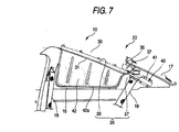
- Fig. 7 is a second explanatory view explaining the function of the vehicle body structure with a head protecting airbag according to the invention.
- the airbag 42 can be expanded into the passenger compartment through the gas S between the frame portion 26 of the rear pillar garnish 25 and the side portion 31 of the roof lining 30, the airbag 42 can be expanded stably, and the performance of the airbag can be exhibited efficiently.
- the frame member 26 of the rear pillar garnish 25 is rigidly attached to the upper portion 23 of the side window glass frame member 22, and furthermore, the vicinity of the rear portion 32 of the roof lining 30 is attached to the vehicle body panel 21 via the supporting bracket 35, even if only either of these two constructions is implemented, or even if only the vicinity of the rear portion 32 of the roof lining 30 is attached to the vehicle body panel 21 via the supporting bracket 35, effectiveness similar to that provided by the embodiment can also be attained.
- the invention is not limited to the construction, and the airbag 42 can be extended as far as the front pillar garnish 11.
- the invention provides the following advantages through the aforesaid constructions.
- the supporting bracket is attached to the back surface of the vicinity of the rear portion of the roof lining, and the supporting bracket is attached to the vehicle body panel, whereby the vicinity of the rear portion of the roof lining can be attached to the vehicle body panel via the supporting bracket.
- the rear portion of the roof lining can be securely left overlapping the back surface of the rear projecting portion of the rear pillar garnish.
- the extending portion of the supporting bracket is caused to extend rearward toward the rear projecting portion, and the positioning opening is formed in the extending portion in which the clip boss is allowed to fit.
Landscapes
- Engineering & Computer Science (AREA)
- Mechanical Engineering (AREA)
- Air Bags (AREA)
- Vehicle Interior And Exterior Ornaments, Soundproofing, And Insulation (AREA)
Abstract
Description
- The present invention relates to a vehicle body structure with a head protecting airbag wherein an airbag is provided on a back surface side of an automotive roof lining, wherein the roof lining is adapted to be dislocated from a rear pillar garnish by virtue of an expansion pressure resulting when the airbag is expanded, and wherein the airbag is allowed to expand into a passenger compartment through a gap so resulting between the rear pillar garnish and the roof lining.
- Pillar garnishes are provided on front pillars, center pillars and rear pillars which support a roof of an automobile as linings. Certain devices have been provided to have a good appearance at an abutment portion where each garnish abuts with another lining material. Known as an example of the devices is JP-B-63-6384 entitled "Automotive Trim Components Joining Portion Structure."
- Incidentally, a roof lining is provided to the roof supported by the respective pillars as a lining. There also needs to have a good appearance at portions where the roof lining is joined to the pillar garnishes, and it is a common practice in order to have a good appearance at the joining portions that the circumferential edge of the roof lining is caused to overlap the back surface side of the pillar garnishes so that the circumferential edge of the roof lining is concealed with the pillar garnishes.
- There are some constructions in which an airbag for protecting the head of a passenger is provided on the back surface side of the roof lining. A vehicle body structure is shown in Fig. 8 in which an airbag is provided on the back surface side of a roof lining, and the details thereof will be described below.
- Fig. 8 is a side view of a conventional vehicle body structure with a head protecting airbag.
- In a vehicle body structure with a
head protecting airbag 100, aframe portion 102 of arear pillar garnish 101 is provided in such a manner as to extend along an upper portion of a rear side window glass frame member, arear projecting portion 103 of therear pillar garnish 101 is caused to project upwardly from a rear end of theframe portion 102 until the rear projecting portion reaches arear window glass 104, aside portion 106 and arear portion 107 of aroof lining 105 are caused to overlap a back surface of theframe portion 102 and a back surface of therear projecting portion 103 of therear pillar garnish 101, respectively, and ahead protecting airbag 110 is provided within a space existing between theroof lining 105 and a vehicle body panel. Note thatreference numeral 108 denotes a rear side window glass. - Fig. 9 is a side view showing a state in which an airbag of the conventional vehicle body structure with a head protecting airbag is expanded.
- An
inflator 111 for thehead protecting airbag 110 is activated, and a gas is supplied to anairbag 113 from theinflator 111, whereby the airbag is expanded. - An expansion pressure is generated by the expansion of the
airbag 113, and theside portion 106 of theroof lining 105 is dislocated from theframe portion 102 of thepillar garnish 101 toward the passenger compartment side with the expansion pressure, whereby a gap can be opened between theframe portion 102 of thepillar garnish 101 and theside portion 106 of theroof lining 105. - Thus, the
airbag 113 can be expanded into the passenger compartment through the gap so opened so that the head of a rear seat passenger can be protected with theairbag 113 so expanded. - With the vehicle body structure with a
head protecting airbag 100, however, as shown in Fig. 8, therear portion 107 of theroof lining 105 is also caused to extend along the vehicle body panel only with therear portion 107 being caused to overlap the back surface of therear projecting portion 103 of thepillar garnish 101. - Due to this, in the event that the expansion pressure of the
airbag 113 is applied to therear portion 107 of theroof lining 105, it becomes difficult to securely support therear portion 107 of theroof lining 105 with therear projecting portion 103 of thepillar garnish 101, and as shown in Fig. 9, there may be caused a risk that therear portion 107 of theroof lining 105 is dislocated from therear projecting portion 103 of thepillar garnish 101 toward the passenger compartment side. - In the event that the
rear portion 107 of theroof lining 105 is dislocated from therear projecting portion 103 of thepillar garnish 101, there may be caused a risk that a gap is generated between therear portion 107 and therear projecting portion 103, whereby theairbag 113 is also expanded into the passenger compartment through the gap so generated. - Consequently, a vehicle body structure has been long desired to be put in a practical use in which in the event that the expansion pressure of the
airbag 113 is applied, theairbag 113 can be expanded stably through the gap between theframe portion 102 of thepillar garnish 101 and theside portion 106 of theroof lining 105. - Then, an object of the invention is to provide a vehicle body structure with a head protecting airbag in which in the event that the expansion pressure of an airbag is applied to a rear portion of a roof lining, the airbag can be expanded stably through a gap formed between a frame portion of a pillar garnish and a side portion of the roof lining.
- With a view to attaining the object, according to a first aspect of the invention, there is provided a vehicle body structure with a head protecting airbag includes a rear pillar garnish having a frame portion disposed in such a manner as to extend along an upper portion of a rear side window glass frame member, and a rear projecting portion projecting upwardly from a rear end of said frame portion to a rear window glass, the rear projectingportion being attached to a vehicle body panel via a clip boss; a roof lining having a side portion and a rear portion disposed so as to overlap a back surface of the frame portion and a back surface of the rear projecting portion, respectively; the head protecting airbag disposed on a back surface of the roof lining; and a supporting bracket attached to a back surface of a vicinity of a rear portion of the roof lining, the supporting bracket being attached to the vehicle body panel.
- The supporting bracket is attached to the back surface of the vicinity of the rear portion of the roof lining, and the supporting bracket is attached to the vehiclebodypanel. Thus, the vicinity of the rear portion of the roof lining can be attached to the vehicle body panel via the supporting bracket.
- According to the construction, in the event that the expansion pressure of the airbag is applied to the vicinity of the rear portion of the roof lining, the rear portion of the roof lining can be securely left overlapping the back surface of the rear projecting portion of the rear pillar garnish.
- Due to this, the side portion of the roof lining can be dislocated from the frame portion of the rear pillar garnish with good efficiency with the expansion pressure of the airbag so as to ensure the stable expansion of the airbag.
- According to a second aspect of the invention, there is provided a vehicle body structure with a head protecting airbag as set forth in the first aspect of the invention, wherein the supporting bracket is caused to extend rearward toward the rear projecting portion, and wherein a positioning opening in which the clip boss is allowed to fit is formed in an extending portion formed as a result of the rearward extension of the supporting bracket.
- The extending portion of the supporting bracket is caused to extend rearward toward the rear projecting portion, and the positioning opening is formed in the extending portion in which the clip boss is allowed to fit. Thus, by forming the positioning opening in the extending portion and inserting the clip boss in the positioning hole so formed, the clip boss can be positioned at the proper position using the positioning hole.
-
- Fig. 1 is a side view of a vehicle provided with a vehicle body structure with a head protecting airbag according to the invention as viewed from a passenger compartment side of the vehicle;
- Fig. 2 is an enlarged view of a portion denoted by reference numeral 2 in Fig. 1;
- Fig. 3 is a sectional view taken along the line 3-3 in Fig. 2;
- Fig. 4 is a sectional view taken along the line 4-4 in Fig. 1;
- Fig. 5 is a view as viewed in a direction indicated
by an
arrow 5 in Fig. 4; - Fig. 6A is a first explanatory view explaining the function of the vehicle body structure with a head protecting airbag according to the invention;
- Fig. 6B is another first explanatory view explaining the function of the vehicle body structure with a head protecting airbag according to the invention;
- Fig. 7 is a second explanatory view explaining the function of the vehicle body structure with a head protecting airbag according to the invention;
- Fig. 8 is a side view of a conventional vehicle body structure with a head protecting airbag; and
- Fig. 9 is a side view showing a state in which a head protecting airbag of the conventional vehicle body structure with a head protecting airbag is expanded.
-
- An embodiment of the invention will be described below based on the accompanying drawings. Note that the drawings are to be viewed in a direction in which reference numerals are oriented.
- Fig. 1 is a side view of a vehicle provided with a vehicle body structure with a head protecting airbag according to the invention, as viewed from a passenger compartment side of the vehicle.
- A
vehicle 10 comprises afront pillar garnish 11 attached to a passenger compartment side of a front pillar as an interior member, acenter pillar garnish 12 attached to a passenger compartment side of a center pillar as an interior member, and avehicle body structure 20 with a head protecting airbag on a passenger compartment side of a rear pillar. - Note that
reference numeral 14 denotes a windshield; 15: a front side window glass; 16: a rear side window glass; 17: a rear window glass, 18: a front seat belt; and 19: a rear seat belt. - In this
vehicle body structure 20 with a head protecting airbag, aframe portion 26 of arear pillar garnish 25 is provided in such a manner as to extend along anupper portion 23 of a rear side windowglass frame member 22 constituting avehicle body panel 21 shown in Fig. 3, and arear projecting portion 27 of therear pillar garnish 25 is allowed to project upwardly from a rear end of theframe portion 26 until it reaches therear window glass 17. Then, aside portion 31 and arear portion 32 of aroof lining 30 is caused to overlap a back surface of theframe portion 26 and a back surface of therear projecting portion 27, respectively, and a supportingbracket 35 is attached to a back surface of theroof lining 30. Theroof lining 30 is then attached to thevehicle body panel 21 via the supportingbracket 35, and ahead protecting airbag 40 is disposed on a back surface side of theroof lining 30. In addition, acasing 51 for ahanger 50 is integrally formed with theframe portion 26 of therear pillar garnish 25, and ahook 52 for thehanger 50 is provided on thecasing 51. - The
head protecting airbag 40 is constructed as below. Namely, aninflator 41 is disposed on a back surface side of therear projecting portion 27 of therear pillar garnish 25, and theinflator 41 is attached to thevehicle body panel 21 withmachine screws 41a ... Then, anairbag 42 is attached to a distal end of theinflator 41 and is allowed to extend toward the front of thevehicle body panel 21 along theframe portion 26 of therear pillar garnish 25. Theairbag 42 is then attached to a supporting bracket 43 (shown in Fig. 4), and this supportingbracket 43 is attached to thevehicle body panel 21 withmachine screws 44 ... - Fig. 2 is an enlarged view of a portion of the
vehicle body structure 20 with a head protecting airbag which is denoted by reference numeral 2 in Fig. 1. The vicinity of therear portion 32 of theroof lining 30 is attached to the vehicle body panel by attaching the supportingbracket 35 to a back surface of the vicinity of therear portion 32 of theroof lining 30 with a hot-melt adhesive 36 at a plurality of positions and then attaching the supportingbracket 35 to the vehicle body panel 21 (refer to Fig. 3) with aclip 37. Therear projecting portion 27 of therear pillar garnish 25 is attached to thevehicle body panel 21 by providing aclip boss 28 on the back surface of therear projecting portion 27 and then attaching theclip boss 28 to thevehicle body panel 21. - The
side portion 31 of theroof lining 30 is caused to overlap the back surface side of theframe portion 26 of therear pillar garnish 25 and therear portion 32 of theroof lining 30 is also caused to overlap the back surface side of therear projecting portion 27 of therear pillar garnish 25 as the vicinity of therear portion 32 of theroof lining 30 and therear projecting portion 27 of therear pillar garnish 25 are attached to thevehicle body panel 21, respectively, as described above. - Fig. 3 is a sectional view taken along the line 3-3 shown in Fig. 2. The supporting
bracket 35 is attached to theback surface 30a of the vicinity of therear portion 32 of the roof lining 30 with the hot-melt adhesive 36 at the plurality of positions. Aleg piece 35a is formed at the vicinity of a front end of the supportingbracket 35 and alocking piece 35b is formed at an upper end of theleg piece 35a. Abase portion 37a of theclip 37 is locked in a lockinggroove 35c of thelocking piece 35b, and a diametricallyenlarged portion 37b at a distal end of theclip 37 is caused to project from anattachment hole 21a in thevehicle body panel 21 to thereby lock theclip 37 in thevehicle body panel 21. - The vicinity of the
rear portion 32 of the roof lining 30 can be attached to thevehicle body panel 21 via the supportingbracket 35 by locking theclip 37 to thevehicle body panel 21 so as to attach the supportingbracket 35 to thevehicle body panel 21 as has been described above. - The supporting
bracket 35 is constructed as below. Namely, abent portion 35d is formed at the center of the supportingbracket 35, and an extendingportion 38 is provided such that it extends from thebent portion 35d to the rear of the vehicle body along thevehicle body panel 21. Astay 38a is extended from a front end of the extendingportion 38 extended to the rear of the vehicle body toward thevehicle body panel 21 so that a distal end of thestay 38a is brought into abutment with thevehicle body panel 21, and apositioning opening 38b is formed substantially in the center of the extendingportion 38 so that theclip boss 28 can be fitted there into. - The extending
portion 38 can be supported by thestay 38a by allowing the distal end of thestay 38a to abut with thevehicle body panel 21. - The
clip boss 28 is a hollow projecting body that is formed integrally with therear projecting portion 27 of therear pillar garnish 25 in such a manner as to project from therear projecting portion 27 toward thevehicle body panel 21. In addition, steppedportions clip boss 28, and lockingholes portions piece 28b is formed on an inner circumference of adistal end 28a of theclip boss 28 in such a manner as to extend radially inwardly. - An
opening 27a is formed in therear projecting portion 27 of therear pillar garnish 25 by forming theclip boss 28 integrally with the rear projecting portion of therear pillar garnish 25. - A
grommet 61 is inserted into thedistal end 28a of theclip boss 28 such that the projectingpiece 28b fits in anannular groove 61a of thegrommet 61, whereby a diametrically expandedportion 61b at a distal end of thegrommet 61 is allowed to project from thedistal end 28a of theclip boss 28. - In this state, the
clip boss 28 is inserted into theopening 27a of therear projecting portion 27 and the diametrically expandedportion 61b at the distal end of thegrommet 61 is allowed to project from the attachinghole 21b in thevehicle body panel 21. - In this state, when the
opening 27a of therear projecting portion 27 is closed with acap 62, adistal end 63a of a clip 63 which projects from the center of thecap 62 is allowed to project from a throughhole 61c in thegrommet 61. - Thus, the
grommet 61 can be locked in thevehicle body panel 21, whereby theclip boss 28 can be attached to thevehicle body panel 21. Accordingly, therear projecting portion 27 of therear pillar garnish 25 can be attached to thevehicle body panel 21 via theclip boss 28. - In addition, when the
opening 27a in therear projecting portion 27 is closed with thecap 62, hooks 64, 64 projects from both ends of thecap 62 are allowed to project from the lockingholes portions clip boss 28. - Thus, the
hooks portions cap 62 can be locked in theopening 27a of therear projecting portion 27, the removal of thedistal end 63a of the clip 63 from the throughhole 61c in thegrommet 61 being thereby prevented. - Thus, the roof lining 30 is attached to the
vehicle body panel 21 via the supportingbracket 35, and when therear projecting portion 27 of therear pillar garnish 25 is attached to thevehicle body panel 21 via theclip boss 28, therear portion 32 of the roof lining 30 overlaps theback surface 27b of therear projecting portion 27. - Here, a procedure will be described for attaching the roof lining 30 and the
rear pillar garnish 25 to thevehicle body panel 21. - Firstly, the supporting
bracket 35 is attached to theback surface 30a of the vicinity of therear portion 32 of the roof lining 30 with the hot-melt adhesive 36, and thebase portion 37a of theclip 37 is attached to thelocking piece 35b of the supportingbracket 35, while the diametrically expandedportion 37b at the distal end of theclip 37 is inserted into the attachinghole 21a of thevehicle body panel 21 so that the diametrically expandedportion 37b is allowed to project from the attachinghole 21a. - Thus, the vicinity of the
rear portion 32 of the roof lining 30 is attached to thevehicle body panel 21 via the supportingbracket 35. - Next, the
grommet 61 is inserted into thedistal end 28a of theclip boss 28 and theannular groove 61a of thegrommet 61 is fitted on the projectingpiece 28b. In this state, theclip boss 28 is inserted into thepositioning opening 38b in the supporting bracket 35 (the extending portion 38). - Thus, the
clip boss 28 can be positioned at the proper position by using thepositioning opening 38b, and the diametrically expandedportion 61b at the distal end of thegrommet 61 can simply be inserted into the attachinghole 21b in thevehicle body panel 21. - After the diametrically expanded
portion 61b at the distal end of thegrommet 61 inserted into the attachinghole 21b in thevehicle body panel 21 is allowed to project from the attachinghole 21b, theopening 27a of therear projecting portion 27 is closed with thecap 62, whereby thedistal end 63a of the clip 63 is allowed to project from the throughhole 61c of thegrommet 61 and thehooks holes portions - Thus, the
rear projecting portion 27 of the rear pillar garnish can be attached to thevehicle body panel 21 via theclip boss 28. - As has been described above, the
clip boss 28 can be positioned at the proper position using thepositioning opening 38b by inserting theclip boss 28 into thepositioning opening 38b of the supportingbracket 35. - Consequently, since the diametrically expanded
portion 61b at the distal end of thegrommet 61 can simply be attached to thevehicle body panel 21, therear pillar garnish 25 can simply be assembled to thevehicle body panel 21. - Returning to Fig. 1, the
hanger 50 can be provided above the rearside window glass 16 by providing thehanger 50 in theframe portion 26 of therear pillar garnish 26. With thishanger 50, something like the clothes of a passenger can be hooked on thehook 52 which is normally stored in thecasing 51 of thehanger 50 by pulling it out of thecasing 51. - Fig. 4 is a sectional view taken along the line 4-4 in Fig. 1 and shows the relationship between the
frame portion 26 of therear pillar garnish 25 and thehanger 50. - In the
vehicle body structure 20 with a head protecting airbag, thecasing 51 for thehanger 50 is integrally formed with theframe portion 26 of therear pillar garnish 25 in a recessed fashion in which thecasing 51 is recessed upwardly, and thecasing 51 is attached to theupper portion 23 of the side windowglass frame member 22 with amachine screw 56, thehook 52 for thehanger 50 being provided on thecasing 51 via apin 53 in such a manner as to freely swing around thepin 53 in directions denoted by anarrow 1 ○. - Thus, the
hook 52 is allowed to swing around thepin 53 to move between a stored position (a position shown by a solid line) where thehook 52 is stored in thecasing 51 and an in-use position (a position shown by an imaginary line) where thehook 52 is pulled out of thecasing 51. - The pillar garnish 25 can rigidly be attached to the
upper portion 23 of the side windowglass frame member 22 by forming thecasing 51 for thehanger 50 integrally with theframe portion 26 of therear pillar garnish 25 and attaching thecasing 51 to theupper portion 23 of the side windowglass frame member 22 with themachine screw 56. - Furthermore, the number of components can be reduced by forming the
casing 51 for thehanger 50 integrally with theframe portion 26 of therear pillar garnish 25. In addition, the number of manhours required for assembling can be attempted to be reduced by making simple the construction of thevehicle body structure 20 with a head protecting airbag through the reduction in the number of components involved. - Fig. 5 is a view as viewed in a direction indicated by an
arrow 5 in Fig. 4. Thecasing 51 for thehanger 50 is integrally formed with theframe portion 26 of therear pillar garnish 25 in the recessed fashion,bosses side walls casing 51 formed in the recessed fashion, respectively, and both ends of thepin 53 are attached to thebosses side walls pin 53 is attached to abase portion 52a of thehook 52. - Returning to Fig. 4, the construction of the
hanger 50 will be described in detail. - An
open edge 51a of thecasing 51 is connected to theframe portion 26 of therear pillar garnish 25 by forming thecasing 51 for thehanger 50 integrally with theframe portion 26 of therear pillar garnish 25 in the recessed fashion in which thecasing 51 is recessed upwardly. - The
casing 51 is provided with aceiling portion 55, and themachine screw 56 is inserted into a throughhole 55a in theceiling 55, so that themachine screw 56 is screwed into agrommet 57 that has been assembled to thecasing 51 in advance, whereby thegrommet 57 can be attached to thecasing 51 rigidly. - The
rear pillar garnish 25 can be attached to theupper portion 23 of the rear side windowglass frame member 22 together with thecasing 51 by inserting thegrommet 57 into an attaching hole in theupper portion 23 of the rear side windowglass frame member 22. - When the
ceiling portion 55 is covered with acover plate 58, ahead portion 56a of themachine screw 56 can also be covered with thecover plate 58. - Namely, in the
casing 51, aleft locking hole 55b is formed at a left end of theceiling portion 55 and aright locking hole 55c is formed at a right end thereof, so that alocking piece 58a of thecover plate 58 is locked in theleft locking hole 55b and a lockingpawl 58b of thecover plate 58 is locked in theright locking hole 55c, whereby thecover plate 58 can be fixed to theceiling portion 55. - Thus, as has been described above, the
ceiling portion 55 can be covered with thecover plate 58 and thehead portion 56a of themachine screw 56 can be covered with thecover plate 58. - The
pin 53 is provided in thecasing 51 at the vicinity of a side of theopen edge 51a which faces the outside of the vehicle body (refer to Fig. 5), so that thebase portion 52a of thehook 52 is supported by the pin. 53, whereby thehook 52 is allowed to freely swing around thepin 53 in the directions indicated by thearrows 1 ○. - In addition, a
boss 51c is provided on a steppedportion 51b provided on thecasing 51 at the vicinity of the side of theopen edge 51a which faces the outside of the vehicle body, and an upper end of aplate spring 59 is fixed to an upper surface of theboss 51c with amachine screw 66, whereas adistal end 59a of theplate spring 59 is inserted into thecasing 51 through a throughhole 51d in thecasing 51, so that thedistal end 59a of theplate spring 59 so inserted is caused to abut with thebase portion 52a (a firstpressing surface 52b) of thehook 52, whereby theplate spring 59 is held in a state in which theplate spring 59 is bent substantially into a U-shape. Thus, thehook 52 can be held at the stored position (the position shown by the solid line) by virtue of the biasing force of theplate spring 59. - A hooking
portion 52d formed at a distal end of thehook 52 by bending a distal end portion of thehook 52 can be stored in the interior of thecasing 51 when thehook 52 is disposed at a stored position. As this occurs, thehook 52 can be held stably at the stored position in the interior of thecasing 51 by allowing the hookingportion 52d to abut with a stopper 67. - Note that the stopper 67 is attached to the
cover plate 58. - When using the
hook 52, the finger is hooked on arecess 52e in the hookingportion 52d to swing thehook 52 to the in-use position (the position shown by the imaginary line) against the biasing force of theplate spring 59. - In this state, the
hook 52 can be held at the in-use position by allowing thebase portion 52a (a secondpressing surface 52c) of thehook 52 to be pressed against by theplate spring 59. In this state, something like the clothes of the passenger can be hooked on the hookingportion 52d of thehook 52. - Incidentally, the
side portion 31 of the roof lining 30 overlaps theback surface 26a (the back surface of the rear pillar garnish 25) of theframe portion 26 of therear pillar garnish 25 which is integrally formed with thecasing 51 at a location on a passenger compartment side thereof. Theairbag 42 is disposed on aback surface 30a of the roof lining 30, and theairbag 42 is then attached to the supportingbracket 43, which is then attached to theupper portion 23 of the side windowglass frame member 22 with the machine screws 41 (shown in Fig. 1). - In addition, a
cushion material 68 is provided on theframe portion 26 of therear pillar garnish 25 which is formed integrally with thecasing 51 at a location which is situated on a side of theframe portion 26 which faces the outside of the vehicle body, and anedge portion 23a of the side windowglass frame member 22 is pressed against thecushion material 68. - Note that an upper end of the rear
side window glass 15 is brought into abutment with thecushion material 68. - Next, the function of the vehicle body structure with a head protecting airbag will be described with reference to Figs. 6 and 7.
- Figs. 6A, 6B are first explanatory views explaining the function of the vehicle body structure with a head protecting airbag according to the invention.
- In Fig. 6A, when the
inflator 41 of thevehicle body structure 20 with a head protecting airbag is activated, a gas is supplied to theairbag 42 from the inflator 41, whereby theairbag 42 starts to be expanded, and the expansion pressure of theairbag 42 is applied to theback surface 30a of the roof lining 30 (refer to Fig. 4). - When the expansion pressure of the
airbag 42 is applied to theback surface 30a of the roof lining 30, theside portion 31 of the roof lining 30 deforms and detaches from theframe portion 26 of therear pillar garnish 25. - When the expansion pressure of the
airbag 42 is applied further to theback surface 30a side of the roof lining from this state, a gap is generated between theframe portion 26 of therear pillar garnish 25 and theside portion 31 of the roof lining 30. Then, alower portion 42a of theairbag 42 starts to be expanded into the passenger compartment through the gap so generated. - In order to allow the
airbag 42 to be expanded into the passenger compartment from thelower portion 42a thereof, theside portion 31 of the roof lining 30 needs to be pushed into the passenger compartment side with the expansion pressure of theairbag 42. As this occurs, the expansion pressure of theairbag 42 is also applied to theframe portion 26 of therear pillar garnish 25 via theside portion 31 of the roof lining 30. - Further, the
casing 51 for thehanger 50 is formed integrally with theframe portion 26 of the rear pillar garnish 25 (refer to Fig. 4), and thecasing 51 is attached to theupper portion 23 of the side windowglass frame member 22, whereby theframe portion 26 of therear pillar garnish 25 is rigidly attached to theupper portion 23 of the side windowglass frame member 22. - According to the construction, when the
airbag 42 is expanded, thepillar garnish 25 can be held securely to theupper portion 23 of the side windowglass frame member 22. - On the other hand, in a case where the
side portion 31 of the roof lining 30 is pushed out into the passenger compartment side by virtue of the expansion pressure of theairbag 42 which results when theairbag 42 is expanded into the passenger compartment, the expansion pressure of theairbag 42 is also applied to therear portion 32 of the roof lining 30. - The vicinity of the
rear portion 32 of the roof lining 30 is constructed to be attached to the vehicle body panel 21 (shown in Fig. 3) via the supportingbracket 35. - According to the construction, when the
airbag 42 is expanded, therear portion 32 of the roof lining 30 can be held in a state in which therear portion 32 overlaps theback surface 27b of therear projecting portion 27 of therear pillar garnish 25. - In Fig. 6B, when the
airbag 42 starts to be expanded, theframe portion 26 of therear pillar garnish 25 can be securely held to theupper portion 23 of the side windowglass frame member 22, and furthermore, therear portion 32 of the roof lining 30 can be held to theback surface 27b side of therear projecting portion 27 of the rear pillar garnish 25 (shown in Fig. 6A). Thus, theairbag 42 can be expanded into the passenger compartment through the gap S generated between theframe portion 26 of therear pillar garnish 25 and theside portion 31 of the roof lining 30. - Fig. 7 is a second explanatory view explaining the function of the vehicle body structure with a head protecting airbag according to the invention.
- Since the
airbag 42 can be expanded into the passenger compartment through the gas S between theframe portion 26 of therear pillar garnish 25 and theside portion 31 of the roof lining 30, theairbag 42 can be expanded stably, and the performance of the airbag can be exhibited efficiently. - Note that while the embodiment has been described such that the
casing 51 for thehanger 50 is formed integrally with theframe portion 26 of therear pillar garnish 25, theframe member 26 of therear pillar garnish 25 is rigidly attached to theupper portion 23 of the side windowglass frame member 22, and furthermore, the vicinity of therear portion 32 of the roof lining 30 is attached to thevehicle body panel 21 via the supportingbracket 35, even if only either of these two constructions is implemented, or even if only the vicinity of therear portion 32 of the roof lining 30 is attached to thevehicle body panel 21 via the supportingbracket 35, effectiveness similar to that provided by the embodiment can also be attained. - In addition, while the embodiment has been described such that the
airbag 42 of thehead protecting airbag 40 is extended to thecenter pillar garnish 12, the invention is not limited to the construction, and theairbag 42 can be extended as far as thefront pillar garnish 11. - The invention provides the following advantages through the aforesaid constructions.
- According to the first aspect of the invention, the supporting bracket is attached to the back surface of the vicinity of the rear portion of the roof lining, and the supporting bracket is attached to the vehicle body panel, whereby the vicinity of the rear portion of the roof lining can be attached to the vehicle body panel via the supporting bracket.
- According to the construction, in the event that the expansion pressure of the airbag is applied to the vicinity of the rear portion of the roof lining, the rear portion of the roof lining can be securely left overlapping the back surface of the rear projecting portion of the rear pillar garnish.
- Consequently, since the side portion of the roof lining can be dislocated from the frame portion of the rear pillar garnish with good efficiency with the expansion pressure of the airbag so as to ensure the stable expansion of the airbag, the performance of the airbag can be exhibited sufficiently.
- According to the second aspect of the invention, the extending portion of the supporting bracket is caused to extend rearward toward the rear projecting portion, and the positioning opening is formed in the extending portion in which the clip boss is allowed to fit. Thus, by forming the positioning opening in the extending portion and inserting the clip boss in the positioning hole so formed, the clip boss can be positioned at the proper position using the positioning hole. Consequently, the clip boss can be simply assembled to the vehicle body panel.
Claims (5)
- A vehicle body structure with a head protecting airbag, comprising:a rear pillar garnish having a frame portion disposed in such a manner as to extend along an upper portion of a rear side window glass frame member, and a rear projecting portion projecting upwardly from a rear end of said frame portion to a rear window glass, said rear projecting portion being attached to a vehicle body panel via a clip boss;a roof lining having a side portion and a rear portion disposed so as to overlap a back surface of said frame portion and aback surface of said rear projectingportion, respectively;said head protecting airbag disposed on a back surface of said roof lining; anda supporting bracket attached to a back surface of a vicinity of a rear portion of said roof lining, said supporting bracket being attached to said vehicle body panel.
- The vehicle body structure according to claim 1, wherein said supporting bracket includes an extending portion extending rearward toward said rear projecting portion, and wherein said extending portion defines a positioning opening into which said clip boss is fitted.
- The vehicle body structure according to claim 2, wherein said extending portion has a stay abutting with said vehicle body panel at a front end of said extending portion.
- The vehicle body structure according to claim 1, wherein said clip boss is integrally formed on said rear projecting portion of rear pillar garnish, and a front end of said clip boss is abutted with said vehicle body panel.
- The vehicle body structure according to claim 1, wherein said roof lining and said rear pillar garnish are disposed so that said side portion of said roof lining is adapted to be dislocated from said frame portion of said rear pillar garnish by virtue of an expansion pressure resulting when said head protecting airbag is expanded, whereby said head protecting airbag is allowed to expand into a passenger compartment through a gap so resulting between said frame portion and said roof lining.
Applications Claiming Priority (2)
| Application Number | Priority Date | Filing Date | Title |
|---|---|---|---|
| JP2002029988A JP3683221B2 (en) | 2002-02-06 | 2002-02-06 | Body structure with head protection airbag |
| JP2002029988 | 2002-02-06 |
Publications (2)
| Publication Number | Publication Date |
|---|---|
| EP1334879A1 true EP1334879A1 (en) | 2003-08-13 |
| EP1334879B1 EP1334879B1 (en) | 2005-04-27 |
Family
ID=27606502
Family Applications (1)
| Application Number | Title | Priority Date | Filing Date |
|---|---|---|---|
| EP03002406A Expired - Lifetime EP1334879B1 (en) | 2002-02-06 | 2003-02-04 | Vehicle body structure with head protecting airbag |
Country Status (5)
| Country | Link |
|---|---|
| US (1) | US6883828B2 (en) |
| EP (1) | EP1334879B1 (en) |
| JP (1) | JP3683221B2 (en) |
| CN (1) | CN1230326C (en) |
| DE (1) | DE60300546T2 (en) |
Cited By (2)
| Publication number | Priority date | Publication date | Assignee | Title |
|---|---|---|---|---|
| EP1905652A1 (en) * | 2006-09-27 | 2008-04-02 | HONDA MOTOR CO., Ltd. | Garnish attachment structure of vehicle body |
| EP1925503A1 (en) * | 2006-11-24 | 2008-05-28 | Dr. Ing. h.c. F. Porsche Aktiengesellschaft | Vehicle with a head protecting air bag apparatus |
Families Citing this family (31)
| Publication number | Priority date | Publication date | Assignee | Title |
|---|---|---|---|---|
| JP3633537B2 (en) * | 2001-09-27 | 2005-03-30 | トヨタ自動車株式会社 | Mounting structure for interior parts for vehicles |
| JP2006088985A (en) * | 2004-09-27 | 2006-04-06 | Toyoda Gosei Co Ltd | Head protection airbag device |
| JP4345637B2 (en) * | 2004-10-21 | 2009-10-14 | 豊田合成株式会社 | Airbag device |
| DE102005005890A1 (en) * | 2005-02-09 | 2006-08-10 | Webasto Ag | vehicle roof |
| KR100747279B1 (en) * | 2005-12-01 | 2007-08-07 | 현대자동차주식회사 | A-pillar structure of curtain airbag |
| DE602007000384D1 (en) * | 2006-03-07 | 2009-02-05 | Mazda Motor | Rear part of a motor vehicle with side airbag device |
| US7607684B2 (en) * | 2006-03-20 | 2009-10-27 | Nissan Technical Center North America, Inc. | Integrated inflatable curtain deployment ramp into vehicle body trim |
| US7520527B2 (en) * | 2006-03-29 | 2009-04-21 | Mazda Motor Corporation | Vehicle rear structure provided with curtain air bag device |
| JP2008024129A (en) * | 2006-07-20 | 2008-02-07 | Mazda Motor Corp | Vehicle equipped with curtain airbag device |
| JP4211826B2 (en) * | 2006-09-08 | 2009-01-21 | トヨタ自動車株式会社 | Vehicle interior mounting structure with head protection airbag device |
| JP5077634B2 (en) * | 2006-09-13 | 2012-11-21 | マツダ株式会社 | Rear structure of vehicle with curtain airbag device |
| US7690676B2 (en) * | 2007-02-15 | 2010-04-06 | Nissan Technical Center North America, Inc. | Vehicle pillar trim panel assembly |
| US7766370B2 (en) * | 2007-03-30 | 2010-08-03 | Nissan Technical Center North America, Inc. | Rear pillar to center pillar trim joint connection for rear seat passenger airbag side curtain deployment |
| US7784818B2 (en) * | 2007-03-30 | 2010-08-31 | Nissan Technical Center North America, Inc. | Side curtain airbag directional deployment apparatus |
| US7766377B2 (en) * | 2007-03-30 | 2010-08-03 | Nissan Technical Center North America, Inc. | Side curtain airbag directional deployment apparatus |
| JP4865659B2 (en) * | 2007-09-10 | 2012-02-01 | 本田技研工業株式会社 | Mounting structure for interior parts for vehicles |
| JP5038940B2 (en) * | 2008-03-04 | 2012-10-03 | トヨタ自動車株式会社 | Clip structure and vehicle interior member holding structure |
| US7837248B2 (en) * | 2008-04-15 | 2010-11-23 | Ford Global Technologies, Llc | Trim system for an automotive vehicle |
| JP5430300B2 (en) * | 2009-09-07 | 2014-02-26 | デルタ工業株式会社 | Side airbag device for vehicle seat |
| US8297676B2 (en) * | 2010-11-12 | 2012-10-30 | Nissan North America, Inc. | Vehicle interior trim panel |
| JP5498589B2 (en) * | 2011-01-11 | 2014-05-21 | オートリブ ディベロップメント エービー | Cover for airbag device and airbag device |
| JP6179803B2 (en) * | 2013-07-05 | 2017-08-16 | スズキ株式会社 | Vehicle ceiling structure |
| JP6386361B2 (en) * | 2014-12-12 | 2018-09-05 | トヨタ自動車株式会社 | Roof head lining structure that houses curtain airbags for vehicles |
| DE102015111892A1 (en) * | 2015-07-22 | 2017-01-26 | Dr. Ing. H.C. F. Porsche Aktiengesellschaft | Headliner assembly |
| JP6504049B2 (en) * | 2015-12-28 | 2019-04-24 | 豊田合成株式会社 | Head protection airbag device |
| JP6866826B2 (en) * | 2017-11-09 | 2021-04-28 | トヨタ自動車株式会社 | Rear seat side airbag device |
| CN109130807B (en) * | 2018-07-31 | 2021-08-27 | 鲁东大学 | Escape vehicle body device of household automobile |
| DE102018215000B4 (en) * | 2018-09-04 | 2021-05-12 | Bayerische Motoren Werke Aktiengesellschaft | Motor vehicle with a trim element |
| US11407366B2 (en) * | 2020-10-30 | 2022-08-09 | Ford Global Technologies, Llc | Bracket for a pillar assembly |
| KR20250070763A (en) * | 2023-11-14 | 2025-05-21 | 현대자동차주식회사 | Structure for Open of Roof Air-bag |
| GB2644092A (en) * | 2024-09-17 | 2026-03-18 | Jaguar Land Rover Ltd | Multi-piece headliner |
Citations (3)
| Publication number | Priority date | Publication date | Assignee | Title |
|---|---|---|---|---|
| US4914882A (en) * | 1982-02-16 | 1990-04-10 | Nissan Motor Co., Ltd. | Butt arrangement of trim parts for a vehicle |
| JP2001010440A (en) * | 1999-06-25 | 2001-01-16 | Toyota Motor Corp | Head protection airbag device |
| EP1112900A2 (en) * | 1999-12-27 | 2001-07-04 | Toyoda Gosei Co., Ltd. | Head protecting air bag apparatus |
Family Cites Families (7)
| Publication number | Priority date | Publication date | Assignee | Title |
|---|---|---|---|---|
| JPH0718649B2 (en) | 1986-06-26 | 1995-03-06 | 東レ株式会社 | Heat treatment equipment |
| JP3216847B2 (en) * | 1993-09-30 | 2001-10-09 | スズキ株式会社 | Trim mounting structure |
| US6082761A (en) * | 1997-01-24 | 2000-07-04 | Toyoda Gosei Co., Ltd. | Side airbag device |
| US6364346B1 (en) * | 1999-02-10 | 2002-04-02 | Patent Holding Company | Motor vehicle trim assembly including a hollow plastic panel for a side impact inflatable air bag system |
| EP1057697B1 (en) * | 1999-06-02 | 2004-12-29 | Toyoda Gosei Co., Ltd. | Head protecting airbag device with easy mount-dismount clip |
| JP3705537B2 (en) * | 2000-04-28 | 2005-10-12 | 河西工業株式会社 | Pillar trim mounting structure |
| EP1362750A3 (en) * | 2000-05-11 | 2005-03-09 | Toyoda Gosei Co., Ltd. | Head protection air bag apparatus |
-
2002
- 2002-02-06 JP JP2002029988A patent/JP3683221B2/en not_active Expired - Fee Related
-
2003
- 2003-01-30 CN CNB031023258A patent/CN1230326C/en not_active Expired - Fee Related
- 2003-02-04 EP EP03002406A patent/EP1334879B1/en not_active Expired - Lifetime
- 2003-02-04 DE DE60300546T patent/DE60300546T2/en not_active Expired - Fee Related
- 2003-02-04 US US10/357,928 patent/US6883828B2/en not_active Expired - Lifetime
Patent Citations (3)
| Publication number | Priority date | Publication date | Assignee | Title |
|---|---|---|---|---|
| US4914882A (en) * | 1982-02-16 | 1990-04-10 | Nissan Motor Co., Ltd. | Butt arrangement of trim parts for a vehicle |
| JP2001010440A (en) * | 1999-06-25 | 2001-01-16 | Toyota Motor Corp | Head protection airbag device |
| EP1112900A2 (en) * | 1999-12-27 | 2001-07-04 | Toyoda Gosei Co., Ltd. | Head protecting air bag apparatus |
Non-Patent Citations (1)
| Title |
|---|
| PATENT ABSTRACTS OF JAPAN vol. 2000, no. 16 8 May 2001 (2001-05-08) * |
Cited By (4)
| Publication number | Priority date | Publication date | Assignee | Title |
|---|---|---|---|---|
| EP1905652A1 (en) * | 2006-09-27 | 2008-04-02 | HONDA MOTOR CO., Ltd. | Garnish attachment structure of vehicle body |
| US7695039B2 (en) | 2006-09-27 | 2010-04-13 | Honda Motor Co., Ltd. | Garnish attachment structure of vehicle body |
| EP1925503A1 (en) * | 2006-11-24 | 2008-05-28 | Dr. Ing. h.c. F. Porsche Aktiengesellschaft | Vehicle with a head protecting air bag apparatus |
| US7837224B2 (en) | 2006-11-24 | 2010-11-23 | Dr. Ing. H.C. F. Porsche Ag | Motor vehicle with a head-protection side airbag |
Also Published As
| Publication number | Publication date |
|---|---|
| EP1334879B1 (en) | 2005-04-27 |
| US20030146607A1 (en) | 2003-08-07 |
| CN1230326C (en) | 2005-12-07 |
| US6883828B2 (en) | 2005-04-26 |
| DE60300546T2 (en) | 2006-02-16 |
| JP2003226217A (en) | 2003-08-12 |
| CN1436675A (en) | 2003-08-20 |
| DE60300546D1 (en) | 2005-06-02 |
| JP3683221B2 (en) | 2005-08-17 |
Similar Documents
| Publication | Publication Date | Title |
|---|---|---|
| EP1334879B1 (en) | Vehicle body structure with head protecting airbag | |
| US8403356B2 (en) | Clip structure and holding structure for interior member of vehicle | |
| CN100509492C (en) | Structure for attaching interior trim panel around automotive front pillar | |
| US6664470B2 (en) | Pillar garnish fastening structure | |
| JP3705537B2 (en) | Pillar trim mounting structure | |
| US8297676B2 (en) | Vehicle interior trim panel | |
| JPWO2012150634A1 (en) | Car ceiling material temporary storage structure and method of assembling the car ceiling material | |
| JP2001219807A (en) | Structure of quarter window garnish portion of vehicle with curtain air bag | |
| JP5534145B2 (en) | Assistant grip mounting structure | |
| MXPA03001062A (en) | Vehicle body structure with head protecting airbag. | |
| JP6984330B2 (en) | Mounting structure of interior parts | |
| JP4140749B2 (en) | Pillar trim mounting structure | |
| JP2007196729A (en) | Vehicle head protection airbag mounting structure | |
| JP4427913B2 (en) | Pillar garnish | |
| JP3741032B2 (en) | Curtain airbag structure for vehicles | |
| JP4254338B2 (en) | Crew protection device | |
| JPH08225049A (en) | Air bag installation for front passenger seat | |
| JP2000272457A (en) | Air bag cover | |
| JPH1035392A (en) | Vehicle airbag device and casing thereof | |
| JP5937344B2 (en) | Airbag device | |
| JP2011000997A (en) | Bag cover of airbag device | |
| JP2009045997A (en) | Vehicle pillar trim mounting structure | |
| KR100412717B1 (en) | Structure of center piller for vehicles | |
| JPH10291454A (en) | Airbag device for passenger seat | |
| JP2011001014A (en) | Airbag device |
Legal Events
| Date | Code | Title | Description |
|---|---|---|---|
| PUAI | Public reference made under article 153(3) epc to a published international application that has entered the european phase |
Free format text: ORIGINAL CODE: 0009012 |
|
| AK | Designated contracting states |
Designated state(s): AT BE BG CH CY CZ DE DK EE ES FI FR GB GR HU IE IT LI LU MC NL PT SE SI SK TR |
|
| AX | Request for extension of the european patent |
Extension state: AL LT LV MK RO |
|
| 17P | Request for examination filed |
Effective date: 20040112 |
|
| AKX | Designation fees paid |
Designated state(s): DE GB |
|
| GRAP | Despatch of communication of intention to grant a patent |
Free format text: ORIGINAL CODE: EPIDOSNIGR1 |
|
| GRAS | Grant fee paid |
Free format text: ORIGINAL CODE: EPIDOSNIGR3 |
|
| GRAA | (expected) grant |
Free format text: ORIGINAL CODE: 0009210 |
|
| AK | Designated contracting states |
Kind code of ref document: B1 Designated state(s): DE GB |
|
| REG | Reference to a national code |
Ref country code: GB Ref legal event code: FG4D |
|
| REG | Reference to a national code |
Ref country code: IE Ref legal event code: FG4D |
|
| REF | Corresponds to: |
Ref document number: 60300546 Country of ref document: DE Date of ref document: 20050602 Kind code of ref document: P |
|
| PLBE | No opposition filed within time limit |
Free format text: ORIGINAL CODE: 0009261 |
|
| STAA | Information on the status of an ep patent application or granted ep patent |
Free format text: STATUS: NO OPPOSITION FILED WITHIN TIME LIMIT |
|
| 26N | No opposition filed |
Effective date: 20060130 |
|
| PGFP | Annual fee paid to national office [announced via postgrant information from national office to epo] |
Ref country code: DE Payment date: 20080131 Year of fee payment: 6 Ref country code: GB Payment date: 20080130 Year of fee payment: 6 |
|
| GBPC | Gb: european patent ceased through non-payment of renewal fee |
Effective date: 20090204 |
|
| PG25 | Lapsed in a contracting state [announced via postgrant information from national office to epo] |
Ref country code: DE Free format text: LAPSE BECAUSE OF NON-PAYMENT OF DUE FEES Effective date: 20090901 |
|
| PG25 | Lapsed in a contracting state [announced via postgrant information from national office to epo] |
Ref country code: GB Free format text: LAPSE BECAUSE OF NON-PAYMENT OF DUE FEES Effective date: 20090204 |