EP1334800B1 - Removable sharpening attachement for a rotary hand tool - Google Patents
Removable sharpening attachement for a rotary hand tool Download PDFInfo
- Publication number
- EP1334800B1 EP1334800B1 EP03001771A EP03001771A EP1334800B1 EP 1334800 B1 EP1334800 B1 EP 1334800B1 EP 03001771 A EP03001771 A EP 03001771A EP 03001771 A EP03001771 A EP 03001771A EP 1334800 B1 EP1334800 B1 EP 1334800B1
- Authority
- EP
- European Patent Office
- Prior art keywords
- sharpening
- bit
- attachment
- plane
- extension
- Prior art date
- Legal status (The legal status is an assumption and is not a legal conclusion. Google has not performed a legal analysis and makes no representation as to the accuracy of the status listed.)
- Expired - Lifetime
Links
Images








Classifications
-
- B—PERFORMING OPERATIONS; TRANSPORTING
- B24—GRINDING; POLISHING
- B24B—MACHINES, DEVICES, OR PROCESSES FOR GRINDING OR POLISHING; DRESSING OR CONDITIONING OF ABRADING SURFACES; FEEDING OF GRINDING, POLISHING, OR LAPPING AGENTS
- B24B3/00—Sharpening cutting edges, e.g. of tools; Accessories therefor, e.g. for holding the tools
- B24B3/36—Sharpening cutting edges, e.g. of tools; Accessories therefor, e.g. for holding the tools of cutting blades
-
- B—PERFORMING OPERATIONS; TRANSPORTING
- B24—GRINDING; POLISHING
- B24B—MACHINES, DEVICES, OR PROCESSES FOR GRINDING OR POLISHING; DRESSING OR CONDITIONING OF ABRADING SURFACES; FEEDING OF GRINDING, POLISHING, OR LAPPING AGENTS
- B24B23/00—Portable grinding machines, e.g. hand-guided; Accessories therefor
- B24B23/02—Portable grinding machines, e.g. hand-guided; Accessories therefor with rotating grinding tools; Accessories therefor
-
- B—PERFORMING OPERATIONS; TRANSPORTING
- B25—HAND TOOLS; PORTABLE POWER-DRIVEN TOOLS; MANIPULATORS
- B25F—COMBINATION OR MULTI-PURPOSE TOOLS NOT OTHERWISE PROVIDED FOR; DETAILS OR COMPONENTS OF PORTABLE POWER-DRIVEN TOOLS NOT PARTICULARLY RELATED TO THE OPERATIONS PERFORMED AND NOT OTHERWISE PROVIDED FOR
- B25F3/00—Associations of tools for different working operations with one portable power-drive means; Adapters therefor
Definitions
- the present invention relates to a removable sharpening attachment for use with a rotary hand tool according to the preamble of claim 1.
- a sharpening attachment is known from US 6,106,372. More particularly, the present invention relates to a removable sharpening attachment for a powered rotary hand tool that can be used to easily sharpen such items as gardening tools, metal blades and lawn mower blades.
- sharpening devices including grinding wheels and discs that can coupled to a hand drill or other rotary hand tool.
- most sharpening devices that are used to sharpen tools such as gardening tools, metal blades, lawn mower blades and the like, are devices that have support surfaces or guides for grinding a surface or an edge of a blade or tool at a particular angle.
- Devices of this type are most commonly relatively stationary rather than portable, in that the blade or tool is usually brought to the device for sharpening rather than the device being carried to the blade or tool where it is sharpened.
- U.S. Patent No. 6,106,372 discloses an electrode sharpener having a housing with multiple slots and openings for providing access to the grinding wheel completely enclosed into a cavity.
- a sharpening attachment which enables a user to sharpen the cutting edge of lawn mower blades, garden tools and the like in an easy and efficient manner, with the support surfaces presenting the member being sharpened at a desired angle so that the angle of the cutting edge is consistently ground along its length.
- the clean, compact design also greatly contributes to its efficient and easy use.
- the sharpening attachment of the present invention can be used with a rotary tool of the type which utilizes a motor to rotate an output shaft having a collet holding a sharpening bit such as a grinding stone held for engaging a work surface of a tool.
- the hand tool may be a rotary hand tool such as those marketed under the Dremel brand made by the S-B Power Tool Company of Chicago, Illinois.
- the tool may also be an electric drill or other rotary tool, provided that the tool has a stationary mounting portion adjacent the collet so that the apparatus can be attached to the tool.
- FIGS. 1-8 a first embodiment of the present invention is shown in FIGS. 1-8, with FIG. 1 particularly illustrating an attachment, indicated generally at 10, being mounted on the nose portion 12 of a powered rotary tool 12.
- the attachment 10 has a blade 14 in position to be sharpened by a generally cylindrical shaped grinding or sharpening bit 16 that is mounted to the rotary hand tool by a collet (not shown) that is mounted to an output shaft (not shown) of the rotary hand tool.
- the collet and output shaft are conventional and well known and the sharpening bit 16 also typically has a metal shaft that fits within the collet of the rotary hand tool.
- the attachment 10 has a body portion 18 that is generally cylindrical but which has a pair of recessed flat portions 20 on opposite sides of the body portion 18.
- the right end of the body portion 18 has internal threads 22 which engage external threads of the nose portion 12 (not shown), and the interior of the body portion 18 has an internal diameter 24 that is larger than the outside diameter of the grinding bit 16. This is important in that it enables the attachment to be screwed on and off of the rotary tool with the grinding bit 16 being attached. It should be understood that the shaft of the grinding bit 16 together with the length of the grinding portion of the bit should be dimensioned so that it is exposed beyond the end of the body portion 18 as shown in FIG. 1.
- the attachment 10 has a jaw portion 26 that extends forwardly of the end (defined by the flat surface 28) of the body portion 18 and the jaw portion has a support surface 30.
- the angle of the support surface 30 is preferably predetermined and can be within the range of about 15° to about 45° relative to the axis of the sharpening bit 16.
- the particular embodiment shown in FIG. 1-8 has a support surface that is at an acute angle of approximately 30° relative to the axis of the bit 16 which is horizontal in the drawing of FIG. 2, for example.
- the relationship between the surface 30 and the blade member 14 that is being sharpened by the grinding bit 16 is particularly well illustrated in FIG. 1.
- edge 32 of the blade 14 be in contact with the outer surface of the sharpening bit 16, and in that regard, the plane of the support surface 30 intersects the outer surface of the grinding bit 16 as shown in phantom in FIG. 2, so that the entire thickness of the blade will be sharpened by the bit 16.
- the attachment 10 also includes an extension 34 that is attached to the body portion 18 and extends forwardly along the top thereof.
- the extension 34 extends well beyond the end of the sharpening bit 16 and has a transverse end portion 36 that extends radially inwardly toward the bit 16 and beyond it to the other side thereof and terminates in a gap guide surface 38.
- the gap guide surface 38 also lies in a plane which extends to the circumference of the grinding bit 16 and is substantially parallel to the plane in which the support surface 30 lies. Since the distance D between the surfaces 30 and 38 define a gap of predetermined distance, it represents the maximum thickness of a blade or tool that can be sharpened by the first embodiment of the present invention.
- a second embodiment of the present invention is indicated generally at 50 in FIG. 9 and is shown attached to a rotary hand tool 12 and is also shown with a grinding bit 16 attached to the rotary hand tool 12 and with a blade 14 positioned in the attachment to be sharpened.
- This embodiment has many similarities to the embodiment shown in FIG. 1-8, but has the advantage of being adjustable so that the angle of an edge 32 of the blade 14 can be changed within a significant range.
- a body portion 52 has external recessed flats 54 and internal threads 56 for engaging the external threads of the nose portion of the rotary tool 12.
- the body portion 52 has an internal diameter 58 that is preferably larger than the outside diameter of the grinding bit 16 so that the attachment 50 can be removed from the rotary tool 12 with the grinding bit 16 being in place.
- the attachment 50 has a jaw portion, indicated generally at 60, but is different than the first embodiment in that it has an adjustable jaw member 62 that is attached to a stationary jaw extension 64 of the body portion 52.
- the jaw extension 64 has relatively thin parts 66 on opposite sides thereof, with a space between the pieces 66 sandwiching a comparable thin portion 68 of the adjustable jaw member 62. Apertures are provided in the pieces 66 and 68 through which a bolt 70 can pass with a nut 72 being provided on the opposite side for securing the angular position of the jaw member 62. By loosening the nut, the angular position of the jaw member can be adjusted to provide the desired angle of a support surface 74 relative to the grinding bit 16.
- the plane in which the support surface 74 lies intersects the circumference of the grinding bit 16 to assure that the entire surface 32 of the blade 14 that is being sharpened is in contact with the grinding bit 16.
- the outer end of the body portion has a flat surface or end 76 and an extension 78 is provided which extends beyond the end of the grinding bit 16 as best shown in FIG. 11.
- the extension also has a transverse end portion 80 in which a slidable member 82 is located, with the slidable member 82 having an elongated slot 84.
- the member 82 is movable in an opening 86 best shown in FIG. 12.
- a bolt 88 fits within an aperture in each side of the transverse end portion 80 as well as the elongated slot 84 and a nut 90 is provided on the opposite side thereof.
- the slidable member 82 can be moved vertically relative to the transverse end portion 80 so that the bottom edge 92 can be adjusted relative to the support surface 74 to accommodate different thicknesses of blades or tools such as the blade 14.
- FIGS. 15-22 has a body portion 102 with recessed flats 104, an interior threaded portion 106 with the opening 108 having an internal diameter that is greater than that of the grinding bit 16.
- a jaw portion 110 is provided that is substantially similar to the jaw portion 26 of the first embodiment, it having a support surface 112 that is fixed at a predetermined angle that is preferably within the range of about 15° to about 45°.
- the body portion extends to the surface 114.
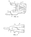
- the embodiment shown in FIGS. 15-22 also has an extension 116, but it is relatively flat and extends only approximately to the end of the grinding bit 16 as best shown in FIG. 17.
- the extension 116 is relatively flat and has a generally semicircular configuration 118 as shown from the top thereof.
- an attachment indicated generally at 150 which includes a body portion 152 having internal threads 154 and an opening 156 which is larger than the diameter of the grinding bit 16.
- the body portion 152 of this embodiment extends to a surface 158.
- a first jaw portion 160 is provided which has a support surface 162 with a predetermined acute angle relative to the access of the bit 16.
- a second jaw portion 164 is provided on the opposite side of the attachment 150 and it has a support surface 166 that is also at an acute angle relative to the grinding bit 16. As shown in the drawing, the angle of the support surface 162 is shown to be 30° while the angle of the support surface 166 is shown to be approximately 20°.
- the two support surfaces may have predetermined angles that are each within the range of about 15° to about 45°, it is desirable that the two support surfaces have different predetermined angles to enable a blade or tool to be sharpened with different angled cutting surfaces, if desired.
- This embodiment has an extension, indicated generally at 170, attached to said body portion and extending forwardly thereof and located between the first jaw portion 160 and the second jaw portion 164, with the extension 170 comprising side portions 172 located on opposite sides of the sharpening bit 16 and extending beyond the end of the sharpening bit and having a bridging portion 174 connecting said side portions 172 together.
- the bridging portion 174 has outer gap guide surfaces 176, 178 for contacting tool member (not shown).
- the gap guide surfaces 176, 178 preferably lie in respective planes that are at an acute angle relative to the axis of the sharpening bit, intercept the surface of the grinding bit 15 and are preferably parallel to the planes of the respective support surfaces 162 and 166.
- an improved sharpening attachment for a rotary hand tool that is effective and convenient in its use, and that it is extremely portable and yet is capable of sharpening tools, blades and the like in a manner that results in a constant sharpening angle.
- the design of the attachment enables it to be easily attached and removed without special tools and also contributes to its safety during use.
Landscapes
- Engineering & Computer Science (AREA)
- Mechanical Engineering (AREA)
- Finish Polishing, Edge Sharpening, And Grinding By Specific Grinding Devices (AREA)
- Grinding-Machine Dressing And Accessory Apparatuses (AREA)
Description
- The present invention relates to a removable sharpening attachment for use with a rotary hand tool according to the preamble of claim 1. Such a sharpening attachment is known from US 6,106,372. More particularly, the present invention relates to a removable sharpening attachment for a powered rotary hand tool that can be used to easily sharpen such items as gardening tools, metal blades and lawn mower blades.
- Various types of sharpening devices are currently known, including grinding wheels and discs that can coupled to a hand drill or other rotary hand tool. However, most sharpening devices that are used to sharpen tools, such as gardening tools, metal blades, lawn mower blades and the like, are devices that have support surfaces or guides for grinding a surface or an edge of a blade or tool at a particular angle. Devices of this type are most commonly relatively stationary rather than portable, in that the blade or tool is usually brought to the device for sharpening rather than the device being carried to the blade or tool where it is sharpened.
- U.S. Patent No. 6,106,372 discloses an electrode sharpener having a housing with multiple slots and openings for providing access to the grinding wheel completely enclosed into a cavity.
- The above mentioned problem is solved by a sharpening attachment according to claim 1. Further advantageous embodiments are disclosed in the dependent claims 2-21.
- In all of its embodiments, a sharpening attachment is provided which enables a user to sharpen the cutting edge of lawn mower blades, garden tools and the like in an easy and efficient manner, with the support surfaces presenting the member being sharpened at a desired angle so that the angle of the cutting edge is consistently ground along its length. The clean, compact design also greatly contributes to its efficient and easy use.
-
- FIGURE 1 is a perspective view from the side thereof of a first embodiment of the present invention shown mounted to a rotary hand tool and which also has a blade positioned within the attachment to be ground by a cylindrical grinding stone that is driven by the tool bit holder;
- FIG. 2 is a side elevation of the embodiment shown in FIG. 1;
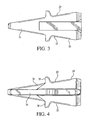
- FIG. 3 is a top view of the embodiment shown in FIG. 1;
- FIG. 4 is a bottom view of the embodiment shown in FIG. 1;
- FIG. 5 is a left end view of the embodiment shown in FIG. 1;
- FIG. 6 is a right end view of the embodiment shown in FIG. 1;
- FIG. 7 is a cross-section taken generally along the line 7-7 of FIG. 6;
- FIG. 8 is a cross-section taken generally along the line 8-8 of FIG. 5;
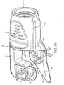
- FIG. 9 is a left side perspective view of a second embodiment of the present invention and shown attached to a rotary hand tool and illustrating a blade inserted in the attachment to be sharpened by a cylindrical grinding bit;
- FIG. 10 is a left side/bottom perspective view of the embodiment shown in FIG. 9;
- FIG. 11 is a right plan view of the attachment shown in FIG. 9;
- FIG. 12 is a top view of the attachment shown in FIG. 9;
- FIG. 13 is a bottom plan view of the attachment shown in FIG. 9;
- FIG. 14 is a right end view of the attachment shown in FIG. 9;
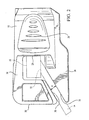
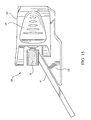
- FIG. 15 is a side plan view of a third embodiment not being part of the present invention and is shown attached to a rotary hand tool which has a grinding bit installed therein and with a blade in position for sharpening;
- FIG. 16 is a left plan view of the embodiment shown in FIG. 15;
- FIG. 17 is a top plan view of the embodiment shown in FIG. 15;
- FIG. 18 is a bottom plan view of the embodiment shown in FIG. 15;
- FIG. 19 is a right end view of the embodiment shown in FIG. 15;
- FIG. 20 is a left end view of the embodiment shown in FIG. 15;
- FIG. 21 is a cross section taken along the line 21-21 in FIG. 20;
- FIG. 22 is a cross section taken along the line 22-22 in FIG. 19;
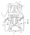
- FIG. 23 is a perspective view of a fourth embodiment of the present invention; and,
- FIG. 24 is a front elevation of the embodiment shown in FIG. 23.
- The sharpening attachment of the present invention can be used with a rotary tool of the type which utilizes a motor to rotate an output shaft having a collet holding a sharpening bit such as a grinding stone held for engaging a work surface of a tool. The hand tool may be a rotary hand tool such as those marketed under the Dremel brand made by the S-B Power Tool Company of Chicago, Illinois. The tool may also be an electric drill or other rotary tool, provided that the tool has a stationary mounting portion adjacent the collet so that the apparatus can be attached to the tool.
- It should also be understood that while each of the embodiments illustrated and described herein are mounted to the nose portion of a rotary hand tool using cooperative threaded portions on the attachment as well as on the nose portion of the rotary tool, it should be understood that other mechanisms for mounting the attachment to the rotary hand tool may be utilized, including such mechanisms as a bayonet-type attachment or press-fit cooperative mating surfaces.
- Turning now to the drawings, a first embodiment of the present invention is shown in FIGS. 1-8, with FIG. 1 particularly illustrating an attachment, indicated generally at 10, being mounted on the
nose portion 12 of a poweredrotary tool 12. Theattachment 10 has ablade 14 in position to be sharpened by a generally cylindrical shaped grinding or sharpeningbit 16 that is mounted to the rotary hand tool by a collet (not shown) that is mounted to an output shaft (not shown) of the rotary hand tool. The collet and output shaft are conventional and well known and thesharpening bit 16 also typically has a metal shaft that fits within the collet of the rotary hand tool. Theattachment 10 has abody portion 18 that is generally cylindrical but which has a pair of recessedflat portions 20 on opposite sides of thebody portion 18. As shown in FIG. 6, the right end of thebody portion 18 hasinternal threads 22 which engage external threads of the nose portion 12 (not shown), and the interior of thebody portion 18 has aninternal diameter 24 that is larger than the outside diameter of thegrinding bit 16. This is important in that it enables the attachment to be screwed on and off of the rotary tool with the grindingbit 16 being attached. It should be understood that the shaft of thegrinding bit 16 together with the length of the grinding portion of the bit should be dimensioned so that it is exposed beyond the end of thebody portion 18 as shown in FIG. 1. - The
attachment 10 has ajaw portion 26 that extends forwardly of the end (defined by the flat surface 28) of thebody portion 18 and the jaw portion has asupport surface 30. The angle of thesupport surface 30 is preferably predetermined and can be within the range of about 15° to about 45° relative to the axis of the sharpeningbit 16. The particular embodiment shown in FIG. 1-8 has a support surface that is at an acute angle of approximately 30° relative to the axis of thebit 16 which is horizontal in the drawing of FIG. 2, for example. The relationship between thesurface 30 and theblade member 14 that is being sharpened by thegrinding bit 16 is particularly well illustrated in FIG. 1. It is also important that theedge 32 of theblade 14 be in contact with the outer surface of thesharpening bit 16, and in that regard, the plane of thesupport surface 30 intersects the outer surface of thegrinding bit 16 as shown in phantom in FIG. 2, so that the entire thickness of the blade will be sharpened by thebit 16. - The
attachment 10 also includes anextension 34 that is attached to thebody portion 18 and extends forwardly along the top thereof. In this first embodiment, theextension 34 extends well beyond the end of thesharpening bit 16 and has atransverse end portion 36 that extends radially inwardly toward thebit 16 and beyond it to the other side thereof and terminates in agap guide surface 38. As best shown in FIG. 2, thegap guide surface 38 also lies in a plane which extends to the circumference of thegrinding bit 16 and is substantially parallel to the plane in which thesupport surface 30 lies. Since the distance D between thesurfaces - A second embodiment of the present invention is indicated generally at 50 in FIG. 9 and is shown attached to a
rotary hand tool 12 and is also shown with agrinding bit 16 attached to therotary hand tool 12 and with ablade 14 positioned in the attachment to be sharpened. This embodiment has many similarities to the embodiment shown in FIG. 1-8, but has the advantage of being adjustable so that the angle of anedge 32 of theblade 14 can be changed within a significant range. In the embodiment shown in FIGS. 9-14 abody portion 52 has externalrecessed flats 54 andinternal threads 56 for engaging the external threads of the nose portion of therotary tool 12. Thebody portion 52 has aninternal diameter 58 that is preferably larger than the outside diameter of thegrinding bit 16 so that theattachment 50 can be removed from therotary tool 12 with thegrinding bit 16 being in place. - The
attachment 50 has a jaw portion, indicated generally at 60, but is different than the first embodiment in that it has anadjustable jaw member 62 that is attached to astationary jaw extension 64 of thebody portion 52. Thejaw extension 64 has relativelythin parts 66 on opposite sides thereof, with a space between thepieces 66 sandwiching a comparablethin portion 68 of theadjustable jaw member 62. Apertures are provided in thepieces bolt 70 can pass with anut 72 being provided on the opposite side for securing the angular position of thejaw member 62. By loosening the nut, the angular position of the jaw member can be adjusted to provide the desired angle of asupport surface 74 relative to the grindingbit 16. - As with the first embodiment, the plane in which the
support surface 74 lies intersects the circumference of the grindingbit 16 to assure that theentire surface 32 of theblade 14 that is being sharpened is in contact with the grindingbit 16. The outer end of the body portion has a flat surface or end 76 and anextension 78 is provided which extends beyond the end of the grindingbit 16 as best shown in FIG. 11. The extension also has atransverse end portion 80 in which aslidable member 82 is located, with theslidable member 82 having anelongated slot 84. Themember 82 is movable in anopening 86 best shown in FIG. 12. Abolt 88 fits within an aperture in each side of thetransverse end portion 80 as well as theelongated slot 84 and anut 90 is provided on the opposite side thereof. By loosening thenut 90, theslidable member 82 can be moved vertically relative to thetransverse end portion 80 so that thebottom edge 92 can be adjusted relative to thesupport surface 74 to accommodate different thicknesses of blades or tools such as theblade 14. - Turning now to a third embodiment shown in FIGS. 15-22 but not being part of the present invention, and indicated generally at 100, it has a
body portion 102 with recessedflats 104, an interior threadedportion 106 with theopening 108 having an internal diameter that is greater than that of the grindingbit 16. Ajaw portion 110 is provided that is substantially similar to thejaw portion 26 of the first embodiment, it having asupport surface 112 that is fixed at a predetermined angle that is preferably within the range of about 15° to about 45°. The body portion extends to thesurface 114. The embodiment shown in FIGS. 15-22 also has anextension 116, but it is relatively flat and extends only approximately to the end of the grindingbit 16 as best shown in FIG. 17. Theextension 116 is relatively flat and has a generallysemicircular configuration 118 as shown from the top thereof. - Turning now to a fourth embodiment as shown in FIGS. 23 and 24, an attachment indicated generally at 150 is provided which includes a
body portion 152 havinginternal threads 154 and anopening 156 which is larger than the diameter of the grindingbit 16. Thebody portion 152 of this embodiment extends to asurface 158. Afirst jaw portion 160 is provided which has asupport surface 162 with a predetermined acute angle relative to the access of thebit 16. Asecond jaw portion 164 is provided on the opposite side of theattachment 150 and it has asupport surface 166 that is also at an acute angle relative to the grindingbit 16. As shown in the drawing, the angle of thesupport surface 162 is shown to be 30° while the angle of thesupport surface 166 is shown to be approximately 20°. It should be appreciated that the two support surfaces may have predetermined angles that are each within the range of about 15° to about 45°, it is desirable that the two support surfaces have different predetermined angles to enable a blade or tool to be sharpened with different angled cutting surfaces, if desired. - This embodiment has an extension, indicated generally at 170, attached to said body portion and extending forwardly thereof and located between the
first jaw portion 160 and thesecond jaw portion 164, with theextension 170 comprisingside portions 172 located on opposite sides of the sharpeningbit 16 and extending beyond the end of the sharpening bit and having a bridgingportion 174 connecting saidside portions 172 together. The bridgingportion 174 has outer gap guide surfaces 176, 178 for contacting tool member (not shown). The gap guide surfaces 176, 178 preferably lie in respective planes that are at an acute angle relative to the axis of the sharpening bit, intercept the surface of the grinding bit 15 and are preferably parallel to the planes of the respective support surfaces 162 and 166. - From the foregoing, it should be appreciated that an improved sharpening attachment for a rotary hand tool that is effective and convenient in its use, and that it is extremely portable and yet is capable of sharpening tools, blades and the like in a manner that results in a constant sharpening angle. The design of the attachment enables it to be easily attached and removed without special tools and also contributes to its safety during use.
- While various embodiments of the present invention have been shown and described, it should be understood that other modifications, substitutions and alternatives are apparent to one of ordinary skill in the art. Such modifications, substitutions and alternatives can be made without departing from the scope of the invention, as disclosed in the appended claims.
- Where technical features mentioned in any claim are followed by reference signs, those reference signs have been included for the sole purpose of increasing the intelligibility of the claims and accordingly, such reference signs do not have any limiting effect on the scope of each element identified by way of example by such reference signs.
Claims (21)
- A sharpening attachment (10) for a rotary hand tool (12) having an output shaft with a tool bit holder and a housing with a nose portion (12) including an opening in which the output shaft is located, and a sharpening bit (16) mounted in the tool bit holder for engaging a work surface, said attachment (10) comprising:a body portion (18) having a rear end for mounting to the housing of the hand tool (12), said body portion (18) having an internal opening aligned with the output shaft and sized to receive and permit rotation of the tool bit holder and a generally cylindrical sharpening bit (16), characterized in that at least a portion of the sharpening bit (16) is exposed forwardly of said rear end for engagement with a tool member such as gardening tools, metals blades, lawn mover blades and the like to be sharpened; and in that it further comprisesa jaw portion (26) attached to said body portion (18) and extending forwardly along one side thereof and having a support surface (30) for holding the tool member relative to the sharpening bit (16), said surface (30) lying in a plane at an acute angle relative to the sharpening bit; andan extension (34) attached to said body portion (18) and extending forwardly thereof to a point that is coextensive with at least a major portion of the exposed portion of the sharpening bit (16) to thereby define a protective guard, said extension (34) being on the side opposite said jaw portion (26), said extension (34) extending beyond the end of the sharpening bit (16) and having a transverse end portion (36) that extends to the opposite side thereof, said end portion (36) having a gap guide surface (38) for contacting the tool member.
- A sharpening attachment (10) as defined in claim 1 wherein said nose portion (12) has threads adapted to engage the attachment, the interior of said body portion (18) having an interior threads for engaging the nose threads.
- A sharpening attachment (10) as defined in claim 2 wherein said body portion (18) has generally flat surfaces (28) on opposite sides thereof for facilitating a user turning the body portion (18) to attach or remove said attachment.
- A sharpening attachment (10) as defined in claim 1 wherein said body portion (18), said jaw portion (26) and said extension (34) are integrally formed of a plastic or plastic-like material.
- A sharpening attachment (10) as defined in claim 1 wherein said internal opening of said body portion (18) being slightly larger than the sharpening bit (16) so that said attachment can be mounted on the rotary hand tool (12) while the sharpening bit (16) is attached in the tool bit holder.
- A sharpening attachment (10) as defined in claim 1 wherein said gap guide surface (38) is in a plane that is at an acute angle relative to the axis of the sharpening bit (16), with the plane also intersecting the outer circumference of the sharpening bit (16).
- A sharpening attachment (10) as defined in claim 6 wherein said plane of said gap guide surface (38) is substantially parallel to the plane of said support surface (30), the distance between said planes being predetermined and defining the maximum thickness of the tool member.
- A sharpening attachment (10) as defined in claim 1 wherein said jaw portion (26) is pivotally attached to said body portion (18) so that the support surface (30) lying in a plane that is at an adjustable acute angle relative to the axis of the sharpening bit (16) so that tool members can be sharpened to different angles by the sharpening bit (16).
- A sharpening attachment (10) as defined in claim 8 wherein said extension (34) extends beyond the end of the sharpening bit (16) and has a transverse end portion (36) that is adjustable in the radial direction toward the opposite side thereof, said end portion (36) having a gap guide surface (38) for contacting the tool member.
- A sharpening attachment (10) as defined in claim 9 wherein said gap guide surface (38) of said transverse end portion (36) can be moved relative to the plane of said support surface (30), the distance between said surface and said plane being adjustable to the thickness of the tool member.
- A sharpening attachment (10) as defined in claim 10 wherein said transverse end portion (36) is secured to said extension (34) by a nut and bolt, with the transverse end portion (36) having an elongated slot in which said bolt is located, the transverse end portion (36) being slidable relative to said bolt to vary the distance between gap guide surface (38) and said support surface (30).
- A sharpening attachment (10) as defined in claim 1 wherein said extension (34) is generally flat and terminates approximately at the outer end of the sharpening bit (16).
- A sharpening attachment (10) as defined in claim 12 wherein said extension (34) has a width that is wider than the sharpening bit (16) and has a generally semicircular end configuration.
- A sharpening attachment (10) as defined in claim 1 further comprising a second jaw portion (26) located generally on the side of said body portion (18) opposite said jaw portion (26), said second jaw portion (26) extending forwardly along one side thereof and having a second support surface (30) for holding the tool member relative to the sharpening bit (16).
- A sharpening attachment (10) as defined in claim 14 wherein the sharpening bit (16) is generally cylindrically shaped, said support surface (30) lying in a plane that is at an acute first predetermined angle relative to the axis of the sharpening bit (16), said plane intersecting the outer circumference of the sharpening bit (16), said second support surface (30) lying in a plane that is at an acute predetermined angle relative to the axis of the sharpening bit (16), said plane intersecting the outer circumference of the sharpening bit (16).
- A sharpening attachment (10) as defined in claim 15 wherein said first predetermined angle is different from said second predetermined angle.
- A sharpening attachment (10) as defined in claim 15 wherein said extension (34) is located between said jaw portion (26) and said second jaw portion (26) and comprises side portions located on opposite sides of the sharpening bit (16), said extension (34) extending beyond the end of the sharpening bit (16) and having a bridging portion connecting said side portions together, each of the outer surfaces of said bridging portion lying in respective planes that are at an acute angle relative to the axis of the sharpening bit (16).
- A sharpening attachment (10) as defined in claim 17 wherein the plane of each of said outer surfaces of said bridging portion intersects the outer circumference of the sharpening bit (16).
- A sharpening attachment (10) as defined in claim 1 wherein it further comprises a second jaw portion located generally on the side of said body portion (18) opposite said first jaw portion (26), said second jaw portion (26) extending forwardly along one side thereof and having a second support surface (30) for holding the tool member relative to the sharpening bit (16); and said extension (34) attached to said body portion (18) is located between said first jaw portion (26) and said second jaw portion (26), said extension (34) comprising side portions located on opposite sides of the sharpening bit (16), said extension (34) extending beyond the end of the sharpening bit (16) and having a bridging portion connecting said side portions together, each of the outer surfaces of said bridging portion lying in respective planes that are at an acute angle relative to the axis of the sharpening bit (16).
- A sharpening attachment (10) as defined in claim 19 wherein said first support surface (30) lies in a first plane that is at an acute first predetermined angle relative to the axis of the sharpening bit (16), said first plane intersecting the outer circumference of the sharpening bit (16), said second support surface (30) lying in a second plane that is at an acute predetermined angle relative to the axis of the sharpening bit (16), said second plane intersecting the outer circumference of the sharpening bit (16).
- A sharpening attachment (10) as defined in claim 19 wherein the plane of each of said outer surfaces of said bridging portion intersects the outer circumference of the sharpening bit (16).
Applications Claiming Priority (2)
| Application Number | Priority Date | Filing Date | Title |
|---|---|---|---|
| US10/062,031 US6846231B2 (en) | 2002-02-01 | 2002-02-01 | Removable sharpening attachment for a rotary hand tool |
| US62031 | 2002-02-01 |
Publications (3)
| Publication Number | Publication Date |
|---|---|
| EP1334800A2 EP1334800A2 (en) | 2003-08-13 |
| EP1334800A3 EP1334800A3 (en) | 2003-09-03 |
| EP1334800B1 true EP1334800B1 (en) | 2007-03-14 |
Family
ID=27610234
Family Applications (1)
| Application Number | Title | Priority Date | Filing Date |
|---|---|---|---|
| EP03001771A Expired - Lifetime EP1334800B1 (en) | 2002-02-01 | 2003-01-28 | Removable sharpening attachement for a rotary hand tool |
Country Status (3)
| Country | Link |
|---|---|
| US (1) | US6846231B2 (en) |
| EP (1) | EP1334800B1 (en) |
| DE (1) | DE60312418T2 (en) |
Families Citing this family (10)
| Publication number | Priority date | Publication date | Assignee | Title |
|---|---|---|---|---|
| US20050245175A1 (en) * | 2004-05-03 | 2005-11-03 | David Combs | In-situ blade sharpener |
| US20060040598A1 (en) * | 2004-08-20 | 2006-02-23 | Rudolf Koppe | Precision sharpener tool |
| US7507149B1 (en) * | 2007-03-06 | 2009-03-24 | Douglas Lawrence M | Drill bit dresser |
| DE102008019278A1 (en) | 2008-04-16 | 2009-10-22 | Marsch, Manuel | Adapter for e.g. electric drill comprises bracket containing drive shaft, tool shaft and gears, light channel around bracket containing e.g. optical fiber changing direction of illumination from that of drive shaft to that of tool shaft |
| GB2482332A (en) * | 2010-07-30 | 2012-02-01 | Elixair Internat Ltd | Automatic Portable Sharpening Apparatus with Tool Guide |
| WO2012159149A1 (en) * | 2011-05-23 | 2012-11-29 | Rosjoh Pty Ltd | Improvements in knife sharpening tools |
| US8616938B1 (en) * | 2011-06-29 | 2013-12-31 | Mark S. Mills | Hand-held blade sharpener |
| US8678882B1 (en) * | 2013-06-26 | 2014-03-25 | Edgecraft Corporation | Combination sharpener assembly |
| CN108296948A (en) * | 2017-01-13 | 2018-07-20 | 苏州宝时得电动工具有限公司 | Sander |
| CN113714868B (en) * | 2021-09-06 | 2024-10-11 | 四川简达金属构件有限公司 | A handheld electric knife sharpener |
Family Cites Families (15)
| Publication number | Priority date | Publication date | Assignee | Title |
|---|---|---|---|---|
| US2921416A (en) | 1960-01-19 | Lawn mower sharpener | ||
| US1664896A (en) * | 1925-09-16 | 1928-04-03 | George E Perdue | Grindstone attachment for sausage mills |
| US1961328A (en) | 1933-02-27 | 1934-06-05 | Dumore Company | Portable grinder for sharpening knives |
| US2114106A (en) | 1935-08-20 | 1938-04-12 | Geveke William | Grinding device |
| US2800755A (en) * | 1955-03-14 | 1957-07-30 | Joseph D Perra | Drill sharpener |
| US3139710A (en) * | 1963-06-04 | 1964-07-07 | S I Wener Dr | Sharpener for lawnmower blades |
| US3341981A (en) * | 1965-02-01 | 1967-09-19 | Louis J Baronyak | Twist drill bit sharpening device |
| US3812626A (en) | 1972-09-01 | 1974-05-28 | A Thompson | Ice skate sharpening device |
| CA1198896A (en) | 1984-08-09 | 1986-01-07 | Martin T. Carew | Portable skate sharpener |
| IE67176B1 (en) | 1991-02-15 | 1996-03-06 | Mayka Res & Dev | A Grinding Device |
| US5159784A (en) | 1991-08-12 | 1992-11-03 | Varner Sr James E | Portable apparatus for sharpening blades |
| US5951385A (en) | 1996-08-08 | 1999-09-14 | Credo Tool Company | Drill bit case and drill sharpener package |
| US5676591A (en) | 1996-08-13 | 1997-10-14 | Huang; Cheng-Hsien | Bit sharpener |
| US6106372A (en) | 1998-05-19 | 2000-08-22 | Clark; Roger T. | Tungsten electrode sharpener |
| US6257967B1 (en) * | 2000-03-08 | 2001-07-10 | Jim Schultz | Sharpener for veneer knife |
-
2002
- 2002-02-01 US US10/062,031 patent/US6846231B2/en not_active Expired - Lifetime
-
2003
- 2003-01-28 EP EP03001771A patent/EP1334800B1/en not_active Expired - Lifetime
- 2003-01-28 DE DE60312418T patent/DE60312418T2/en not_active Expired - Lifetime
Also Published As
| Publication number | Publication date |
|---|---|
| DE60312418T2 (en) | 2007-11-29 |
| DE60312418D1 (en) | 2007-04-26 |
| EP1334800A2 (en) | 2003-08-13 |
| US20030148720A1 (en) | 2003-08-07 |
| EP1334800A3 (en) | 2003-09-03 |
| US6846231B2 (en) | 2005-01-25 |
Similar Documents
| Publication | Publication Date | Title |
|---|---|---|
| US5163251A (en) | Hand-held knife sharpener | |
| US6464573B1 (en) | Guard attachment system with knurled clamp ring | |
| US9248562B2 (en) | Accessory attachment system for an oscillating power tool | |
| US4972589A (en) | Cutting and sanding attachments for a hand drill | |
| US9333612B2 (en) | Tool sharpener with adjustable support guide | |
| US8277292B2 (en) | Inline handheld power tool | |
| US4365397A (en) | File tool attachment | |
| US5371977A (en) | Portable, in-place sharpener for lawn mower blades and the like | |
| US6846231B2 (en) | Removable sharpening attachment for a rotary hand tool | |
| EP3275582B1 (en) | Miter saw | |
| US5062322A (en) | Universal lawn mower blade sharpening machine | |
| US6123611A (en) | Blade sharpening apparatus | |
| US7131205B2 (en) | Electric powered rotary saw | |
| US4532736A (en) | Sharpening device | |
| US6237656B1 (en) | Pencil sharpener bit | |
| US12172261B2 (en) | Blade sharpeners | |
| EP0161090B1 (en) | A grinding device | |
| EP1310335B1 (en) | Tool guard attachment for a rotary hand tool | |
| US5159784A (en) | Portable apparatus for sharpening blades | |
| US6044559A (en) | Cutting blade and stabilizing handle attachments for a power drill | |
| EP0396582B1 (en) | Hand-operated power tool | |
| US5024000A (en) | Material-removal woodworking tool | |
| US2921416A (en) | Lawn mower sharpener | |
| JP3516228B2 (en) | Cutting blade blade sharpening device | |
| JP3217679U (en) | Electric grinder, electric grinder with positioning tool |
Legal Events
| Date | Code | Title | Description |
|---|---|---|---|
| PUAI | Public reference made under article 153(3) epc to a published international application that has entered the european phase |
Free format text: ORIGINAL CODE: 0009012 |
|
| PUAL | Search report despatched |
Free format text: ORIGINAL CODE: 0009013 |
|
| AK | Designated contracting states |
Designated state(s): AT BE BG CH CY CZ DE DK EE ES FI FR GB GR HU IE IT LI LU MC NL PT SE SI SK TR |
|
| AX | Request for extension of the european patent |
Extension state: AL LT LV MK RO |
|
| AK | Designated contracting states |
Kind code of ref document: A3 Designated state(s): AT BE BG CH CY CZ DE DK EE ES FI FR GB GR HU IE IT LI LU MC NL PT SE SI SK TR |
|
| AX | Request for extension of the european patent |
Extension state: AL LT LV MK RO |
|
| RIC1 | Information provided on ipc code assigned before grant |
Ipc: 7B 24B 23/02 B Ipc: 7B 24B 3/36 A Ipc: 7B 25F 3/00 B |
|
| 17P | Request for examination filed |
Effective date: 20040205 |
|
| 17Q | First examination report despatched |
Effective date: 20040414 |
|
| AKX | Designation fees paid |
Designated state(s): DE FR GB IT |
|
| GRAP | Despatch of communication of intention to grant a patent |
Free format text: ORIGINAL CODE: EPIDOSNIGR1 |
|
| GRAS | Grant fee paid |
Free format text: ORIGINAL CODE: EPIDOSNIGR3 |
|
| GRAA | (expected) grant |
Free format text: ORIGINAL CODE: 0009210 |
|
| AK | Designated contracting states |
Kind code of ref document: B1 Designated state(s): DE FR GB IT |
|
| REG | Reference to a national code |
Ref country code: GB Ref legal event code: FG4D |
|
| REF | Corresponds to: |
Ref document number: 60312418 Country of ref document: DE Date of ref document: 20070426 Kind code of ref document: P |
|
| ET | Fr: translation filed | ||
| PLBE | No opposition filed within time limit |
Free format text: ORIGINAL CODE: 0009261 |
|
| STAA | Information on the status of an ep patent application or granted ep patent |
Free format text: STATUS: NO OPPOSITION FILED WITHIN TIME LIMIT |
|
| 26N | No opposition filed |
Effective date: 20071217 |
|
| PGFP | Annual fee paid to national office [announced via postgrant information from national office to epo] |
Ref country code: IT Payment date: 20090123 Year of fee payment: 7 |
|
| PGFP | Annual fee paid to national office [announced via postgrant information from national office to epo] |
Ref country code: FR Payment date: 20090120 Year of fee payment: 7 |
|
| REG | Reference to a national code |
Ref country code: FR Ref legal event code: ST Effective date: 20100930 |
|
| PG25 | Lapsed in a contracting state [announced via postgrant information from national office to epo] |
Ref country code: FR Free format text: LAPSE BECAUSE OF NON-PAYMENT OF DUE FEES Effective date: 20100201 |
|
| PG25 | Lapsed in a contracting state [announced via postgrant information from national office to epo] |
Ref country code: IT Free format text: LAPSE BECAUSE OF NON-PAYMENT OF DUE FEES Effective date: 20100128 |
|
| PGFP | Annual fee paid to national office [announced via postgrant information from national office to epo] |
Ref country code: GB Payment date: 20220125 Year of fee payment: 20 Ref country code: DE Payment date: 20220324 Year of fee payment: 20 |
|
| REG | Reference to a national code |
Ref country code: DE Ref legal event code: R071 Ref document number: 60312418 Country of ref document: DE |
|
| REG | Reference to a national code |
Ref country code: GB Ref legal event code: PE20 Expiry date: 20230127 |
|
| PG25 | Lapsed in a contracting state [announced via postgrant information from national office to epo] |
Ref country code: GB Free format text: LAPSE BECAUSE OF EXPIRATION OF PROTECTION Effective date: 20230127 |