EP1333681A2 - Filtering method and apparatus for reducing block artifacts or ringing noise - Google Patents
Filtering method and apparatus for reducing block artifacts or ringing noise Download PDFInfo
- Publication number
- EP1333681A2 EP1333681A2 EP03250529A EP03250529A EP1333681A2 EP 1333681 A2 EP1333681 A2 EP 1333681A2 EP 03250529 A EP03250529 A EP 03250529A EP 03250529 A EP03250529 A EP 03250529A EP 1333681 A2 EP1333681 A2 EP 1333681A2
- Authority
- EP
- European Patent Office
- Prior art keywords
- block
- filter information
- pixel
- filter
- values
- Prior art date
- Legal status (The legal status is an assumption and is not a legal conclusion. Google has not performed a legal analysis and makes no representation as to the accuracy of the status listed.)
- Ceased
Links
Images




Classifications
-
- H—ELECTRICITY
- H04—ELECTRIC COMMUNICATION TECHNIQUE
- H04N—PICTORIAL COMMUNICATION, e.g. TELEVISION
- H04N19/00—Methods or arrangements for coding, decoding, compressing or decompressing digital video signals
- H04N19/85—Methods or arrangements for coding, decoding, compressing or decompressing digital video signals using pre-processing or post-processing specially adapted for video compression
- H04N19/86—Methods or arrangements for coding, decoding, compressing or decompressing digital video signals using pre-processing or post-processing specially adapted for video compression involving reduction of coding artifacts, e.g. of blockiness
-
- G—PHYSICS
- G06—COMPUTING OR CALCULATING; COUNTING
- G06T—IMAGE DATA PROCESSING OR GENERATION, IN GENERAL
- G06T5/00—Image enhancement or restoration
- G06T5/50—Image enhancement or restoration using two or more images, e.g. averaging or subtraction
-
- G—PHYSICS
- G06—COMPUTING OR CALCULATING; COUNTING
- G06T—IMAGE DATA PROCESSING OR GENERATION, IN GENERAL
- G06T7/00—Image analysis
- G06T7/0002—Inspection of images, e.g. flaw detection
-
- H—ELECTRICITY
- H04—ELECTRIC COMMUNICATION TECHNIQUE
- H04N—PICTORIAL COMMUNICATION, e.g. TELEVISION
- H04N1/00—Scanning, transmission or reproduction of documents or the like, e.g. facsimile transmission; Details thereof
- H04N1/38—Circuits or arrangements for blanking or otherwise eliminating unwanted parts of pictures
-
- H—ELECTRICITY
- H04—ELECTRIC COMMUNICATION TECHNIQUE
- H04N—PICTORIAL COMMUNICATION, e.g. TELEVISION
- H04N19/00—Methods or arrangements for coding, decoding, compressing or decompressing digital video signals
-
- H—ELECTRICITY
- H04—ELECTRIC COMMUNICATION TECHNIQUE
- H04N—PICTORIAL COMMUNICATION, e.g. TELEVISION
- H04N19/00—Methods or arrangements for coding, decoding, compressing or decompressing digital video signals
- H04N19/10—Methods or arrangements for coding, decoding, compressing or decompressing digital video signals using adaptive coding
- H04N19/102—Methods or arrangements for coding, decoding, compressing or decompressing digital video signals using adaptive coding characterised by the element, parameter or selection affected or controlled by the adaptive coding
- H04N19/117—Filters, e.g. for pre-processing or post-processing
-
- H—ELECTRICITY
- H04—ELECTRIC COMMUNICATION TECHNIQUE
- H04N—PICTORIAL COMMUNICATION, e.g. TELEVISION
- H04N19/00—Methods or arrangements for coding, decoding, compressing or decompressing digital video signals
- H04N19/10—Methods or arrangements for coding, decoding, compressing or decompressing digital video signals using adaptive coding
- H04N19/102—Methods or arrangements for coding, decoding, compressing or decompressing digital video signals using adaptive coding characterised by the element, parameter or selection affected or controlled by the adaptive coding
- H04N19/124—Quantisation
-
- H—ELECTRICITY
- H04—ELECTRIC COMMUNICATION TECHNIQUE
- H04N—PICTORIAL COMMUNICATION, e.g. TELEVISION
- H04N19/00—Methods or arrangements for coding, decoding, compressing or decompressing digital video signals
- H04N19/10—Methods or arrangements for coding, decoding, compressing or decompressing digital video signals using adaptive coding
- H04N19/134—Methods or arrangements for coding, decoding, compressing or decompressing digital video signals using adaptive coding characterised by the element, parameter or criterion affecting or controlling the adaptive coding
- H04N19/136—Incoming video signal characteristics or properties
- H04N19/137—Motion inside a coding unit, e.g. average field, frame or block difference
-
- H—ELECTRICITY
- H04—ELECTRIC COMMUNICATION TECHNIQUE
- H04N—PICTORIAL COMMUNICATION, e.g. TELEVISION
- H04N19/00—Methods or arrangements for coding, decoding, compressing or decompressing digital video signals
- H04N19/10—Methods or arrangements for coding, decoding, compressing or decompressing digital video signals using adaptive coding
- H04N19/134—Methods or arrangements for coding, decoding, compressing or decompressing digital video signals using adaptive coding characterised by the element, parameter or criterion affecting or controlling the adaptive coding
- H04N19/136—Incoming video signal characteristics or properties
- H04N19/14—Coding unit complexity, e.g. amount of activity or edge presence estimation
-
- H—ELECTRICITY
- H04—ELECTRIC COMMUNICATION TECHNIQUE
- H04N—PICTORIAL COMMUNICATION, e.g. TELEVISION
- H04N19/00—Methods or arrangements for coding, decoding, compressing or decompressing digital video signals
- H04N19/10—Methods or arrangements for coding, decoding, compressing or decompressing digital video signals using adaptive coding
- H04N19/134—Methods or arrangements for coding, decoding, compressing or decompressing digital video signals using adaptive coding characterised by the element, parameter or criterion affecting or controlling the adaptive coding
- H04N19/164—Feedback from the receiver or from the transmission channel
-
- H—ELECTRICITY
- H04—ELECTRIC COMMUNICATION TECHNIQUE
- H04N—PICTORIAL COMMUNICATION, e.g. TELEVISION
- H04N19/00—Methods or arrangements for coding, decoding, compressing or decompressing digital video signals
- H04N19/10—Methods or arrangements for coding, decoding, compressing or decompressing digital video signals using adaptive coding
- H04N19/169—Methods or arrangements for coding, decoding, compressing or decompressing digital video signals using adaptive coding characterised by the coding unit, i.e. the structural portion or semantic portion of the video signal being the object or the subject of the adaptive coding
- H04N19/17—Methods or arrangements for coding, decoding, compressing or decompressing digital video signals using adaptive coding characterised by the coding unit, i.e. the structural portion or semantic portion of the video signal being the object or the subject of the adaptive coding the unit being an image region, e.g. an object
- H04N19/176—Methods or arrangements for coding, decoding, compressing or decompressing digital video signals using adaptive coding characterised by the coding unit, i.e. the structural portion or semantic portion of the video signal being the object or the subject of the adaptive coding the unit being an image region, e.g. an object the region being a block, e.g. a macroblock
-
- H—ELECTRICITY
- H04—ELECTRIC COMMUNICATION TECHNIQUE
- H04N—PICTORIAL COMMUNICATION, e.g. TELEVISION
- H04N19/00—Methods or arrangements for coding, decoding, compressing or decompressing digital video signals
- H04N19/10—Methods or arrangements for coding, decoding, compressing or decompressing digital video signals using adaptive coding
- H04N19/169—Methods or arrangements for coding, decoding, compressing or decompressing digital video signals using adaptive coding characterised by the coding unit, i.e. the structural portion or semantic portion of the video signal being the object or the subject of the adaptive coding
- H04N19/179—Methods or arrangements for coding, decoding, compressing or decompressing digital video signals using adaptive coding characterised by the coding unit, i.e. the structural portion or semantic portion of the video signal being the object or the subject of the adaptive coding the unit being a scene or a shot
-
- H—ELECTRICITY
- H04—ELECTRIC COMMUNICATION TECHNIQUE
- H04N—PICTORIAL COMMUNICATION, e.g. TELEVISION
- H04N19/00—Methods or arrangements for coding, decoding, compressing or decompressing digital video signals
- H04N19/10—Methods or arrangements for coding, decoding, compressing or decompressing digital video signals using adaptive coding
- H04N19/169—Methods or arrangements for coding, decoding, compressing or decompressing digital video signals using adaptive coding characterised by the coding unit, i.e. the structural portion or semantic portion of the video signal being the object or the subject of the adaptive coding
- H04N19/18—Methods or arrangements for coding, decoding, compressing or decompressing digital video signals using adaptive coding characterised by the coding unit, i.e. the structural portion or semantic portion of the video signal being the object or the subject of the adaptive coding the unit being a set of transform coefficients
-
- H—ELECTRICITY
- H04—ELECTRIC COMMUNICATION TECHNIQUE
- H04N—PICTORIAL COMMUNICATION, e.g. TELEVISION
- H04N19/00—Methods or arrangements for coding, decoding, compressing or decompressing digital video signals
- H04N19/60—Methods or arrangements for coding, decoding, compressing or decompressing digital video signals using transform coding
-
- H—ELECTRICITY
- H04—ELECTRIC COMMUNICATION TECHNIQUE
- H04N—PICTORIAL COMMUNICATION, e.g. TELEVISION
- H04N19/00—Methods or arrangements for coding, decoding, compressing or decompressing digital video signals
- H04N19/60—Methods or arrangements for coding, decoding, compressing or decompressing digital video signals using transform coding
- H04N19/61—Methods or arrangements for coding, decoding, compressing or decompressing digital video signals using transform coding in combination with predictive coding
-
- H—ELECTRICITY
- H04—ELECTRIC COMMUNICATION TECHNIQUE
- H04N—PICTORIAL COMMUNICATION, e.g. TELEVISION
- H04N19/00—Methods or arrangements for coding, decoding, compressing or decompressing digital video signals
- H04N19/60—Methods or arrangements for coding, decoding, compressing or decompressing digital video signals using transform coding
- H04N19/625—Methods or arrangements for coding, decoding, compressing or decompressing digital video signals using transform coding using discrete cosine transform [DCT]
-
- H—ELECTRICITY
- H04—ELECTRIC COMMUNICATION TECHNIQUE
- H04N—PICTORIAL COMMUNICATION, e.g. TELEVISION
- H04N19/00—Methods or arrangements for coding, decoding, compressing or decompressing digital video signals
- H04N19/80—Details of filtering operations specially adapted for video compression, e.g. for pixel interpolation
-
- H—ELECTRICITY
- H04—ELECTRIC COMMUNICATION TECHNIQUE
- H04N—PICTORIAL COMMUNICATION, e.g. TELEVISION
- H04N19/00—Methods or arrangements for coding, decoding, compressing or decompressing digital video signals
- H04N19/80—Details of filtering operations specially adapted for video compression, e.g. for pixel interpolation
- H04N19/82—Details of filtering operations specially adapted for video compression, e.g. for pixel interpolation involving filtering within a prediction loop
-
- H—ELECTRICITY
- H04—ELECTRIC COMMUNICATION TECHNIQUE
- H04N—PICTORIAL COMMUNICATION, e.g. TELEVISION
- H04N19/00—Methods or arrangements for coding, decoding, compressing or decompressing digital video signals
- H04N19/85—Methods or arrangements for coding, decoding, compressing or decompressing digital video signals using pre-processing or post-processing specially adapted for video compression
- H04N19/89—Methods or arrangements for coding, decoding, compressing or decompressing digital video signals using pre-processing or post-processing specially adapted for video compression involving methods or arrangements for detection of transmission errors at the decoder
- H04N19/895—Methods or arrangements for coding, decoding, compressing or decompressing digital video signals using pre-processing or post-processing specially adapted for video compression involving methods or arrangements for detection of transmission errors at the decoder in combination with error concealment
-
- H—ELECTRICITY
- H04—ELECTRIC COMMUNICATION TECHNIQUE
- H04N—PICTORIAL COMMUNICATION, e.g. TELEVISION
- H04N5/00—Details of television systems
- H04N5/14—Picture signal circuitry for video frequency region
- H04N5/21—Circuitry for suppressing or minimising disturbance, e.g. moiré or halo
- H04N5/213—Circuitry for suppressing or minimising impulsive noise
Definitions
- the present invention relates to removing blocking artifacts and ringing noise, and more particularly, to a filtering method and apparatus for removing blocking artifacts and ringing noise caused when processing an image frame on a block-by-block basis.
- video data is encoded by processing image frames in block units.
- video data encoding standards such as moving picture experts group (MPEG) and H.263
- video data is encoded by performing a discrete cosine transform (DCT) and quantization on image frames in block units.
- DCT discrete cosine transform
- encoding image frames in block units may result in blocking artifacts and ringing noise.
- Blocking artifacts make an edge region, which was not contained in the original frame, occur in a reproduced image frame, thereby causing discontinuity between adjacent pixels of the edge region in the reproduced image frame.
- ringing noise occurs in an image frame, a borderline of an object in the image frame is not smoothly depicted, e.g., the borderline may be irregular. The higher a compression rate of the reproduced image frame, the more serious the blocking artifacts and the ringing noise.
- detection of an edge region of a pixel block reproduced due to the blocking artifacts and/or ringing noise is required to accomplish a conventional filtering method for removing blocking artifacts and/or ringing noise.
- the distribution of pixel values such as brightness, luminance, and color of pixels present on boundaries between the 8 ⁇ 8 or 4 ⁇ 4 pixel blocks are measured and the measured values are compared with a predetermined critical value.
- the critical value is experimentally obtained by measuring the distribution of the above pixel values, such as brightness, luminance, and color of pixels, finding a relationship between the distributions of the above pixel values, and determining whether the edge region is present or not in an image frame.
- pixel values in a boundary region between adjacent blocks must be checked in vertical or horizontal direction.
- the checking of every pixel value in the boundary region is almost impossible because of a large amount of calculation and complexity.
- pixel values are stored in a memory device in the vertical direction in chronological order, continuous access to the memory device is required to calculate pixel values in the vertical direction.
- continuous access to a memory device is, at least for the time being, highly impractical.
- An aim of the present invention is to provide a method and apparatus for efficiently removing blocking artifacts and/or ringing noise.
- a preferred aim is to provide such a method and apparatus which reduces processing cost and/or reduces memory access.
- the present invention provides a filtering method and apparatus for effectively detecting an edge region present in a pixel block.
- the present invention also provides a filtering method and apparatus for effectively detecting an edge region present in a pixel block with a small amount of calculation.
- a filtering method for removing blocking artifacts including (a) transforming video data in a block-by-block basis; and (b) detecting the presence of an edge region in the video data by checking the distribution of values obtained by the transformation.
- a filtering method for removing blocking artifacts including (a) transforming and quantizing video data in a block-by-block basis; (b) creating filter information based on the distribution of values obtained by the transformation and quantization; and (c) filtering the video data based on the filter information.
- (a) includes (a1) performing DCT the video data in a block-by-block basis to obtain DCT coefficients; and (a2) quantizing the DCT coefficients. More preferably, (a) includes performing DCT and quantization on a 4 ⁇ 4 pixel block to obtain a 4 ⁇ 4 quantized DCT block.
- (b) includes creating filter information indicating the degree of the occurrence of blocking artifacts and/or ringing noise based on the quantized DCT coefficients. More preferably, (b) comprises (b1) creating filter information by checking the values of pixels, except for a DC component, at the uppermost row of the quantized DCT block, where the filter information indicates whether an edge region is present in a vertical direction of the original pixel block.
- (b) also comprises (b2) creating filter information by checking the values of pixels, except for the DC component, at the leftmost column of the quantized DCT block, where the filter information indicates whether an edge region is present in a horizontal direction of the original pixel block.
- (b) may comprise (b3) creating filter information by checking the values of pixels not at the uppermost row and leftmost column of the quantized DCT block, where the filter information indicates whether an edge region is present in a diagonal direction of the original pixel block.
- (b) comprises setting a vertical blocking flag (VBF) and a horizontal blocking flag (HBF) to 1 as the filter information when only the pixel A has a value other than 0.
- (c) comprises deblocking filtering more strongly in the vertical and horizontal directions of the pixel block if the HBF and VBF are set to 1.
- (b) comprises setting the VBF to 1 as the filter information when only the pixels A and B have values other than 0, and (c) comprises deblocking filtering more strongly in the vertical direction of the pixel block when the VBF is set to 1.
- (b) comprises setting the HBF to 1 as the filter information when only the pixels A and C have values other than 0, and (c) comprises deblocking filtering more strongly in the horizontal direction of the pixel block when the HBF is set to 1.
- a ringing flag is set to 1 when the pixels A, B, and C have values other than 0, and (c) comprises deringing filtering more strongly when the RF is set to 1.
- a filtering method for removing blocking artifacts including (a) transforming and quantizing a block consisting of video data in pixel units so as to obtain quantized values, checking the obtained quantized values, and creating filter information when the checking result is for filter information; and (b) performing filtering based on the created filter information.
- (a) comprises (a1) performing DCT and quantization on one of pixels, except for a pixel corresponding to a DC component, at the uppermost and leftmost columns of the block to obtain a quantized DCT coefficient; and (a2) checking the quantized DCT coefficient, creating filter information based on the checking result when the quantized DCT coefficient is a value other than 0, and terminating performing DCT and quantization on the pixels at the uppermost row and leftmost column.
- (a) comprises (a3) checking the quantized DCT coefficient, and performing DCT and quantization on one of pixels, except for the pixel corresponding to the DC component, at the uppermost row and leftmost column when the quantized DCT coefficient is 0; (a4) repeatedly performing (a2) and (a3) on the remaining pixels, except for the pixel corresponding to the DC component and the one pixel, at the uppermost and leftmost columns so as to obtain quantized DCT coefficients; and (a5) creating filter information when the quantized DCT coefficients for all of the pixels at the uppermost row and leftmost column are 0.
- an encoder for encoding video data comprising a loop filter wherein the loop filter comprises: a filter information producing unit which creates filter information based on the distribution of values obtained by transforming and quantizing a pixel block; a filter characteristics decision unit which determines filter characteristics based on the created filter information; and a deblocking filter which deblocking filters based on the determined filter characteristics.
- the loop filter further comprises a loop transforming unit which transforms pixel values for inter frame in a block-by-block basis, and a loop quantizing unit which quantizes values transformed by the loop transforming unit.
- video data consists of a plurality of image frames.
- Image frames are encoded into an intra frame and an inter frame and then transmitted.
- the intra frame is encoded with no reference to other images and can be independently decoded.
- the inter frame is encoded based on a previous or next image, that is, a difference between the inter frame and the frame of a previous or next frame, and therefore, decoding of the inter frame requires the previous or next frame.
- Each image frame consists of a plurality of macro blocks, and each macro block contains a plurality of pixel blocks.
- an edge region is detected by transforming a macro block or a pixel block and checking the distribution of obtained transform values and/or values obtained by quantizing the transform values.
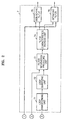
- Figure 1 is a block diagram of an encoding apparatus according to a preferred embodiment of the present invention.
- the encoding apparatus includes a motion estimator 1, a transformer 2, a quantizer 3, an inverse quantizer 4, an inverse transformer 5, a motion compensator 6, and a loop filter 7.
- the encoding apparatus further includes a controller (not shown), a first switch 10, a second switch 20, and a third switch 30, all switches being controlled by the controller.
- the controller controls the first switch 10 such that an intra frame and an inter frame are input directly to the transformer 2 and the motion estimator 1, respectively.
- the motion estimator 1 compares a pixel value with a previous pixel value in pixel block units and outputs a difference, i.e., motion vector, between the pixel value and the previous pixel value, to the transformer 2.
- the transformer 2 changes descriptive manner of data, i.e., transforms, for pixel values present in an image frame in case of the intra frame, and the difference, i.e., motion vector, in case of the inter frame.
- discrete cosine transform is performed to transform image frames but any applicable method such as a discrete wavelet transform (DWT) may be used instead of the DCT.
- the quantizer 3 quantizes the transformed values, i.e., DCT coefficients, according to predetermined quantization step.
- the quantization step may be determined adaptively to the respective block unit. However, the larger the size of the quantization step, the more noise due to quantization of values increases.
- Values, which are obtained by performing the DCT and quantization on an image frame are coded using variable-length coding (VLC), for example, and transmitted to a receiving end.
- VLC variable-length coding
- the values, which are obtained by the DCT and quantization are input to the inverse quantizer 4 or the loop filter 7.
- the controller controls the second switch 20 to input intra frames to the loop filter 7 and inter frames only to the inverse quantizer 4. More specifically, in case of intra frames, values output from the quantizer 3 are required to detect an edge region, that is, values obtained by performing the DCT and quantization on pixels in block units. Therefore, the values can be input directly to the loop filter 7 without being additionally processed. In case of inter frames, values output from the quantizer 3 are obtained by performing the DCT and quantization on differences (motion vectors) between the inter frames and their previous frames. Thus, the values are input to the inverse quantizer 4 to perform the DCT and quantization on pixels on a block-by-block basis, which is a process of restoring pixel values in block units.
- the inverse quantizer 4 inversely quantizes the given pixel values according to a predetermined quantization step, and the inverse transformer 5 inversely transforms the inversely quantized values. More specifically, in this embodiment, the inverse transformer 5 performs inverse discrete cosine transform (IDCT) on the inversely quantized values.
- IDCT inverse discrete cosine transform
- the inverse transformer 5 performs the inverse transform based on the transform method, instead of the IDCT. For instance, if the transformer 2 is set to perform discrete wavelet transform (DWT) on pixel values, the inverse transformer 5 performs inverse DWT (IDWT) thereon.
- DWT discrete wavelet transform
- IDWT inverse DWT
- Intra frames output from the inverse transformer 5 are pixel values to be filtered, i.e., pixel values of a current image frame, and thus are input to the loop filter 7. Inter frames need to be compensated for their motion to obtain pixel values for the current image frame, and thus are input to the motion compensator 6.
- the controller controls the third switch 30 to input the intra frames output from the inverse transformer 5 to the loop filter 7 and input the inter frames output from the inverse transformer 5 to the motion compensator 6.
- the motion compensator 6 adds differences between the inter frames and a previous image frame to the previous image frame in block units, restores the current image frame, and outputs the result to the loop filter 7.
- the loop filter 7 filters image frames.
- the loop filter 7 checks the distribution of values obtained by performing DCT and quantization thereon to determine whether an edge region is present in an image frame, and filters the image frame according to the checking result.
- the loop filter 7 checks values obtained by performing DCT and quantization on pixel values at the leftmost row and uppermost columns, respectively, so as to determines whether an edge region is present in an image frame. Next, the loop filter filters the image frame according to the checking result. A detailed description of the operations of the loop filter 7 will be described later.
- FIG. 2 is a block diagram of the loop filter 7 according to the first embodiment of the present invention.
- the loop filter 7 includes a loop transforming unit 71, a loop quantizing unit 72, a filter information producing unit 73, a filter characteristics decision unit 74, a deblocking filter 75, and a deringing filter 76.
- the object data 1 ⁇ refers to pixel values of image frames in block units.
- the object data 1 ⁇ of an intra frame is transmitted to the loop filter 7 via the third switch 30, and that of an inter frame is input from the motion compensator 6 to the loop filter 7.
- the filter information extraction data 2 ⁇ and 3 ⁇ refer to values obtained by performing DCT and quantization on pixel values of a certain block.
- the filter information extraction data 2 ⁇ of an intra frame refers to values obtained by performing DCT and quantization on pixel values on a certain block and is transmitted directly to the loop filter 7 via the second switch 20 so as to create filter information without an additional calculation process.
- the filter information extraction data 3 ⁇ of an inter frame is input to the loop filter 7 from the motion compensator 6 and thus must be transformed and quantized within the loop filter 7. For this reason, values input via the second switch 20, i.e., the filter information extraction data 2 ⁇ of an intra frame, are input to the filter information producing unit 73, and the values input from the motion compensator 6, i.e., the filter information extraction data 3 ⁇ of an inter frame, are input to the loop transforming unit 71.
- the loop transforming unit 71 and the loop quantizing unit 72 transforms and quantizes pixel values in a block-by-block basis for an inter frame, respectively.
- the loop transforming unit 71 and the loop quantizing unit 72 have the same functions, i.e., transformation and quantization, as the transformer 2 and the quantizer 3 shown in Figure 1.
- the transformation and quantization of the loop transforming unit 71 and the loop quantizing unit 72 do not need the same precision as the transformer 2 and the quantizer 3. This is because values produced by the loop transforming unit 71 and the loop quantizing unit 72 are used to only detect the occurrence of an edge region, and thus may have lower precision than those obtained by the transformer 2 and the quantizer 3 to encode video data.
- the loop transforming unit 71 and the loop quantizing unit 72 may lower precision in DCT and quantization by using integral operation instead of decimal operation, increasing the size of quantization step, or performing a fast-mode DCT, thereby reducing the amount of calculation.
- the quantized value is set to 1 if K ⁇ (2 20 -f ⁇ 2 20 ) / A(QP) , and is set to another predetermined value otherwise.
- the filtering information producing unit 73 creates filter information with values obtained by performing DCT and quantization on pixel values in a block-by-block basis. A detailed description of the operation of the filtering information producing unit 73 will be later described.
- the filter characteristics decision unit 74 determines and outputs filter characteristics based on the filter information.
- the deblocking filter 75 and the deranging filter 76 perform filtering on video data according to the determined filter characteristics.
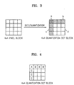
- FIGs 3 and 4 are diagrams illustrating a method for creating filter information using the filter information producing unit 3 of Figure 1, according to a first embodiment of the present invention.
- DCT and quantization are performed a 4 ⁇ 4 pixel block, which is a basic unit in the first embodiment, to obtain a 4 ⁇ 4 quantized DCT block (hereinafter, 'DCT block').
- a denotes a DC component
- b denotes pixels, except for the DC component a, at the uppermost row of the DCT block that indicate whether an edge region is present in the vertical direction of the DCT block
- c denotes pixels, except for the DC component a, at the leftmost column of the DCT block that indicate whether an edge region is present in the horizontal direction of the DCT block
- d denotes pixels, except for the values a through c at the leftmost and uppermost rows of the DCT block, which indicate the occurrence of ringing noise in a diagonal direction of the DCT block.
- filter information is created using the values of pixels A through C, according to a preferred embodiment of the present invention, shown in Figure 4.
- the presence or degree of blocking artifacts is determined by checking the values of the pixels A, B, and C and filter information is created according to the checking result, as follows:
- the filter characteristics decision unit 74 determines filter characteristics based on these flags. In other words, if the HBF is determined, the deblocking filter 75 is set to perform filtering more strongly in the horizontal direction of a pixel block. If the VBF is determined, the deblocking filter 75 is set to perform filtering more strongly in the vertical direction of the pixel block. If the RF is set, the deranging filter 76 is set to more strongly perform filtering the pixel block. Accordingly, it is possible to perform adaptive filtering on video data according to the degree of blocking artifacts and/or ringing noise.
- filter information is created using the values of the pixels A, B, and C to remove blocking artifacts.
- FIG 5 is a diagram illustrating filter information produced according to a modified example of the first embodiment of the present invention.
- a loop filter 7 of Figure 2 is used.
- the modified example of the first embodiment is different from the first embodiment in that discrete wavelet transform (DWT), instead of DCT, is performed on image frames.
- DWT discrete wavelet transform
- DWT and quantization are performed on a 4 ⁇ 4 pixel block to obtain four 2 ⁇ 2 quantized DWT blocks e through h.
- the block e is obtained by passing the 4 ⁇ 4 DCT block, of Figure 4, through a lowpass filter and corresponds to the DC component, i.e., pixel A , of the 4 ⁇ 4 quantized DCT block.
- the block f corresponds to the pixel B of the 4 ⁇ 4 quantized DCT block, i.e., it indicates whether an edge region is present in a horizontal direction of the original pixel block.
- the block g corresponds to the pixel C of the 4 ⁇ 4 quantized DCT block, i.e., it indicates whether an edge region is present in a vertical direction of the original pixel block.
- the block h corresponds to the other pixels, not on the uppermost and leftmost columns of the block to which the pixels A and B, and pixels A and C belong, of the 4 ⁇ 4 quantized DCT block.
- the block h indicates whether ringing noise occurs in the original pixel block.
- filter information is created using the values of the pixels A, B, and C.
- filter information indicating the occurrence of blocking artifacts and/or ringing noise is also created using the blocks e, f, g, and h.
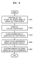
- FIG. 6 is a flow chart illustrating a filtering method according to a first embodiment of the present invention.
- an encoder performs DCT on input video data in a block-by-block basis in step 601 to obtain DCT coefficients.
- the DCT coefficients are quantized according to a predetermined quantization step to obtain a quantized DCT block in step 602.
- the encoder checks the distribution of values of pixels of the quantized DCT block in step 603, and creates filter information based on the checking result in step 604. With the filter information, it is possible to detect the degree of blocking artifacts and/or ringing noise.
- the encoder determines filter characteristics based on the created filter information and performs adaptive filtering on the input video data in step 605.
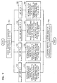
- FIG. 7 is a flow chart illustrating another filtering method according to the first embodiment of the present invention.
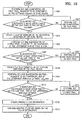
- the filter information producing unit 73 checks the distribution of values of pixels of a quantized DCT block, and sets a horizontal blocking flag HBF, a vertical blocking flag VBF, or a ringing flag RF to 1 or 0. If the HBF is set to 1 in step 702, the filter characteristics decision unit 74 determines filter characteristics such that the deblocking filter 75 performs filtering more strongly in the vertical direction of the DCT block, in step 703.
- the filter characteristics decision unit 74 determines and outputs filter characteristics such that the deblocking filter 75 performs filtering more strongly in the horizontal direction of the DCT block, in step 705. If the HBF and the VBF are set to 1 in step 706, the filter characteristics decision unit 74 determines filter characteristics such that the deblocking filter 75 performs filtering more strongly in the vertical and horizontal directions of the DCT block, in step 707. If the RF is set to 1 in step 708, the filter characteristics decision unit 74 determines filter characteristics such that the deranging filter 76 performs filtering more strongly on the DCT block, in step 709. Thereafter, the deblocking filter 75 and the deranging filter 76 perform adaptive filtering on input video data according to the set filter characteristics, in step 710.
- Deblocking filtering is performed in a block-by-block basis, but video data is in fact input to the encoder together with pixel values at border regions of blocks adjacent to a current block as well as the current block.
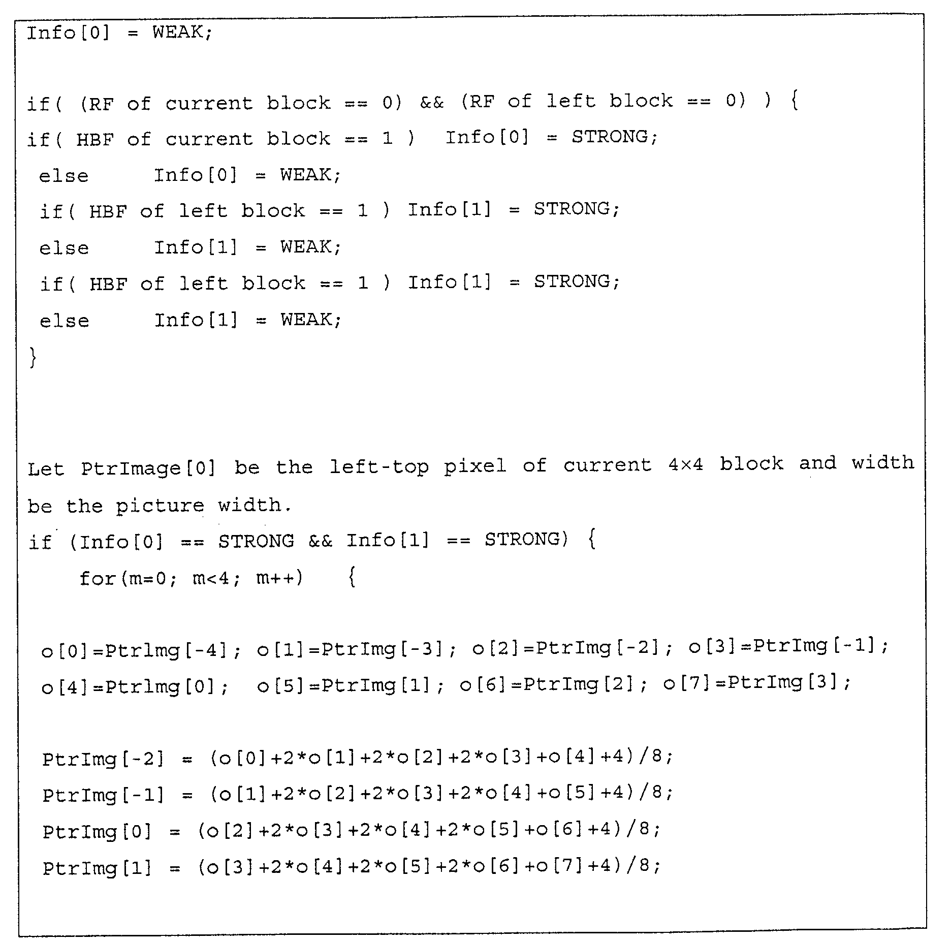
- the input pixel values are filtered by the deblocking filter 75 and outputs as changed values. For instance, adjacent values 3 through 6 are changed when pixel values 1 through 4 of the current block and pixel values 5 through 8 of the adjacent block are more strongly filtered by the deblocking filter 75, and only the values 4 and 5 are changed otherwise. Accordingly, a flag of an adjacent block is compared with that of a current block to adjust the characteristics value of the deblocking filter 75. That is, the filter characteristics value of the deblocking filter 75 is set to a strong value if the flag of the adjacent block is the same as that of the current block and set to a weak value otherwise.
- the filter information producing unit 73 may compare the flags VBF, HBF, and RF of the adjacent blocks with the flags VBF, HBF, and RF of the current block, and create filter information based on the comparison result.
- the created filter information can be more accurately expressed than the filter information created using flags of the current block, and thus, filter characteristics values can be more precisely determined.
- FIG 8 is a block diagram of the loop filter 2 according the second embodiment of the present invention.
- the loop filter 7 includes a loop transforming unit 81, a loop quantizing unit 82, a filter information producing unit 83, a filter characteristics decision unit 74, a deblocking filter 75, and a deranging filter 76.
- the object data 1 ⁇ refers to pixel values of image frames in block units.
- the object data 1 ⁇ of an intra frame is transmitted to the loop filter 7 via the third switch 30, and that of an inter frame is input from the motion compensator 6 to the loop filter 7.
- the filter information extraction data 2 ⁇ and 3 ⁇ refer to values obtained by performing DCT and quantization on pixel values of a certain block.
- the filter information extraction data 2 ⁇ of an intra frame refers to values obtained by performing DCT and quantization on pixel values on a certain block and is transmitted directly to the loop filter 7 via the second switch 20 so as to create filter information without an additional calculation process.
- the filter information extraction data 3 ⁇ of an inter frame is input to the loop filter 7 from the motion compensator 6 and thus must be transformed and quantized within the loop filter 7. For this reason, values input via the second switch 20, i.e., the filter information extraction data 2 ⁇ of an intra frame, are input to the filter information producing unit 83, and the values input from the motion compensator 6, i.e., the filter information extraction data 3 ⁇ of an inter frame, are input to the loop transforming unit 71.
- the loop transforming unit 81 performs DCT or DWT on first and second pixels at the leftmost row and uppermost column of a predetermined sized block of an input inter frame, respectively. In this case, DCT or DWT is performed on the first and second pixels of the leftmost column downward, and performed on the first and second pixels of the uppermost row from the left to the right.
- the loop quantizing unit 82 quantizes DCT coefficients transformed by the loop transforming unit 81.
- the DCT and quantization of the loop transforming unit 81 and the loop quantizing unit 82 are the same as the transformer 2 and the quantizer 3 described with reference to Figure 1. However, the transformation and quantization of the loop transforming unit 81 and the loop quantizing unit 82 do not need the same precision as the transformer 2 and the quantizer 3.
- the loop transforming unit 81 and the loop quantizing unit 82 may lower precision in DCT and quantization by using integral operation instead of decimal operation, increasing the size of quantization step, or performing a fast-mode DCT, thereby reducing the amount of calculation.
- the quantized value is set to 1 if K ⁇ (2 20 -f ⁇ 2 20 ) / A(QP) , and is set to another predetermined value otherwise.
- the filter information producing unit 83 checks if the first and second pixels at the leftmost and uppermost rows, on which DCT (or DWT) and quantization are performed, have values other than 0. If the DCT (or DWT) or quantized second pixel value at the leftmost or uppermost row is 0, the filter information producing unit 83 instructs the loop transforming unit 81 and the loop quantizing unit 82 to perform DCT (or DWT) on and quantize a next pixel. The filter information producing unit 83 receives a value of the next pixel and checks if the value is 0 and repeats the aforementioned operation.
- the filter information producing unit 83 creates filter information based on the result.
- a method for creating filter information is as described in the first embodiment.
- the filter information producing unit 83 instructs the loop transforming unit 81 and the loop quantizing unit 82 to stop performing DCT (or DWT) and quantizing a pixel value, respectively.
- DCT or DWT
- quantization of pixel values at the leftmost or uppermost row are terminated (a detailed description thereof will be later described).
- the filter characteristics decision unit 74 determines and outputs filter characteristics based on the filter information.
- the deblocking filter 75 and the deranging filter 76 perform filtering according to the determined filter characteristics.
- the operations of the filter characteristics decision unit 74, the deblocking filter 75, and the deranging filter 76 are the same as those of the filter characteristics decision unit 74, the deblocking filter 75, and the deranging filter 76 according to the first embodiment. Therefore, their descriptions will be omitted here.
- FIG. 9 is a diagram illustrating a method for obtaining filter information extraction data using the filter information producing unit 83 of Figure 8 and creating filter information from the filter information extraction data, according to the second embodiment of the present invention.
- DCT and quantization are performed on a first pixel C, which is indicated with oblique lines in (a), adjacent to a DC component A at the leftmost column of a 4 ⁇ 4 pixel block which is a basic unit for filtering in the present invention.
- it is checked a value obtained by DCT and quantization. If the value is other than 0, DCT and quantization are terminated and filter information is created based on the checking result.
- DCT and quantization are performed on a second pixel C, which is indicated with oblique lines in (b), to obtain other values. If the other value is other than 0, DCT and quantization are terminated and filter information is created on the checking result. However, if the other value is 0, DCT and quantization are performed on a third pixel C, which is indicated with oblique lines in (c), and then, it is also checked a still other value obtained by DCT and quantization. Likewise, if the still other value is other than 0, DCT and quantization are terminated and filter information is created based on the checking result. If the still other value is 0 and there is no pixel at the leftmost column, filter information is created based on the results already obtained. Filter information is obtained as described in the method according to the first embodiment of the present invention.
- DCT and quantization are performed on a first pixel B, adjacent to the DC component A, at the uppermost row of the 4 ⁇ 4 pixel block, indicated with oblique lines in (d).
- a value obtained by DCT and quantization If the value is other than 0, DCT and quantization are terminated and filter information is created based on the checking result.
- DCT and quantization are performed on a second pixel B, which is indicated with oblique lines in (e), and then, it is checked other value obtained by DCT and quantization. If the other value is other than 0, DCT and quantization are terminated and filter information is created on the checking result.
- DCT and quantization are performed on a third pixel, which is indicated with oblique lines in (f), and it is checked a still other value. If the still other value is other than 0, DCT and quantization are terminated and filter information is created on the checking result. However, if the still another value is 0 and there is no pixel at the uppermost row, filter information is created based on the results already obtained. Filter information is created as described in the method according to the first embodiment of the present invention.
- DCT and quantization are performed on pixels other than A, B, and C of the 4 ⁇ 4 pixel block in a block-by-block basis.
- a value obtained by DCT and quantization is checked to detect the occurrence of ringing noise.
- filter information is created based on criteria for determining the occurrence of ringing noise and the occurrence of the ringing noise.
- a method for creating filter information is the same as that according to the first embodiment of the present invention.
- FIG 10 is a flow chart illustrating a filtering method according to the second embodiment of the present invention.
- DCT and quantization are performed on a first pixel, adjacent to a DC component, at the leftmost column of a 4 ⁇ 4 pixel block, in order to calculate a quantized DCT coefficient, in step 1001.
- the calculated quantized DCT coefficient is checked in step 1002. If the quantized DCT coefficient is 0, DCT and quantization are performed on a next pixel in step 1003, and it proceeds to step 1002.
- HBF horizontal blocking flag
- step 1004 DCT is performed on a first pixel, adjacent to the DC component, at the uppermost row, and an obtained DCT coefficient is quantized to calculate a quantized DCT coefficient, in step 1005.
- step 1005 the calculated quantized DCT coefficient is checked in step 1006. If the quantized DCT coefficient is 0, DCT and quantization are performed on a next pixel in step 1007, and it proceeds to step 1006.
- a vertical blocking flag (VBF) is set to 1 as filter information.
- step 1008 DCT and quantization are performed a pixel, not at the uppermost and leftmost columns, adjacent to the DC component in step 1009.
- an obtained quantized DCT coefficient is checked in step 1010. If the quantized DCT coefficient is 0, DCT and quantization are performed on a next pixel in step 1011, and it proceeds to step 1010.
- a ringing flag is set to 1 as filter information.
- filter characteristics are determined based on the filter information, and adaptive filtering is performed, in step 1013.
- a method for making the filter characteristics is as described with reference to Figure 7. That is, when the HBF is set to 1, the filter characteristics decision unit 74 of Figure 2 or 8 determines the filter characteristics such that the deblocking filter 75 of Figure 2 or 8 performs filtering more strongly in a vertical direction of a pixel block. When the VBF is set to 1, the filter characteristics are determined such that the deblocking filter 75 performs filtering more strongly in the vertical direction of a 4 ⁇ 4 pixel block.
- the filter characteristics decision unit 74 determines and outputs the filter characteristics such that the deblocking filter 75 performs filtering more strongly in the vertical and horizontal directions of the 4 ⁇ 4 pixel block. If the RF is set to 1, the filter characteristics are determined such that the deranging filter 76 of Figure 2 or 8 performs filtering more strongly on the 4 ⁇ 4 pixel block. Then, the deblocking filter 75 and the deranging filter 76 perform adaptive filtering according to the set filter characteristics.
- Deblocking filtering is performed in a block-by-block basis, but video data is in fact input to an encoder, together with pixel values at border regions of blocks adjacent to a current block as well as the current block.
- the input pixel values are filtered by the deblocking filter 75 and outputs as changed values. For instance, pixel values 3 through 6 are changed when pixel values 1 through 4 of the current block and pixel values 5 through 8 of an adjacent block are more strongly filtered by the deblocking filter 75. However, if these pixel values are weakly filtered by the deblocking filter 75, only the values 4 and 5 are changed. Accordingly, a flag of an adjacent block is compared with that of a current block in order to adjust the filter characteristics of the deblocking filter 75. That is, the filter characteristics value of the deblocking filter 75 is set to a strong value when the flag of the adjacent block is the same as that of the current block and is set to a weak value otherwise, thereby obtaining relatively accurate filter characteristics values.
- the filter information producing unit 73 may compare the flags VBF, HBF, and RF of the adjacent blocks with the flags VBF, HBF, and RF of the current block, and create filter information based on the comparison result.
- the created filter information can be expressed with more accurate values than the filter information consisting of flags of the current block. In this case, filter characteristics values can be more precisely determined.
- DCT and quantization are first performed on a plurality of pixels, except for the DC component, at the leftmost column of a pixel block; a plurality of pixels, except for the DC component, at the uppermost row; and a pixel, not at the uppermost and leftmost columns, adjacent to the DC component.
- DCT and quantization may first be performed on one of the above pluralities of pixels.
- DCT and quantization are performed in units of pixels in the method according to the second embodiment, thereby reducing the amount of calculation.
- DWT instead of DCT, may be performed on pixels in the method according to the second embodiment, as like in the method according to the first embodiment.
- a loop filter of an encoder is used in performing the filtering method in the first and second embodiments.
- the filtering method may be implemented as a post filter in a decoder.
- blocking artifacts and/or ringing noise can be removed by more effectively detecting an edge region.
Landscapes
- Engineering & Computer Science (AREA)
- Multimedia (AREA)
- Signal Processing (AREA)
- General Physics & Mathematics (AREA)
- Physics & Mathematics (AREA)
- Theoretical Computer Science (AREA)
- Discrete Mathematics (AREA)
- Quality & Reliability (AREA)
- Computer Vision & Pattern Recognition (AREA)
- Compression Or Coding Systems Of Tv Signals (AREA)
- Picture Signal Circuits (AREA)
- Compression, Expansion, Code Conversion, And Decoders (AREA)
- Compression Of Band Width Or Redundancy In Fax (AREA)
- Image Processing (AREA)
- Facsimile Image Signal Circuits (AREA)
Abstract
Description
Claims (22)
- A filtering method for removing blocking artifacts, comprising:(a) transforming video data in a block-by-block basis; and(b) detecting the presence of an edge region in the video data by checking the distribution of values obtained by the transformation.
- A filtering method for removing blocking artifacts, comprising:(a) transforming and quantizing video data in a block-by-block basis;(b) creating filter information based on the distribution of values obtained by the transformation and quantization; and(c) filtering the video data based on the filter information.
- The filtering method of claim 1 or 2, wherein (a) comprises:(a1) performing DCT the video data in a block-by-block basis to obtain DCT coefficients; and(a2) quantizing the DCT coefficients.
- The filtering method of claim 1, 2 or 3, wherein (a) comprises performing DCT and quantization on a 4×4 pixel block to obtain a 4×4 quantized DCT block.
- The filtering method of any preceding claim, wherein (b) comprises creating filter information indicating the degree of the occurrence of blocking artifacts and/or ringing noise based on the quantized DCT coefficients.
- The filtering method of any preceding claim, wherein (b) comprises (b1) creating filter information by checking the values of pixels, except for a DC component, at the uppermost row of the quantized DCT block, where the filter information indicates whether an edge region is present in a vertical direction of the original pixel block.
- The filtering method of any preceding claim, wherein (b) comprises (b2) creating filter information by checking the values of pixels, except for the DC component, at the leftmost column of the quantized DCT block, where the filter information indicates whether an edge region is present in a horizontal direction of the original pixel block.
- The filtering method of any preceding claim, wherein (b) comprises (b3) creating filter information by checking the values of pixels not at the uppermost row and leftmost column of the quantized DCT block, where the filter information indicates whether an edge region is present in a diagonal direction of the original pixel block.
- The filtering method of any preceding claim, wherein (b) creating filter information by checking the values of a DC component A, a pixel B, adjacent to the DC component A, at the uppermost row, and a pixel C, adjacent to the DC component, at the leftmost column of the quantized DCT block.
- The filtering method of claim 9, wherein (b) comprises setting a vertical blocking flag (VBF) and a horizontal blocking flag (HBF) to 1 as the filter information when only the pixel A has a value other than 0.
- The filtering method of claim 10, wherein (c) comprises deblocking filtering more strongly in the vertical and horizontal directions of the pixel block if the HBF and VBF are set to 1.
- The filtering method of claim 9, 10 or 11, wherein (b) comprises setting the VBF to 1 as the filter information when only the pixels A and B have values other than 0.
- The filtering method of claim 12, wherein (c) comprises deblocking filtering more strongly in the vertical direction of the pixel block when the VBF is set to 1.
- The filtering method of any of claims 9 to 13, wherein (b) comprises setting the HBF to 1 as the filter information when only the pixels A and C have values other than 0.
- The filtering method of claim 14, wherein (c) comprises deblocking filtering more strongly in the horizontal direction of the pixel block when the HBF is set to 1.
- The filtering method of any of claims 9 to 15, wherein a ringing flag (RF) is set to 1 when the pixels A, B, and C have values other than 0.
- The filtering method of claim 16, wherein (c) comprises deringing filtering more strongly when the RF is set to 1.
- A filtering method for removing blocking artifacts, comprising:(a) transforming and quantizing a block consisting of video data in pixel units so as to obtain quantized values, checking the obtained quantized values, and creating filter information when the checking result is for filter information; and(b) performing filtering based on the created filter information.
- The filtering method of claim 18, wherein (a) comprises:(a1) performing DCT and quantization on one of pixels, except for a pixel corresponding to a DC component, at the uppermost and leftmost columns of the block to obtain a quantized DCT coefficient; and(a2) checking the quantized DCT coefficient, creating filter information based on the checking result when the quantized DCT coefficient is a value other than 0, and terminating performing DCT and quantization on the pixels at the uppermost row and leftmost column.
- The filtering method of claim 19, wherein (a) comprises:(a3) checking the quantized DCT coefficient, and performing DCT and quantization on one of pixels, except for the pixel corresponding to the DC component, at the uppermost row and leftmost column when the quantized DCT coefficient is 0;(a4) repeatedly performing (a2) and (a3) on the remaining pixels, except for the pixel corresponding to the DC component and the one pixel, at the uppermost and leftmost columns so as to obtain quantized DCT coefficients; and(a5) creating filter information when the quantized DCT coefficients for all of the pixels at the uppermost row and leftmost column are 0.
- An encoder for encoding video data, comprising a loop filter wherein the loop filter comprises:a filter information producing unit (73) which creates filter information based on the distribution of values obtained by transforming and quantizing a pixel block;a filter characteristics decision unit (74) which determines filter characteristics based on the created filter information; anda deblocking filter (75) which deblocking filters based on the determined filter characteristics.
- The encoder of claim 21, wherein the loop filter further comprises:a loop transforming unit (71) which transforms pixel values for inter frame in a block-by-block basis; anda loop quantizing unit (72) which quantizes values transformed by the loop transforming unit.
Priority Applications (2)
| Application Number | Priority Date | Filing Date | Title |
|---|---|---|---|
| EP15152375.0A EP2894856A1 (en) | 2002-01-31 | 2003-01-29 | Filtering method and apparatus for reducing block artifacts or ringing noise |
| EP15152376.8A EP2899977A1 (en) | 2002-01-31 | 2003-01-29 | Filtering method and apparatus for reducing block artifacts or ringing noise |
Applications Claiming Priority (4)
| Application Number | Priority Date | Filing Date | Title |
|---|---|---|---|
| KR20020005742 | 2002-01-31 | ||
| KR2002005742 | 2002-01-31 | ||
| KR2002052457 | 2002-09-02 | ||
| KR20020052457A KR100584549B1 (en) | 2002-01-31 | 2002-09-02 | Filtering method for removing block artifacts and/or ringing noise and apparatus therefor |
Related Child Applications (2)
| Application Number | Title | Priority Date | Filing Date |
|---|---|---|---|
| EP15152376.8A Division EP2899977A1 (en) | 2002-01-31 | 2003-01-29 | Filtering method and apparatus for reducing block artifacts or ringing noise |
| EP15152375.0A Division EP2894856A1 (en) | 2002-01-31 | 2003-01-29 | Filtering method and apparatus for reducing block artifacts or ringing noise |
Publications (2)
| Publication Number | Publication Date |
|---|---|
| EP1333681A2 true EP1333681A2 (en) | 2003-08-06 |
| EP1333681A3 EP1333681A3 (en) | 2004-12-08 |
Family
ID=36635558
Family Applications (3)
| Application Number | Title | Priority Date | Filing Date |
|---|---|---|---|
| EP15152375.0A Ceased EP2894856A1 (en) | 2002-01-31 | 2003-01-29 | Filtering method and apparatus for reducing block artifacts or ringing noise |
| EP15152376.8A Ceased EP2899977A1 (en) | 2002-01-31 | 2003-01-29 | Filtering method and apparatus for reducing block artifacts or ringing noise |
| EP20030250529 Ceased EP1333681A3 (en) | 2002-01-31 | 2003-01-29 | Filtering method and apparatus for reducing block artifacts or ringing noise |
Family Applications Before (2)
| Application Number | Title | Priority Date | Filing Date |
|---|---|---|---|
| EP15152375.0A Ceased EP2894856A1 (en) | 2002-01-31 | 2003-01-29 | Filtering method and apparatus for reducing block artifacts or ringing noise |
| EP15152376.8A Ceased EP2899977A1 (en) | 2002-01-31 | 2003-01-29 | Filtering method and apparatus for reducing block artifacts or ringing noise |
Country Status (4)
| Country | Link |
|---|---|
| US (21) | US7561623B2 (en) |
| EP (3) | EP2894856A1 (en) |
| JP (4) | JP2003244702A (en) |
| CN (2) | CN101568034B (en) |
Cited By (6)
| Publication number | Priority date | Publication date | Assignee | Title |
|---|---|---|---|---|
| WO2005034517A1 (en) * | 2003-09-17 | 2005-04-14 | Thomson Licensing S.A. | Adaptive reference picture generation |
| WO2006066845A3 (en) * | 2004-12-22 | 2007-01-18 | Ericsson Telefon Ab L M | Adaptive image filter |
| US7697782B2 (en) | 2004-09-16 | 2010-04-13 | Sharp Laboratories Of America, Inc. | System for reducing ringing artifacts |
| EP2259580A4 (en) * | 2009-04-01 | 2011-07-20 | Shenzhen Temobi Sci & Tech Dev | Image vision quality enhancing method for encoding or decoding the video |
| EP2111037A3 (en) * | 2008-04-17 | 2011-10-19 | Sony Corporation | Image processing apparatus, image-capturing apparatus, image processing method, and program |
| CN101742085B (en) * | 2008-11-07 | 2012-05-16 | 晨星软件研发(深圳)有限公司 | Ripple-removing device and method |
Families Citing this family (53)
| Publication number | Priority date | Publication date | Assignee | Title |
|---|---|---|---|---|
| EP2894856A1 (en) | 2002-01-31 | 2015-07-15 | Samsung Electronics Co., Ltd | Filtering method and apparatus for reducing block artifacts or ringing noise |
| KR100846774B1 (en) * | 2002-05-03 | 2008-07-16 | 삼성전자주식회사 | Filtering method and apparatus for removing blocking effect |
| US7362810B2 (en) * | 2003-05-13 | 2008-04-22 | Sigmatel, Inc. | Post-filter for deblocking and deringing of video data |
| US7339601B2 (en) * | 2003-07-10 | 2008-03-04 | Samsung Electronics Co., Ltd. | Methods of suppressing ringing artifact of decompressed images |
| US8625680B2 (en) * | 2003-09-07 | 2014-01-07 | Microsoft Corporation | Bitstream-controlled post-processing filtering |
| US7724827B2 (en) | 2003-09-07 | 2010-05-25 | Microsoft Corporation | Multi-layer run level encoding and decoding |
| US20070127575A1 (en) * | 2003-11-11 | 2007-06-07 | Cheng-Tsai Ho | Method and related apparatus for motion estimation |
| TWI227641B (en) * | 2003-11-11 | 2005-02-01 | Mediatek Inc | Method and related apparatus for motion estimation |
| US7397853B2 (en) * | 2004-04-29 | 2008-07-08 | Mediatek Incorporation | Adaptive de-blocking filtering apparatus and method for MPEG video decoder |
| US7460596B2 (en) * | 2004-04-29 | 2008-12-02 | Mediatek Incorporation | Adaptive de-blocking filtering apparatus and method for MPEG video decoder |
| US7496141B2 (en) * | 2004-04-29 | 2009-02-24 | Mediatek Incorporation | Adaptive de-blocking filtering apparatus and method for MPEG video decoder |
| US7539248B2 (en) * | 2004-04-29 | 2009-05-26 | Mediatek Incorporation | Adaptive de-blocking filtering apparatus and method for MPEG video decoder |
| US20050243914A1 (en) * | 2004-04-29 | 2005-11-03 | Do-Kyoung Kwon | Adaptive de-blocking filtering apparatus and method for mpeg video decoder |
| US7397854B2 (en) * | 2004-04-29 | 2008-07-08 | Mediatek Incorporation | Adaptive de-blocking filtering apparatus and method for MPEG video decoder |
| US7400679B2 (en) * | 2004-04-29 | 2008-07-15 | Mediatek Incorporation | Adaptive de-blocking filtering apparatus and method for MPEG video decoder |
| US7738563B2 (en) * | 2004-07-08 | 2010-06-15 | Freescale Semiconductor, Inc. | Method and system for performing deblocking filtering |
| US8218634B2 (en) * | 2005-01-13 | 2012-07-10 | Ntt Docomo, Inc. | Nonlinear, in-the-loop, denoising filter for quantization noise removal for hybrid video compression |
| US9154808B2 (en) * | 2005-01-14 | 2015-10-06 | Thomson Licensing | Method and apparatus for INTRA prediction for RRU |
| KR101120092B1 (en) * | 2005-06-04 | 2012-03-23 | 삼성전자주식회사 | Method for improving quality of composite video signal and the apparatus therefore and method for decoding composite video signal and the apparatus therefore |
| US7957467B2 (en) * | 2005-09-15 | 2011-06-07 | Samsung Electronics Co., Ltd. | Content-adaptive block artifact removal in spatial domain |
| WO2007060498A1 (en) * | 2005-11-22 | 2007-05-31 | Freescale Semiconductor, Inc. | Method and system for filtering image data |
| US7590298B2 (en) * | 2006-04-12 | 2009-09-15 | Xerox Corporation | Decompression with reduced ringing artifacts |
| CN101123677B (en) * | 2006-08-11 | 2011-03-02 | 松下电器产业株式会社 | Method, device and integrated circuit for improving image acuteness |
| US20080084932A1 (en) * | 2006-10-06 | 2008-04-10 | Microsoft Corporation | Controlling loop filtering for interlaced video frames |
| KR100864238B1 (en) | 2006-12-01 | 2008-10-17 | 한양대학교 산학협력단 | Method of removing the blocking artifacts for a compressed image |
| US20090060368A1 (en) * | 2007-08-27 | 2009-03-05 | David Drezner | Method and System for an Adaptive HVS Filter |
| EP2229782A2 (en) * | 2008-01-14 | 2010-09-22 | Thomson Licensing | Methods and apparatus for de-artifact filtering using multi-lattice sparsity-based filtering |
| US8031782B2 (en) * | 2008-08-29 | 2011-10-04 | ADC2 Technologies LLC | Systems and methods for compression, transmission and decompression of video codecs |
| US8611435B2 (en) * | 2008-12-22 | 2013-12-17 | Qualcomm, Incorporated | Combined scheme for interpolation filtering, in-loop filtering and post-loop filtering in video coding |
| US8724713B2 (en) * | 2009-02-27 | 2014-05-13 | Vixs Systems, Inc | Deblocking filter with mode control and methods for use therewith |
| US8380001B2 (en) * | 2009-02-27 | 2013-02-19 | Vixs Systems, Inc. | Edge adaptive deblocking filter and methods for use therewith |
| JP5152045B2 (en) | 2009-03-09 | 2013-02-27 | ブラザー工業株式会社 | Telephone device, image display method, and image display processing program |
| JP2011030177A (en) * | 2009-06-29 | 2011-02-10 | Sony Corp | Decoding apparatus, decoding control apparatus, decoding method, and program |
| US20110110650A1 (en) * | 2009-10-06 | 2011-05-12 | Ipera Technology, Inc. | Method and system for real-time video playback |
| US20110116545A1 (en) * | 2009-11-17 | 2011-05-19 | Jinwen Zan | Methods and devices for in-loop video deblocking |
| JP5875979B2 (en) * | 2010-06-03 | 2016-03-02 | シャープ株式会社 | Filter device, image decoding device, image encoding device, and filter parameter data structure |
| CN105227958B (en) * | 2010-07-20 | 2019-06-25 | Sk电信有限公司 | Decoding apparatus for decoding video signal |
| WO2012045269A1 (en) * | 2010-10-05 | 2012-04-12 | Mediatek Inc. | Method and apparatus of region-based adaptive loop filtering |
| US8787443B2 (en) | 2010-10-05 | 2014-07-22 | Microsoft Corporation | Content adaptive deblocking during video encoding and decoding |
| US8989261B2 (en) * | 2011-02-23 | 2015-03-24 | Qualcomm Incorporated | Multi-metric filtering |
| CN102170569B (en) * | 2011-03-24 | 2016-01-06 | 深圳市云宙多媒体技术有限公司 | A kind of ringing effect denoising method, device |
| US9042458B2 (en) | 2011-04-01 | 2015-05-26 | Microsoft Technology Licensing, Llc | Multi-threaded implementations of deblock filtering |
| US8908979B2 (en) * | 2011-06-16 | 2014-12-09 | Samsung Electronics Co., Ltd. | Shape and symmetry design for filters in video/image coding |
| US9357235B2 (en) * | 2011-10-13 | 2016-05-31 | Qualcomm Incorporated | Sample adaptive offset merged with adaptive loop filter in video coding |
| WO2014021566A1 (en) * | 2012-08-02 | 2014-02-06 | Samsung Electronics Co., Ltd. | Display apparatus, image post-processing apparatus and method for image post-processing of contents |
| KR102160123B1 (en) | 2012-08-02 | 2020-09-25 | 삼성전자주식회사 | Display apparatus, image post-processing apparatus and method for image post-processing of contents |
| CN103888764B (en) * | 2014-03-14 | 2017-02-15 | 西安交通大学 | Self-adaptation compensation system and method for video compression distortion |
| US20170370661A1 (en) | 2014-12-12 | 2017-12-28 | Carrier Corporation | Heat transfer system with coated fluid conduit |
| CN107370534A (en) * | 2016-05-13 | 2017-11-21 | 中兴通讯股份有限公司 | The measuring method and device of channel condition information |
| US10645408B2 (en) | 2017-09-17 | 2020-05-05 | Google Llc | Dual deblocking filter thresholds |
| US11457239B2 (en) | 2017-11-09 | 2022-09-27 | Google Llc | Block artefact reduction |
| TWI701946B (en) * | 2018-03-30 | 2020-08-11 | 香港商科科串流股份有限公司 | Video optimization processing system and method |
| CN109640086B (en) * | 2018-12-13 | 2021-07-02 | 北京三快在线科技有限公司 | Image compression method, image compression device, electronic equipment and computer-readable storage medium |
Family Cites Families (45)
| Publication number | Priority date | Publication date | Assignee | Title |
|---|---|---|---|---|
| US4941043A (en) | 1988-06-14 | 1990-07-10 | Siemens Aktiengesellschaft | Method for reducing blocking artifacts in video scene coding with discrete cosine transformation (DCT) at a low data rate |
| JPH03127580A (en) * | 1989-10-13 | 1991-05-30 | Matsushita Electric Ind Co Ltd | Movement compensation inter-frame coder |
| US5128757A (en) * | 1990-06-18 | 1992-07-07 | Zenith Electronics Corporation | Video transmission system using adaptive sub-band coding |
| US5787207A (en) * | 1991-12-30 | 1998-07-28 | Golin; Stuart J. | Method and apparatus for minimizing blockiness in reconstructed images |
| US6160503A (en) * | 1992-02-19 | 2000-12-12 | 8×8, Inc. | Deblocking filter for encoder/decoder arrangement and method with divergence reduction |
| US6215425B1 (en) * | 1992-02-19 | 2001-04-10 | Netergy Networks, Inc. | Deblocking filter for encoder/decoder arrangement and method with divergence reduction |
| KR970009302B1 (en) * | 1993-08-17 | 1997-06-10 | Lg Electronics Inc | Block effect reducing apparatus for hdtv |
| JP2673778B2 (en) * | 1994-02-22 | 1997-11-05 | 国際電信電話株式会社 | Noise reduction device for video decoding |
| KR0174453B1 (en) * | 1995-02-28 | 1999-03-20 | 배순훈 | Method for decoding digital image |
| US5852475A (en) * | 1995-06-06 | 1998-12-22 | Compression Labs, Inc. | Transform artifact reduction process |
| KR100242636B1 (en) * | 1996-03-23 | 2000-02-01 | 윤종용 | Signal adaptive post processing system for reducing blocking effect and ringing noise |
| KR100242637B1 (en) * | 1996-07-06 | 2000-02-01 | 윤종용 | Loop filtering method for reducing blocking effect and ringing noise of motion compensated image |
| KR100213089B1 (en) * | 1997-01-29 | 1999-08-02 | 윤종용 | Loop filtering method and loop filter |
| US6188799B1 (en) * | 1997-02-07 | 2001-02-13 | Matsushita Electric Industrial Co., Ltd. | Method and apparatus for removing noise in still and moving pictures |
| KR100219628B1 (en) * | 1997-02-15 | 1999-09-01 | 윤종용 | Signal adaptive filtering method and signal adaptive filter |
| KR100243225B1 (en) | 1997-07-16 | 2000-02-01 | 윤종용 | Signal adaptive filtering method for reducting blocking effect and ringing noise and filter thereof |
| KR100226722B1 (en) * | 1997-07-30 | 1999-10-15 | 구자홍 | Video motion vector estimation method |
| KR100244290B1 (en) * | 1997-09-09 | 2000-02-01 | 구자홍 | Deblocking filtering method for video in slow transmission |
| KR100269125B1 (en) | 1997-10-25 | 2000-10-16 | 윤덕용 | Image post processing method and apparatus for reducing quantization effect |
| JP2972171B2 (en) | 1998-02-03 | 1999-11-08 | 株式会社リコー | Halftone area detection method |
| US6292512B1 (en) * | 1998-07-06 | 2001-09-18 | U.S. Philips Corporation | Scalable video coding system |
| RU2154918C1 (en) * | 1998-08-01 | 2000-08-20 | Самсунг Электроникс Ко., Лтд. | Method and device for loop filtration of image data |
| US6535643B1 (en) * | 1998-11-03 | 2003-03-18 | Lg Electronics Inc. | Method for recovering compressed motion picture for eliminating blocking artifacts and ring effects and apparatus therefor |
| US6434197B1 (en) * | 1999-01-07 | 2002-08-13 | General Instrument Corporation | Multi-functional transcoder for compressed bit streams |
| KR100644498B1 (en) * | 1999-08-25 | 2006-11-10 | 마츠시타 덴끼 산교 가부시키가이샤 | Noise detecting method, noise detector and image decoding apparatus |
| KR100335055B1 (en) * | 1999-12-08 | 2002-05-02 | 구자홍 | Method of removal block effect and ringing effect of compressed video signal |
| US6973221B1 (en) * | 1999-12-14 | 2005-12-06 | Lsi Logic Corporation | Method and apparatus for reducing block related artifacts in video |
| FI117534B (en) * | 2000-01-21 | 2006-11-15 | Nokia Corp | Method of filtering digital images and filtering device |
| CN1578159B (en) * | 2000-05-09 | 2010-05-26 | 索尼公司 | Data processing device and method |
| US7450641B2 (en) * | 2001-09-14 | 2008-11-11 | Sharp Laboratories Of America, Inc. | Adaptive filtering based upon boundary strength |
| KR100525785B1 (en) * | 2001-06-15 | 2005-11-03 | 엘지전자 주식회사 | Filtering method for pixel of image |
| US7003174B2 (en) * | 2001-07-02 | 2006-02-21 | Corel Corporation | Removal of block encoding artifacts |
| US7027654B1 (en) * | 2001-08-16 | 2006-04-11 | On2 Technologies | Video compression system |
| AU2002323591A1 (en) * | 2001-09-05 | 2003-03-18 | Emblaze Systems Ltd. | Method for reducing blocking artifacts |
| US6983079B2 (en) * | 2001-09-20 | 2006-01-03 | Seiko Epson Corporation | Reducing blocking and ringing artifacts in low-bit-rate coding |
| CN101448162B (en) * | 2001-12-17 | 2013-01-02 | 微软公司 | Method for processing video image |
| KR100411348B1 (en) * | 2001-12-29 | 2003-12-18 | 엘지전자 주식회사 | Apparatus and method of ddge detection |
| EP2894856A1 (en) * | 2002-01-31 | 2015-07-15 | Samsung Electronics Co., Ltd | Filtering method and apparatus for reducing block artifacts or ringing noise |
| US7319415B2 (en) * | 2002-05-01 | 2008-01-15 | Thomson Licensing | Chroma deblocking filter |
| KR100846774B1 (en) * | 2002-05-03 | 2008-07-16 | 삼성전자주식회사 | Filtering method and apparatus for removing blocking effect |
| US7616829B1 (en) * | 2003-10-29 | 2009-11-10 | Apple Inc. | Reducing undesirable block based image processing artifacts by DC image filtering |
| US7957467B2 (en) * | 2005-09-15 | 2011-06-07 | Samsung Electronics Co., Ltd. | Content-adaptive block artifact removal in spatial domain |
| CN101123682B (en) * | 2006-08-11 | 2011-06-22 | 松下电器产业株式会社 | Method, device and integrated circuit capable of reducing image ringing noise |
| CN101711481B (en) * | 2006-10-18 | 2013-01-09 | 汤姆森特许公司 | Method and apparatus for video coding using prediction data refinement |
| NZ612089A (en) * | 2011-01-14 | 2015-07-31 | Ericsson Telefon Ab L M | Deblocking filtering |
-
2003
- 2003-01-29 EP EP15152375.0A patent/EP2894856A1/en not_active Ceased
- 2003-01-29 EP EP15152376.8A patent/EP2899977A1/en not_active Ceased
- 2003-01-29 EP EP20030250529 patent/EP1333681A3/en not_active Ceased
- 2003-01-30 CN CN2009101470215A patent/CN101568034B/en not_active Expired - Fee Related
- 2003-01-30 US US10/354,164 patent/US7561623B2/en not_active Expired - Lifetime
- 2003-01-30 CN CNB031034403A patent/CN100518317C/en not_active Expired - Fee Related
- 2003-01-31 JP JP2003024833A patent/JP2003244702A/en not_active Withdrawn
-
2005
- 2005-11-24 JP JP2005339381A patent/JP2006157910A/en not_active Withdrawn
-
2007
- 2007-01-04 JP JP2007000191A patent/JP2007159155A/en active Pending
- 2007-01-26 US US11/627,442 patent/US7630437B2/en not_active Expired - Lifetime
- 2007-05-18 US US11/750,772 patent/US8208749B2/en not_active Expired - Lifetime
-
2008
- 2008-06-20 JP JP2008162510A patent/JP2008228355A/en active Pending
-
2009
- 2009-02-03 US US12/364,994 patent/US8160138B2/en not_active Expired - Lifetime
-
2012
- 2012-03-14 US US13/419,880 patent/US8699568B2/en not_active Expired - Lifetime
- 2012-04-05 US US13/440,402 patent/US8290039B2/en not_active Expired - Fee Related
- 2012-06-04 US US13/487,485 patent/US8457438B2/en not_active Expired - Fee Related
-
2013
- 2013-06-03 US US13/908,723 patent/US9060105B2/en not_active Expired - Lifetime
-
2015
- 2015-01-29 US US14/609,109 patent/US9467714B2/en not_active Expired - Fee Related
- 2015-01-29 US US14/609,219 patent/US9538201B2/en not_active Expired - Fee Related
- 2015-01-29 US US14/609,158 patent/US9258574B2/en not_active Expired - Fee Related
- 2015-03-03 US US14/637,028 patent/US9161059B2/en not_active Expired - Fee Related
- 2015-03-04 US US14/638,620 patent/US9467715B2/en not_active Expired - Fee Related
- 2015-03-04 US US14/638,552 patent/US9538202B2/en not_active Expired - Fee Related
- 2015-03-04 US US14/638,586 patent/US9532077B2/en not_active Expired - Fee Related
- 2015-03-06 US US14/640,149 patent/US9467717B2/en not_active Expired - Fee Related
- 2015-03-06 US US14/640,095 patent/US9532078B2/en not_active Expired - Fee Related
- 2015-03-06 US US14/640,081 patent/US9538204B2/en not_active Expired - Fee Related
- 2015-03-06 US US14/640,107 patent/US9532079B2/en not_active Expired - Fee Related
- 2015-03-06 US US14/640,140 patent/US9467716B2/en not_active Expired - Fee Related
- 2015-03-06 US US14/640,066 patent/US9538203B2/en not_active Expired - Fee Related
Cited By (8)
| Publication number | Priority date | Publication date | Assignee | Title |
|---|---|---|---|---|
| WO2005034517A1 (en) * | 2003-09-17 | 2005-04-14 | Thomson Licensing S.A. | Adaptive reference picture generation |
| US8094711B2 (en) | 2003-09-17 | 2012-01-10 | Thomson Licensing | Adaptive reference picture generation |
| US7697782B2 (en) | 2004-09-16 | 2010-04-13 | Sharp Laboratories Of America, Inc. | System for reducing ringing artifacts |
| WO2006066845A3 (en) * | 2004-12-22 | 2007-01-18 | Ericsson Telefon Ab L M | Adaptive image filter |
| EP2111037A3 (en) * | 2008-04-17 | 2011-10-19 | Sony Corporation | Image processing apparatus, image-capturing apparatus, image processing method, and program |
| US8121429B2 (en) | 2008-04-17 | 2012-02-21 | Sony Corporation | Image processing apparatus, image-capturing apparatus, image processing method, and program |
| CN101742085B (en) * | 2008-11-07 | 2012-05-16 | 晨星软件研发(深圳)有限公司 | Ripple-removing device and method |
| EP2259580A4 (en) * | 2009-04-01 | 2011-07-20 | Shenzhen Temobi Sci & Tech Dev | Image vision quality enhancing method for encoding or decoding the video |
Also Published As
Similar Documents
| Publication | Publication Date | Title |
|---|---|---|
| EP1333681A2 (en) | Filtering method and apparatus for reducing block artifacts or ringing noise | |
| US7145953B2 (en) | Filtering method and apparatus for removing blocking artifacts and/or ringing noise |
Legal Events
| Date | Code | Title | Description |
|---|---|---|---|
| PUAI | Public reference made under article 153(3) epc to a published international application that has entered the european phase |
Free format text: ORIGINAL CODE: 0009012 |
|
| 17P | Request for examination filed |
Effective date: 20030213 |
|
| AK | Designated contracting states |
Designated state(s): AT BE BG CH CY CZ DE DK EE ES FI FR GB GR HU IE IT LI LU MC NL PT SE SI SK TR |
|
| AX | Request for extension of the european patent |
Extension state: AL LT LV MK RO |
|
| PUAL | Search report despatched |
Free format text: ORIGINAL CODE: 0009013 |
|
| AK | Designated contracting states |
Kind code of ref document: A3 Designated state(s): AT BE BG CH CY CZ DE DK EE ES FI FR GB GR HU IE IT LI LU MC NL PT SE SI SK TR |
|
| AX | Request for extension of the european patent |
Extension state: AL LT LV MK RO |
|
| RIC1 | Information provided on ipc code assigned before grant |
Ipc: 7H 04N 7/26 B Ipc: 7H 04N 7/50 B Ipc: 7H 04N 7/30 A |
|
| AKX | Designation fees paid |
Designated state(s): AT BE BG CH CY CZ DE DK EE ES FI FR GB GR HU IE IT LI LU MC NL PT SE SI SK TR |
|
| RAP1 | Party data changed (applicant data changed or rights of an application transferred) |
Owner name: SAMSUNG ELECTRONICS CO., LTD. |
|
| STAA | Information on the status of an ep patent application or granted ep patent |
Free format text: STATUS: THE APPLICATION HAS BEEN REFUSED |
|
| 18R | Application refused |
Effective date: 20150324 |