EP1333560B1 - Machine tournante électrique - Google Patents
Machine tournante électrique Download PDFInfo
- Publication number
- EP1333560B1 EP1333560B1 EP03290105A EP03290105A EP1333560B1 EP 1333560 B1 EP1333560 B1 EP 1333560B1 EP 03290105 A EP03290105 A EP 03290105A EP 03290105 A EP03290105 A EP 03290105A EP 1333560 B1 EP1333560 B1 EP 1333560B1
- Authority
- EP
- European Patent Office
- Prior art keywords
- connector
- support
- machine according
- rotor
- seal
- Prior art date
- Legal status (The legal status is an assumption and is not a legal conclusion. Google has not performed a legal analysis and makes no representation as to the accuracy of the status listed.)
- Expired - Lifetime
Links
- 238000004804 winding Methods 0.000 claims abstract description 5
- OKTJSMMVPCPJKN-UHFFFAOYSA-N Carbon Chemical compound [C] OKTJSMMVPCPJKN-UHFFFAOYSA-N 0.000 claims abstract description 3
- 229910052799 carbon Inorganic materials 0.000 claims abstract description 3
- 238000007789 sealing Methods 0.000 claims description 10
- 230000000694 effects Effects 0.000 claims description 7
- 238000004519 manufacturing process Methods 0.000 claims description 2
- 239000002245 particle Substances 0.000 abstract description 2
- 210000001699 lower leg Anatomy 0.000 abstract 1
- 238000009423 ventilation Methods 0.000 abstract 1
- 239000000428 dust Substances 0.000 description 2
- 238000010292 electrical insulation Methods 0.000 description 2
- 229910000831 Steel Inorganic materials 0.000 description 1
- 238000007664 blowing Methods 0.000 description 1
- 239000004020 conductor Substances 0.000 description 1
- 238000001816 cooling Methods 0.000 description 1
- 230000003247 decreasing effect Effects 0.000 description 1
- 238000006073 displacement reaction Methods 0.000 description 1
- 229920001971 elastomer Polymers 0.000 description 1
- 239000000806 elastomer Substances 0.000 description 1
- 230000005611 electricity Effects 0.000 description 1
- 238000002955 isolation Methods 0.000 description 1
- 238000012423 maintenance Methods 0.000 description 1
- 239000000463 material Substances 0.000 description 1
- 238000000034 method Methods 0.000 description 1
- 239000010959 steel Substances 0.000 description 1
Images

Classifications
-
- H—ELECTRICITY
- H02—GENERATION; CONVERSION OR DISTRIBUTION OF ELECTRIC POWER
- H02K—DYNAMO-ELECTRIC MACHINES
- H02K5/00—Casings; Enclosures; Supports
- H02K5/04—Casings or enclosures characterised by the shape, form or construction thereof
- H02K5/10—Casings or enclosures characterised by the shape, form or construction thereof with arrangements for protection from ingress, e.g. water or fingers
-
- H—ELECTRICITY
- H02—GENERATION; CONVERSION OR DISTRIBUTION OF ELECTRIC POWER
- H02K—DYNAMO-ELECTRIC MACHINES
- H02K5/00—Casings; Enclosures; Supports
- H02K5/04—Casings or enclosures characterised by the shape, form or construction thereof
- H02K5/14—Means for supporting or protecting brushes or brush holders
- H02K5/141—Means for supporting or protecting brushes or brush holders for cooperation with slip-rings
-
- H—ELECTRICITY
- H02—GENERATION; CONVERSION OR DISTRIBUTION OF ELECTRIC POWER
- H02K—DYNAMO-ELECTRIC MACHINES
- H02K9/00—Arrangements for cooling or ventilating
- H02K9/02—Arrangements for cooling or ventilating by ambient air flowing through the machine
- H02K9/04—Arrangements for cooling or ventilating by ambient air flowing through the machine having means for generating a flow of cooling medium
- H02K9/06—Arrangements for cooling or ventilating by ambient air flowing through the machine having means for generating a flow of cooling medium with fans or impellers driven by the machine shaft
Definitions
- the present invention relates to a rotating electric machine, and more particularly but not exclusively, a generator having a wound rotor, this rotor being supplied with electricity through a plurality of conductive tracks on which come rub contacts, stationary such as coals.
- the invention relates to a machine in which a fan, integral with the rotor, rotates with it in a crankcase.
- US Patent 3,134,625 discloses a machine having a shaft with bores in which electrical cables extend.
- a removable member capable of being fixed on the rotor, this member being configured to cooperate with electrical connectors present on the rotor.
- electrical connectors can be arranged each with a set in a insulating support, and have a certain mobility relative to the support in order to allow an expansion under the effect of the temperature of the different parts constituting the machine.
- the rotor comprises at least one sealing element capable of preventing an air passage through the existing clearance between at least one of the connectors and the support, under the effect of the depression created by the fan.
- the particles of carbon or other dust conductors produced by the friction of the coals on the aforementioned conductive tracks are not entrained in the existing game between the connectors and the insulating support, under the effect of the air flow generated by the fan, and therefore not likely to deteriorate electrical insulation, especially when the rotor supply voltage is high, this which is the case for example when the machine is a generator for a wind turbine, high power, for example of the order of MW or more.
- the support comprises a plurality of grooves rings each associated with a connector, and an annular seal, for example ring, is placed in each groove, this seal being able to be applied to the connector corresponding.
- an annular seal for example ring
- the conductive tracks can be made on a member such as a ring, reported on the rotor and be six, for example.
- Each connector can be attached to one end of an electrical cable connected to at least one winding of the rotor.
- a cable can be engaged in an insulating tube, this tube being inserted into a passage of the tree.
- An additional ring seal for example toroidal, can be engaged on each insulating tube to prevent air flow through the clearance between the tube and the corresponding passage made in the rotor shaft.
- the electric machine 1 shown schematically and partially at the FIG. 1 comprises a rotor 2 rotating inside a stator, not shown, content in a housing 3.
- the rotor 2 comprises a shaft 4 of steel, of axis X, on which is fixed a fan 5 for blowing air inside the housing 3, as illustrated by Arrows A, to cool the machine.
- the shaft 4 rotates on bearings 6 at each axial end of the machine.
- passages 7 To electrically power the rotor windings, not shown, of the passages 7 are made in the shaft 4, these passages 7 opening at an end 8 to inside the housing 3 and at another end 9 on an annular shoulder of the shaft 4 to the outside of the machine.
- An electric cable 10, partially shown in FIG. is placed in each passage 7, this cable 10 being connected at one end to a winding of rotor and at the other end to a connector 11.
- the connectors 11 make it possible to electrically connect the rotor 2 with a member such as a ring 13, fixed at the end of the shaft and comprising conductive tracks annular 14 on which can come to scrub coals 15, as illustrated by very schematically in Figure 1.
- a member such as a ring 13, fixed at the end of the shaft and comprising conductive tracks annular 14 on which can come to scrub coals 15, as illustrated by very schematically in Figure 1.
- Each conductive track 14 is connected electrically with a corresponding connector 11.
- the connectors 11 are engaged in an insulating support 16, fixed against the shoulder of the shaft 4 on which the passages 7 open through the ends 9.
- the support 16 is traversed by lights 17, as can be seen on the FIG. 2.
- Insulating tubes 18 are arranged around the cables 10 inside the passages 7 and connectors 11 are plugged into one end of these insulating tubes 18.
- Each connector 11 is mounted with a non-zero radial clearance in the light 17 corresponding, and each connector 11 can move axially relative to the support 16, on a sufficient stroke to allow free expansion of the parts of the machine 1, this race being for example of the order of 1 mm.
- each light 17 has a shoulder 20 making facing a shoulder 21 of the corresponding connector 11.
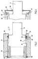
- the shoulder 20 delimits axially with the outer end face 31 of the support 16, a part 22 of smaller diameter, in which is made a throat ring 23 for housing an O-ring 24, the latter being applicable to a substantially sealed manner on a surface 26, cylindrical of revolution, of connector 11.
- the seal 24 prevents air from being sucked into the light 17 under the effect of the depression created by the fan 5 inside the machine during the operation of it. This air would be likely otherwise to lead with him Conductive dust that may impair electrical insulation.
- an additional seal 28, for example toric, can be engaged on each insulating tube 18, this seal 28 coming apply on the one hand against a surface of the shaft 4 and on the other hand against a chamfer support 16 to prevent air from circulating through the existing clearance around the tubes 18 in passages 7.
- the invention is not limited to a particular way of sealing and other types of sealing elements, elastomeric or not, can be used.
- FIG. 3 shows a connector 11 such that previously described and a support 16 'which differs from the previous one by the absence of the grooves rings 23, replaced by grooves 30 on the outer face 31.
- the grooves 30 serve to mount seals 32 each having a first part end 33 fixed in the corresponding groove 30, and a second end portion 34 applying tightly to the connector 11.
- the lining 32 can be made of elastomer or in other materials, being sufficiently flexible to be able to deform to accompany the displacement of the connector 11 relative to the support 16 '.
Landscapes
- Engineering & Computer Science (AREA)
- Power Engineering (AREA)
- Motor Or Generator Frames (AREA)
- Motor Or Generator Cooling System (AREA)
- Iron Core Of Rotating Electric Machines (AREA)
- Insulation, Fastening Of Motor, Generator Windings (AREA)
- Permanent Magnet Type Synchronous Machine (AREA)
- Connection Of Motors, Electrical Generators, Mechanical Devices, And The Like (AREA)
- Motor Or Generator Current Collectors (AREA)
- Control Of Ac Motors In General (AREA)
- Control Of Multiple Motors (AREA)
Description
- remplacer un support isolant, dans lequel une pluralité de connecteurs est disposée, chacun avec un jeu, par un support configuré pour recevoir au moins un élément d'étanchéité apte à empêcher une circulation d'air par ledit jeu, sous l'effet de la dépression créée par le ventilateur.
- la figure 1 représente, de manière schématique et partielle, en coupe axiale, une machine électrique tournante à laquelle l'invention peut s'appliquer,
- la figure 2 représente isolément, en coupe axiale et de manière schématique, un connecteur, et
- la figure 3 représente, de manière schématique et en coupe axiale, une variante de réalisation des moyens d'étanchéité.
Claims (10)
- Machine électrique tournante (1), comportantmachine caractérisée par le fait que le rotor comporte au moins un élément d'étanchéité (24 ; 32) apte à empêcher un passage d'air par le jeu existant entre le connecteur (11) et le support (16, 16'), sous l'effet de la dépression créée par le ventilateur (5).un rotor (2) bobiné,un ventilateur (5) tournant avec le rotor dans un carter (3),une pluralité de connecteurs électriques (11),au moins un support (16 ; 16') isolant, au moins un connecteur électrique (11) étant mobile par rapport au support (16, 16') et disposé avec un jeu dans celui-ci,
- Machine selon la revendication 1, caractérisée par le fait que le support (16, 16') comporte une pluralité de gorges annulaires (23) associées chacune à un connecteur (11), et par le fait qu'un joint annulaire (24) est placé dans chaque gorge (23), ce joint (24) étant apte à s'appliquer sur le connecteur (11) correspondant.
- Machine selon la revendication 2, caractérisée par le fait que le joint (24) est torique.
- Machine selon la revendication 1, caractérisée par le fait que l'élément d'étanchéité (24, 32) comporte une partie (33) au contact du support isolant (16') et une partie (34) au contact du connecteur (11), et entre les deux au moins une partie déformable.
- Machine selon l'une quelconque des revendications précédentes, caractérisée par le fait que les connecteurs (11) sont destinés à être reliés à des pistes annulaires conductrices (14) sur lesquelles frottent des charbons (15).
- Machine selon l'une quelconque des revendications précédentes, caractérisée par le fait que chaque connecteur (11) est fixé à une extrémité d'un câble électrique (10) relié à au moins un bobinage du rotor.
- Machine selon la revendication 6, caractérisée par le fait que chaque câble (10) est engagé dans un tube isolant (18), ce tube étant inséré dans un passage (7) de l'arbre (4).
- Machine selon la revendication 7, caractérisée par le fait qu'un joint annulaire supplémentaire (28) est engagé sur chaque tube isolant (18) pour empêcher une circulation d'air par le jeu existant entre le tube (18) et le passage correspondant (7) dans l'arbre (4) du rotor.
- Machine selon la revendication 8, caractérisée par le fait que le joint supplémentaire est un joint torique (28).
- Procédé de fabrication d'une machine telle que définie dans l'une quelconque des revendications précédentes, comportant l'étape suivante :remplacer un support isolant dans lequel une pluralité de connecteurs (11) est disposée, chacun avec un jeu, par un support (16 ; 16') isolant par ailleurs configuré pour recevoir au moins un élément d'étanchéité (24 ; 32) apte à empêcher une circulation d'air par le jeu entre chaque connecteur (11) et le support (16, 16'), sous l'effet d'une dépression créée par le ventilateur (5).
Applications Claiming Priority (2)
| Application Number | Priority Date | Filing Date | Title |
|---|---|---|---|
| FR0200620A FR2835110B1 (fr) | 2002-01-18 | 2002-01-18 | Machine electrique tournante |
| FR0200620 | 2002-01-18 |
Publications (3)
| Publication Number | Publication Date |
|---|---|
| EP1333560A2 EP1333560A2 (fr) | 2003-08-06 |
| EP1333560A3 EP1333560A3 (fr) | 2003-11-12 |
| EP1333560B1 true EP1333560B1 (fr) | 2005-08-24 |
Family
ID=8871350
Family Applications (1)
| Application Number | Title | Priority Date | Filing Date |
|---|---|---|---|
| EP03290105A Expired - Lifetime EP1333560B1 (fr) | 2002-01-18 | 2003-01-15 | Machine tournante électrique |
Country Status (6)
| Country | Link |
|---|---|
| EP (1) | EP1333560B1 (fr) |
| AT (1) | ATE303013T1 (fr) |
| DE (1) | DE60301357T2 (fr) |
| DK (1) | DK1333560T3 (fr) |
| ES (1) | ES2245766T3 (fr) |
| FR (1) | FR2835110B1 (fr) |
Family Cites Families (5)
| Publication number | Priority date | Publication date | Assignee | Title |
|---|---|---|---|---|
| DE840635C (de) * | 1944-01-01 | 1952-06-03 | Bosch Gmbh Robert | Einrichtung zum Halten und Abdichten von Waelzlagern |
| US3184625A (en) * | 1960-05-02 | 1965-05-18 | Chrysler Corp | Alternator rectifier unit |
| US3558942A (en) * | 1969-06-17 | 1971-01-26 | Gettys Mfg Co Inc | Dynamoelectric machine with improved cooling means |
| US5296772A (en) * | 1993-04-05 | 1994-03-22 | General Motors Corporation | Ventilated brush holder |
| JP3877899B2 (ja) * | 1999-03-09 | 2007-02-07 | 三菱電機株式会社 | 車両用交流発電機 |
-
2002
- 2002-01-18 FR FR0200620A patent/FR2835110B1/fr not_active Expired - Fee Related
-
2003
- 2003-01-15 DK DK03290105T patent/DK1333560T3/da active
- 2003-01-15 DE DE60301357T patent/DE60301357T2/de not_active Expired - Lifetime
- 2003-01-15 AT AT03290105T patent/ATE303013T1/de not_active IP Right Cessation
- 2003-01-15 ES ES03290105T patent/ES2245766T3/es not_active Expired - Lifetime
- 2003-01-15 EP EP03290105A patent/EP1333560B1/fr not_active Expired - Lifetime
Also Published As
| Publication number | Publication date |
|---|---|
| DK1333560T3 (da) | 2005-12-19 |
| EP1333560A3 (fr) | 2003-11-12 |
| FR2835110B1 (fr) | 2006-12-01 |
| ES2245766T3 (es) | 2006-01-16 |
| DE60301357T2 (de) | 2006-06-08 |
| ATE303013T1 (de) | 2005-09-15 |
| DE60301357D1 (de) | 2005-09-29 |
| EP1333560A2 (fr) | 2003-08-06 |
| FR2835110A1 (fr) | 2003-07-25 |
Similar Documents
| Publication | Publication Date | Title |
|---|---|---|
| EP1857657B1 (fr) | Boitier d'accessoires dans un moteur d'avion tel qu'un turboréacteur | |
| FR2666937A1 (fr) | Palier a roulement a contacts electriques tournants. | |
| EP1510697B1 (fr) | Pompe à vide | |
| KR102747920B1 (ko) | 제1 요소와 제2 요소의 전기적 연결을 위한 브러시 장치, 전기 기계 및 구동 장치 | |
| FR2851377A1 (fr) | Machine dynamoelectrique | |
| FR3141012A1 (fr) | Ensemble de brosse de mise à la terre | |
| FR2835110A1 (fr) | Machine electrique tournante | |
| EP2643918A1 (fr) | Ensemble monobloc regulateur de tension - porte-balais de machine electrique tournante et machine electrique tournante comprenant un tel ensemble | |
| CN114039444B (zh) | 一种电机及车辆 | |
| EP3220515A1 (fr) | Moteur électrique démontable | |
| FR2913543A1 (fr) | Module conduteur de courant et alternateur | |
| EP3926793A1 (fr) | Equipement électrique à tolérance thermique améliorée, et véhicule associé | |
| FR2573584A1 (fr) | Moteur a induit exterieur | |
| FR2710795A3 (fr) | Induit pour moteurs électriques avec ventilateur. | |
| FR3114926A1 (fr) | Machine électrique et procédé d'assemblage d'une telle machine | |
| FR2854004A1 (fr) | Machine electrique a refroidissement et essieu moteur equipe d'une telle machine | |
| FR2514581A1 (fr) | Dispositif de fixation des tetes de bobines de l'enroulement statorique d'une machine electrique | |
| FR3025559B1 (fr) | Ensemble d’elements pour une turbomachine | |
| FR3157980A1 (fr) | Un assemblage de roulements | |
| EP4590939A1 (fr) | Dispositif d'étanchéité et turbomachine comprenant le dispositif d'étanchéité | |
| WO2006111657A1 (fr) | Alternateur comprenant un roulement à bride de fixation | |
| FR3166491A1 (fr) | Dispositif d’alimentation électrique pour un rotor bobiné | |
| WO2024240627A1 (fr) | Dispositif de refroidissement d'un systeme d'excitation d'un rotor bobine sans-contact d'un moteur electrique pour vehicule automobile | |
| WO2025045424A1 (fr) | Bus d'alimentation électrique entre un rotor bobine et un systeme d'excitation sans contact | |
| EP2708747B1 (fr) | Boîtier d'un compresseur électrique |
Legal Events
| Date | Code | Title | Description |
|---|---|---|---|
| PUAI | Public reference made under article 153(3) epc to a published international application that has entered the european phase |
Free format text: ORIGINAL CODE: 0009012 |
|
| 17P | Request for examination filed |
Effective date: 20030120 |
|
| AK | Designated contracting states |
Designated state(s): AT BE BG CH CY CZ DE DK EE ES FI FR GB GR HU IE IT LI LU MC NL PT SE SI SK TR |
|
| AX | Request for extension of the european patent |
Extension state: AL LT LV MK RO |
|
| PUAL | Search report despatched |
Free format text: ORIGINAL CODE: 0009013 |
|
| AK | Designated contracting states |
Kind code of ref document: A3 Designated state(s): AT BE BG CH CY CZ DE DK EE ES FI FR GB GR HU IE IT LI LU MC NL PT SE SI SK TR |
|
| AX | Request for extension of the european patent |
Extension state: AL LT LV MK RO |
|
| RIC1 | Information provided on ipc code assigned before grant |
Ipc: 7H 02K 9/06 A Ipc: 7H 02K 9/12 B Ipc: 7H 02K 5/14 B |
|
| 17Q | First examination report despatched |
Effective date: 20031216 |
|
| AKX | Designation fees paid |
Designated state(s): AT BE BG CH CY CZ DE DK EE ES FI FR GB GR HU IE IT LI LU MC NL PT SE SI SK TR |
|
| GRAP | Despatch of communication of intention to grant a patent |
Free format text: ORIGINAL CODE: EPIDOSNIGR1 |
|
| GRAS | Grant fee paid |
Free format text: ORIGINAL CODE: EPIDOSNIGR3 |
|
| GRAA | (expected) grant |
Free format text: ORIGINAL CODE: 0009210 |
|
| AK | Designated contracting states |
Kind code of ref document: B1 Designated state(s): AT BE BG CH CY CZ DE DK EE ES FI FR GB GR HU IE IT LI LU MC NL PT SE SI SK TR |
|
| PG25 | Lapsed in a contracting state [announced via postgrant information from national office to epo] |
Ref country code: NL Free format text: LAPSE BECAUSE OF FAILURE TO SUBMIT A TRANSLATION OF THE DESCRIPTION OR TO PAY THE FEE WITHIN THE PRESCRIBED TIME-LIMIT Effective date: 20050824 Ref country code: GB Free format text: LAPSE BECAUSE OF FAILURE TO SUBMIT A TRANSLATION OF THE DESCRIPTION OR TO PAY THE FEE WITHIN THE PRESCRIBED TIME-LIMIT Effective date: 20050824 Ref country code: FI Free format text: LAPSE BECAUSE OF FAILURE TO SUBMIT A TRANSLATION OF THE DESCRIPTION OR TO PAY THE FEE WITHIN THE PRESCRIBED TIME-LIMIT Effective date: 20050824 Ref country code: AT Free format text: LAPSE BECAUSE OF FAILURE TO SUBMIT A TRANSLATION OF THE DESCRIPTION OR TO PAY THE FEE WITHIN THE PRESCRIBED TIME-LIMIT Effective date: 20050824 Ref country code: SK Free format text: LAPSE BECAUSE OF FAILURE TO SUBMIT A TRANSLATION OF THE DESCRIPTION OR TO PAY THE FEE WITHIN THE PRESCRIBED TIME-LIMIT Effective date: 20050824 Ref country code: CZ Free format text: LAPSE BECAUSE OF FAILURE TO SUBMIT A TRANSLATION OF THE DESCRIPTION OR TO PAY THE FEE WITHIN THE PRESCRIBED TIME-LIMIT Effective date: 20050824 Ref country code: SI Free format text: LAPSE BECAUSE OF FAILURE TO SUBMIT A TRANSLATION OF THE DESCRIPTION OR TO PAY THE FEE WITHIN THE PRESCRIBED TIME-LIMIT Effective date: 20050824 Ref country code: IE Free format text: LAPSE BECAUSE OF FAILURE TO SUBMIT A TRANSLATION OF THE DESCRIPTION OR TO PAY THE FEE WITHIN THE PRESCRIBED TIME-LIMIT Effective date: 20050824 |
|
| REG | Reference to a national code |
Ref country code: GB Ref legal event code: FG4D Free format text: NOT ENGLISH |
|
| REG | Reference to a national code |
Ref country code: CH Ref legal event code: EP |
|
| REG | Reference to a national code |
Ref country code: IE Ref legal event code: FG4D Free format text: LANGUAGE OF EP DOCUMENT: FRENCH |
|
| REF | Corresponds to: |
Ref document number: 60301357 Country of ref document: DE Date of ref document: 20050929 Kind code of ref document: P |
|
| PG25 | Lapsed in a contracting state [announced via postgrant information from national office to epo] |
Ref country code: GR Free format text: LAPSE BECAUSE OF FAILURE TO SUBMIT A TRANSLATION OF THE DESCRIPTION OR TO PAY THE FEE WITHIN THE PRESCRIBED TIME-LIMIT Effective date: 20051124 Ref country code: SE Free format text: LAPSE BECAUSE OF FAILURE TO SUBMIT A TRANSLATION OF THE DESCRIPTION OR TO PAY THE FEE WITHIN THE PRESCRIBED TIME-LIMIT Effective date: 20051124 Ref country code: BG Free format text: LAPSE BECAUSE OF FAILURE TO SUBMIT A TRANSLATION OF THE DESCRIPTION OR TO PAY THE FEE WITHIN THE PRESCRIBED TIME-LIMIT Effective date: 20051124 |
|
| REG | Reference to a national code |
Ref country code: DK Ref legal event code: T3 |
|
| REG | Reference to a national code |
Ref country code: ES Ref legal event code: FG2A Ref document number: 2245766 Country of ref document: ES Kind code of ref document: T3 |
|
| PG25 | Lapsed in a contracting state [announced via postgrant information from national office to epo] |
Ref country code: PT Free format text: LAPSE BECAUSE OF FAILURE TO SUBMIT A TRANSLATION OF THE DESCRIPTION OR TO PAY THE FEE WITHIN THE PRESCRIBED TIME-LIMIT Effective date: 20060124 |
|
| PG25 | Lapsed in a contracting state [announced via postgrant information from national office to epo] |
Ref country code: LU Free format text: LAPSE BECAUSE OF NON-PAYMENT OF DUE FEES Effective date: 20060131 Ref country code: BE Free format text: LAPSE BECAUSE OF NON-PAYMENT OF DUE FEES Effective date: 20060131 Ref country code: MC Free format text: LAPSE BECAUSE OF NON-PAYMENT OF DUE FEES Effective date: 20060131 |
|
| NLV1 | Nl: lapsed or annulled due to failure to fulfill the requirements of art. 29p and 29m of the patents act | ||
| PG25 | Lapsed in a contracting state [announced via postgrant information from national office to epo] |
Ref country code: HU Free format text: LAPSE BECAUSE OF FAILURE TO SUBMIT A TRANSLATION OF THE DESCRIPTION OR TO PAY THE FEE WITHIN THE PRESCRIBED TIME-LIMIT Effective date: 20060225 |
|
| GBV | Gb: ep patent (uk) treated as always having been void in accordance with gb section 77(7)/1977 [no translation filed] |
Effective date: 20050824 |
|
| REG | Reference to a national code |
Ref country code: IE Ref legal event code: FD4D |
|
| PLBE | No opposition filed within time limit |
Free format text: ORIGINAL CODE: 0009261 |
|
| STAA | Information on the status of an ep patent application or granted ep patent |
Free format text: STATUS: NO OPPOSITION FILED WITHIN TIME LIMIT |
|
| 26N | No opposition filed |
Effective date: 20060526 |
|
| PG25 | Lapsed in a contracting state [announced via postgrant information from national office to epo] |
Ref country code: LI Free format text: LAPSE BECAUSE OF NON-PAYMENT OF DUE FEES Effective date: 20070131 Ref country code: CH Free format text: LAPSE BECAUSE OF NON-PAYMENT OF DUE FEES Effective date: 20070131 |
|
| REG | Reference to a national code |
Ref country code: CH Ref legal event code: PL |
|
| BERE | Be: lapsed |
Owner name: MOTEURS LEROY-SOMER Effective date: 20060131 |
|
| PG25 | Lapsed in a contracting state [announced via postgrant information from national office to epo] |
Ref country code: EE Free format text: LAPSE BECAUSE OF FAILURE TO SUBMIT A TRANSLATION OF THE DESCRIPTION OR TO PAY THE FEE WITHIN THE PRESCRIBED TIME-LIMIT Effective date: 20050824 |
|
| PG25 | Lapsed in a contracting state [announced via postgrant information from national office to epo] |
Ref country code: TR Free format text: LAPSE BECAUSE OF FAILURE TO SUBMIT A TRANSLATION OF THE DESCRIPTION OR TO PAY THE FEE WITHIN THE PRESCRIBED TIME-LIMIT Effective date: 20050824 |
|
| PG25 | Lapsed in a contracting state [announced via postgrant information from national office to epo] |
Ref country code: CY Free format text: LAPSE BECAUSE OF FAILURE TO SUBMIT A TRANSLATION OF THE DESCRIPTION OR TO PAY THE FEE WITHIN THE PRESCRIBED TIME-LIMIT Effective date: 20050824 |
|
| PGFP | Annual fee paid to national office [announced via postgrant information from national office to epo] |
Ref country code: DK Payment date: 20140108 Year of fee payment: 12 Ref country code: DE Payment date: 20140124 Year of fee payment: 12 |
|
| PGFP | Annual fee paid to national office [announced via postgrant information from national office to epo] |
Ref country code: FR Payment date: 20131230 Year of fee payment: 12 Ref country code: IT Payment date: 20140128 Year of fee payment: 12 Ref country code: ES Payment date: 20131231 Year of fee payment: 12 |
|
| REG | Reference to a national code |
Ref country code: DE Ref legal event code: R119 Ref document number: 60301357 Country of ref document: DE |
|
| REG | Reference to a national code |
Ref country code: DK Ref legal event code: EBP Effective date: 20150131 |
|
| PG25 | Lapsed in a contracting state [announced via postgrant information from national office to epo] |
Ref country code: DE Free format text: LAPSE BECAUSE OF NON-PAYMENT OF DUE FEES Effective date: 20150801 |
|
| REG | Reference to a national code |
Ref country code: FR Ref legal event code: ST Effective date: 20150930 |
|
| PG25 | Lapsed in a contracting state [announced via postgrant information from national office to epo] |
Ref country code: FR Free format text: LAPSE BECAUSE OF NON-PAYMENT OF DUE FEES Effective date: 20150202 |
|
| PG25 | Lapsed in a contracting state [announced via postgrant information from national office to epo] |
Ref country code: IT Free format text: LAPSE BECAUSE OF NON-PAYMENT OF DUE FEES Effective date: 20150115 |
|
| PG25 | Lapsed in a contracting state [announced via postgrant information from national office to epo] |
Ref country code: DK Free format text: LAPSE BECAUSE OF NON-PAYMENT OF DUE FEES Effective date: 20150131 |
|
| REG | Reference to a national code |
Ref country code: ES Ref legal event code: FD2A Effective date: 20160226 |
|
| PG25 | Lapsed in a contracting state [announced via postgrant information from national office to epo] |
Ref country code: ES Free format text: LAPSE BECAUSE OF NON-PAYMENT OF DUE FEES Effective date: 20150116 |