EP1333528A1 - Antenna device and portable device - Google Patents
Antenna device and portable device Download PDFInfo
- Publication number
- EP1333528A1 EP1333528A1 EP00971810A EP00971810A EP1333528A1 EP 1333528 A1 EP1333528 A1 EP 1333528A1 EP 00971810 A EP00971810 A EP 00971810A EP 00971810 A EP00971810 A EP 00971810A EP 1333528 A1 EP1333528 A1 EP 1333528A1
- Authority
- EP
- European Patent Office
- Prior art keywords
- antenna
- fixing member
- power feed
- mobile phone
- boss
- Prior art date
- Legal status (The legal status is an assumption and is not a legal conclusion. Google has not performed a legal analysis and makes no representation as to the accuracy of the status listed.)
- Withdrawn
Links
Images


Classifications
-
- H—ELECTRICITY
- H01—ELECTRIC ELEMENTS
- H01Q—ANTENNAS, i.e. RADIO AERIALS
- H01Q9/00—Electrically-short antennas having dimensions not more than twice the operating wavelength and consisting of conductive active radiating elements
- H01Q9/04—Resonant antennas
- H01Q9/30—Resonant antennas with feed to end of elongated active element, e.g. unipole
- H01Q9/32—Vertical arrangement of element
-
- H—ELECTRICITY
- H01—ELECTRIC ELEMENTS
- H01Q—ANTENNAS, i.e. RADIO AERIALS
- H01Q1/00—Details of, or arrangements associated with, antennas
- H01Q1/12—Supports; Mounting means
- H01Q1/22—Supports; Mounting means by structural association with other equipment or articles
- H01Q1/24—Supports; Mounting means by structural association with other equipment or articles with receiving set
- H01Q1/241—Supports; Mounting means by structural association with other equipment or articles with receiving set used in mobile communications, e.g. GSM
- H01Q1/242—Supports; Mounting means by structural association with other equipment or articles with receiving set used in mobile communications, e.g. GSM specially adapted for hand-held use
- H01Q1/243—Supports; Mounting means by structural association with other equipment or articles with receiving set used in mobile communications, e.g. GSM specially adapted for hand-held use with built-in antennas
- H01Q1/244—Supports; Mounting means by structural association with other equipment or articles with receiving set used in mobile communications, e.g. GSM specially adapted for hand-held use with built-in antennas extendable from a housing along a given path
Definitions
- the present invention relates to an antenna device and a portable equipment, and more particularly, relates to an antenna device capable of preventing degradation in antenna gain during a call, and a portable equipment using the same.
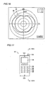
- FIG. 17 is a schematic diagram of a conventional mobile phone
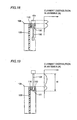
- Fig. 18 shows a schematic cross-sectional view taken along line XVIII-XVIII of Fig. 17 and a schematic graph of a current distribution in an antenna.
- the conventional mobile phone will now be described with reference to Figs. 17 and 18.
- a conventional mobile phone 101 includes in its main body a liquid crystal display portion 105, operation keys 106 for inputting a telephone number and the like, a speaker 104 and a microphone 103 for listening and speaking over the phone, respectively, and an antenna for communication with a base station.
- the antenna which is formed from a non-retracted antenna 151 and a linear extension antenna 102, is retractable in the main body of mobile phone 101.
- Figs. 17 and 18 show the state where the antenna is retracted in the main body of mobile phone 101. As shown in Figs.
- Fig. 19 shows a schematic cross sectional view of the state where the antenna is stretched out of the main body of the mobile phone of Fig. 17 and a schematic graph of a current distribution in the antenna.
- Fig. 19 corresponds to Fig. 18.
- the mobile phone includes a metal boss 150 in order to fix the antenna formed from non-retracted antenna 151 and linear extension antenna 102 to main body 108 in a stretchable manner.
- Metal boss 150 is a cylindrical boss having a hole, and the antenna is slidably inserted into the hole.
- the antenna is fixed by contact between the sidewall of the hole in metal boss 150 and the surface of the region of the antenna that is located under non-retracted antenna 151.
- the antenna is stretched as shown in Fig. 19 the antenna is fixed by contact between the sidewall of the hole in metal boss 150 and the surface of an antenna end 111 located at the end of the antenna.
- Metal boss 150 is fixed to a housing of main body 108 of mobile phone 101, and the like.
- Main body 105 of mobile phone 101 accommodates therein a circuit substrate 109 having transmitting/receiving circuit elements arranged thereon.
- a power feed pin 110 is mounted on the surface of circuit substrate 109. Power feed pin 110 contacts the outer peripheral surface of metal boss 150.
- circuit elements formed on circuit substrate 109 are electrically connected to non-retracted antenna 151 through power feed pin 110, metal boss 150 and the region of the antenna that is located under non-retracted antenna 151.
- the circuit elements formed on circuit substrate 109 are electrically connected to extension antenna 102 through power feed pin 110, metal boss 150 and antenna end 111.
- the conventional mobile phone of Figs. 17 to 19 has the following problems.
- metal boss 150 contacting the antenna is also a conductor, it acts as if it were a part of antenna when the antenna transmits and receives radio waves. For example, when a current flows through non-retracted antenna 151 of Fig. 18 (e.g., when non-retracted antenna 151 receives radio waves), it flows not only through non-retracted antenna 151 but also through metal boss 150. Moreover, when extension antenna 102 of Fig. 19 transmits and receives radio waves, a current flows not only through extension antenna 102 but also through metal boss 150. In other words, due to the presence of metal boss 150, non-retracted antenna 151 and extension antenna 102 act as if they were an antenna having an electrically discontinuous diameter.
- the current distribution in the antenna does not have a sinusoidal profile, as shown in Figs. 18 and 19.
- target impedance characteristics cannot be obtained even if the respective lengths of non-retracted antenna 151 and extension antenna 102 are designed so that they resonate in response to the radio waves of a target frequency.
- metal boss 150 increases a current value in the region near main body 108 of mobile phone 101. This results in increased electric-field and magnetic-field strengths (electromagnetic-field strength) in the region near main body 108.
- the user holds main body 108 of mobile phone 101 by hand and also holds main body 108 near the head for a phone call.
- metal boss 150 of main body 108 located in a region relatively close to the human body produces a relatively strong electromagnetic field, the presence of the human body affects the antenna gain more strongly. The antenna gain is thus reduced by the influence of the human body, resulting in degraded communication quality.
- metal boss 150 is formed from a metal having relatively larger specific gravity than a material of the housing of mobile phone 101 and the like such as plastic. Reduction in size and weight has been strongly demanded for mobile phone 101, and the use of a metal boss is one of the factors that hinder reduction in weight of the mobile phone.
- the present invention is made to solve the above problems, and it is an object of the present invention to provide an antenna device and a portable equipment that are capable of preventing degradation in communication quality.
- An antenna device includes a linear antenna, a fixing member and a power feed member.
- the fixing member is formed from a dielectric, and holds a portion of the antenna.
- the power feed member contacts the antenna.
- the fixing member holds the antenna in a movable manner.
- the fixing member such as a boss for holding a portion of the antenna is formed from a dielectric, whereby the antenna and the fixing member can be prevented from acting as if they were an antenna having an electrically discontinuous diameter.
- a current flowing through the antenna can be prevented from unnecessarily flowing through the fixing member.
- This enables the current distribution in the antenna to have an approximately sinusoidal profile, whereby the impedance characteristics of the antenna can be prevented from being varied from the designed characteristics.
- the fixing member is mounted to the main body of the portable equipment.
- the main body thereof is often held by hand and retained near the head of the human body.
- the fixing member is located in a region relatively close to the human body.
- the fixing member is formed from a dielectric, so that no current will unnecessarily flow through the fixing member. Accordingly, an electromagnetic field that is conventionally formed by the current flowing through the fixing member will not be formed.
- the fixing member is formed from a dielectric, a material such as a resin having relatively smaller specific gravity than a metal used in the conventional example can be used as a material of the fixing member.
- a material such as a resin having relatively smaller specific gravity than a metal used in the conventional example
- the antenna device of the present invention to a portable radio equipment such as a mobile phone, the weight of the portable radio equipment can be reduced as compared to the case of using a metal fixing member.
- the fixing member may have an opening for exposing a part of a surface of the portion of the antenna that is held by the fixing member, and the power feed member may contact the part of the surface of the antenna through the opening.
- electrical connection between the power feed member and the antenna can be implemented with the fixing member having a relatively simple structure, i.e., the fixing member having an opening.
- the structure of the antenna device can be simplified.
- complicated processing is not required such as embedding the power feed member into the wall of the fixing member, enabling reduction in manufacturing costs of the antenna device.
- the antenna may include an extended portion extending out of the fixing member, and the power feed member may be mounted in contact with the extended portion.
- the fixing member is preferably a cylindrical member having a hole, and the antenna is preferably inserted in the hole of the cylindrical fixing member.
- the position of the antenna relative to the fixing member can be easily determined by making that region in contact with the sidewall of the hole in the fixing member.
- the power feed member may contact the antenna within the hole of the fixing member.
- the volume of the region occupied by the antenna device can be reduced as compared to the case where the power feed member and the antenna contact each other outside the fixing member. As a result, reduction in size of the antenna device can be achieved.
- the fixing member is preferably formed from a resin.
- the fixing member can be easily formed due to better processability of the resin than that of a metal or the like.
- a portable equipment includes a housing, a linear antenna, a fixing member and a power feed member.
- the fixing member is formed from a dielectric, and holds a portion of the antenna so as to fix the antenna to the housing.
- the fixing member holds the antenna in a movable manner.
- the power feed member contacts the antenna.
- the fixing member such as a boss for holding a portion of the antenna is formed from a dielectric, whereby the antenna and the fixing member can be prevented from acting as if they were an antenna having an electrically discontinuous diameter.
- a current flowing through the antenna can be prevented from unnecessarily flowing through the fixing member.
- This enables the current distribution in the antenna to have an approximately sinusoidal profile, whereby the impedance characteristics of the antenna can be prevented from being varied from the designed characteristics.
- degradation in communication quality can be prevented in the portable equipment such as a mobile phone and a radio device.
- the fixing member is mounted to the main body of the portable equipment.
- the main body thereof is often held by hand and retained near the head of the human body.
- the fixing member is located in a region relatively close to the human body.
- the fixing member is formed from a dielectric, so that no current will unnecessarily flow through the fixing member. Accordingly, an electromagnetic field that is conventionally formed by the current flowing through the fixing member will not be formed. Since a current flowing through the antenna thus produces a weaker electromagnetic field in the region relatively close to the human body as compared to the conventional example, characteristics such as antenna gain can be less affected by the presence of the human body. As a result, the characteristics such as antenna gain can be prevented from being degraded by the influence of the human body.
- the fixing member is formed from a dielectric, a material such as a resin having relatively smaller specific gravity than a metal used in the conventional example can be used as a material of the fixing member. As a result, the weight of the portable equipment can be reduced as compared to the case of using a metal fixing member.
- the fixing member may have an opening for exposing a part of a surface of the portion of the antenna that is held by the fixing member, and the power feed member may contact the part of the surface of the antenna through the opening.
- electrical connection between the power feed member and the antenna can be implemented with the fixing member having a relatively simple structure, i.e., the fixing member having an opening.
- the structure of the portable equipment can be simplified.
- complicated processing is not required such as embedding the power feed member into the wall of the fixing member, enabling reduction in manufacturing costs of the portable equipment.
- the antenna may include an extended portion extending out of the fixing member within the housing, and the power feed member may be mounted in contact with the extended portion.
- the fixing member is preferably a cylindrical member having a hole, and the antenna is preferably inserted in the hole of the cylindrical fixing member.
- the position of the antenna relative to the fixing member can be easily determined by making that region in contact with the sidewall of the hole in the fixing member.
- the power feed member may contact the antenna within the hole of the fixing member.
- the volume of the region required for the connection between the power feed member and the antenna can be reduced as compared to the case where the power feed member and the antenna contact each other outside the fixing member. As a result, reduction in size of the portable equipment can be achieved.
- the portable equipment may further include a substrate held within the housing.
- the power feed member may include a conductor member contacting the portion of the antenna that is held by the fixing member, and being connected to the fixing member, and an electrode contacting the conductor member and mounted on the substrate.
- the antenna can be electrically connected to circuit elements on the substrate through the conductor member and the electrode. Since the electrode need only have a contact surface that contacts the conductor member, a simply structured conductor member on the substrate such as a conductor film or electrode plate mounted on the substrate can be used as the electrode. As a result, the structure of the substrate can be simplified as compared to the case where a structure such as a power feed pin is mounted on the substrate.
- the fixing member is preferably formed from a resin.
- the fixing member can be easily formed due to better processability of the resin than that of a metal or the like.
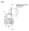
- a mobile phone 1 includes a main body 8 and a linear antenna 2 mounted to main body 8. Elements such as a liquid crystal display portion 5, a speaker 4, a microphone 3 and operation keys 6 for inputting a telephone number and the like are arranged at the surface of main body 8.
- a resin case 16 forming a housing of main body 8 holds therein a circuit substrate 9 as a substrate having control portions such as a transmitting/receiving circuit arranged thereon.
- a boss 7 formed from a resin, i.e., a dielectric is mounted to case 16 as a fixing member.
- Boss 7 is a cylindrical boss having a hole at the center for receiving antenna 2.
- boss 7 can be easily formed due to better processability of the resin than that of a metal or the like.
- the hole in boss 7 is a through hole extending from the outer periphery of main body 8 to the inner periphery thereof.
- Antenna 2 is slidable along the hole of boss 7 and thus retractable in main body 8.
- Figs. 1 and 2 show the state where antenna 2 is stretched out of main body 8. When antenna 2 is stretched out of main body 8, the outer peripheral surface of an antenna end 11 connected to the lower portion of antenna 2 fixedly contacts the inner wall of boss 7, whereby antenna 2 is prevented from slipping out of main body 2.
- antenna end 11 i.e., a region of the antenna for fixing the antenna to boss 7
- antenna end 11 has an outer diameter that is approximately the same as the hole diameter of boss 7
- the position of antenna 2 relative to boss 7 can be easily determined by making the surface of antenna end 11 in contact with the sidewall of the hole in boss 7.
- a metal spring 12 of a power feed member extends through the sidewall of boss 7 from the inner peripheral surface of the hole in boss 7 to the outer peripheral surface of boss 7, and contacts antenna end 11 of antenna 2.
- One end of metal spring 12 thus contacts antenna end 11.
- the other end of metal spring 12 sticks out of the outer peripheral surface of boss 7 and contacts a power feed pin 10 of the power feed member, which is mounted on the surface of circuit substrate 9.
- Antenna 2, antenna end 11, boss 7, metal spring 12, power feed pin 10 and circuit substrate 9 form an antenna device.
- boss 7 for holding part of the antenna i.e., antenna end 11, is formed from a resin as a dielectric, whereby antenna 2 and boss 7 can be prevented from acting as if they were an antenna having an electrically discontinuous diameter.
- a current flowing through antenna 2 can be prevented from unnecessarily flowing through boss 7.
- This enables the current distribution in antenna 2 to have an approximately sinusoidal profile as shown in Fig. 1, whereby the impedance characteristics of the antenna can be prevented from being varied from the designed characteristics. As a result, degradation in communication quality of mobile phone 1 can be prevented.
- boss 7 is located in a region relatively close to the human body.
- boss 7 is formed from a dielectric such as a resin, so that no current will unnecessarily flow through boss 7. Accordingly, an electromagnetic field that is conventionally formed by the current flowing through boss 7 will not be formed. Since a current flowing through antenna 2 thus produces a weaker electromagnetic field in the region relatively close to the human body as compared to the conventional example, characteristics such as gain of antenna 2 can be less affected by the presence of the human body. As a result, the characteristics such as gain of antenna 2 can be prevented from being degraded by the influence of the human body.
- boss 7 is formed from a resin having relatively smaller specific gravity than a metal used in the conventional example, the weight of mobile phone 1 can be reduced as compared to the mobile phone using metal boss 7.
- a modification of the first embodiment of the mobile phone according to the present invention basically has the same structure as that of the mobile phone shown in Figs. 1 and 2.
- Fig. 3 corresponds to Fig. 2.
- the mobile phone of Fig. 3 has a boss opening 13 formed as a through hole in the sidewall of resin boss 7.
- Boss opening 13 exposes a part of the surface of antenna end 11 located in the lower portion of antenna 2.
- the tip of power feed pin 10 directly contacts the surface of antenna end 11 through boss opening 13.
- power feed pin 10 and antenna 2 are directly electrically connected to each other through antenna end 11.
- Fig. 4 corresponds to Fig. 2.
- the mobile phone basically has the same structure as that of the mobile phone shown in Figs. 1 and 2.
- power feed pin 10 on the surface of substrate 9 is replaced with a power feed pad 14 as an electrode formed from a simple conductor film or the like.
- Metal spring 12 as a power feed member extends through the sidewall of boss 7 so that one end of metal spring 12 contacts antenna end 11 and the other end thereof directly contacts power feed pad 14.
- antenna 2 can be electrically connected to the circuit elements on circuit substrate 9 through metal spring 12 as a conductor member and simply structured power feed pad 14 as an electrode having a conductor film formed on the surface.
- the structure of circuit substrate 9 can be simplified as compared to the case where a structure such as power feed pin 10 is mounted on circuit substrate 9.
- Fig. 5 corresponds to Fig. 3.
- the mobile phone basically has the same structure as that of the first embodiment of the mobile phone according to the present invention.
- the mobile phone of Fig. 5 does not include a metal spring extending through the sidewall of resin boss 7.
- an antenna-end power feed portion 15 extends to the outside of boss 7 as an extended portion of antenna 2.
- Power feed pin 10 is mounted on the surface of substrate 9 so as to contact antenna-end power feed portion 15. Power feed pin 10 on substrate 9 is thus electrically connected to antenna 2 through antenna-end power feed portion 15.
- an antenna device is formed from substrate 9 and linear antenna 2 mounted thereto.
- Substrate 9 has a length L1 of 116 mm and a width L2 of 36 mm.
- Antenna 2 has a height W1 of 6 mm and a length W2 of 66 mm.
- the extension direction of antenna 2 is defined as +Z direction in the figure.
- the direction from right to left in Fig. 6 is defined as +Y direction.
- the direction from the back of the plane of the figure toward the front thereof is defined as +X direction.
- the antenna device of Fig. 6 was first placed on a table 150.
- the antenna device was placed such that the extension direction of antenna 2, i.e., +Z direction, and +X direction were approximately perpendicular to the vertical direction shown by arrow 140. Accordingly, +Y direction was approximately parallel to the vertical direction shown by arrow 140.
- Table 150 is rotatable in the direction shown by arrow R.
- radio waves having a frequency of 1.95 GHz were radiated from the antenna device through antenna 2 at a prescribed output.
- table 150 was rotated in the direction shown by arrow R.
- radio waves were radiated from antenna 2 as shown by arrow 151.
- the electric field strength of the radio waves was measured with a measuring antenna 160. The electric field strength of the radio waves was thus obtained for vertically polarized waves in the direction shown by arrow V and horizontally polarized waves in the direction shown by arrow H.
- a dipole antenna 170 was placed on table 150.
- Dipole antenna 170 has a power feed point 171 in the center, which is connected to a coaxial cable 172.
- Coaxial cable 172 is connected to a prescribed radio transmitting/receiving portion.
- Dipole antenna 170 was placed so as to extend approximately in parallel with the vertical direction shown by arrow 140.
- radio waves having a frequency of 1.95 GHz were radiated from dipole antenna 170.
- the radio waves were thus radiated from dipole antenna 170 as shown by arrow 152.
- These radio waves are vertically polarized waves of the direction shown by arrow V.
- the electric field strength of the radio waves was measured with measuring antenna 160.
- dipole antenna 170 was placed on table 150.
- Dipole antenna 170 was placed so as to extend approximately perpendicularly to the vertical direction shown by arrow 140.
- Dipole antenna 170 has power feed point 171 in the center. Power feed point 171 is connected to coaxial cable 172.
- radio waves having a frequency of 1.95 GHz were radiated from dipole antenna 170 as shown by arrow 153. These radio waves are horizontally polarized waves of the direction shown by arrow H. The electric field strength of the radio waves was measured with measuring antenna 160.
- FIG. 10 is a graph showing the radiation pattern of the antenna device of Fig. 6.
- solid line 17 indicates the gain of the vertically polarized wave components of the radio waves radiated from antenna 2 of Fig. 7 for the electric field strength of the vertically polarized waves radiated from dipole antenna 170 in the step of Fig. 8.
- the antenna device of Fig. 6 is a half-wave antenna having a length (W1 + W2) of 72 mm which is approximately equal to a theoretical antenna length.
- This antenna device has an excellent radiation pattern as shown in Fig. 10.
- a division corresponds to 10 dB.
- a point on X-axis, i.e., the abscissa of Fig. 10 is a point indicating the gain in the state where X-axis in Fig. 6 extends toward measuring antenna 160
- a point on Z-axis i.e., the ordinate, is a point indicating the gain in the state where Z-axis in Fig. 6 extends toward measuring antenna 160.
- Figs. 11 to 16 show the radiation patterns of the conventional mobile phone whose linear antenna 102 has a length of 45 mm, 48 mm, 55 mm, 60 mm, 62.5 mm and 65 mm, respectively.
- solid lines 19, 21, 23, 25, 27, 29 show the gain of the vertically polarized wave components of the radio waves radiated from antenna 102 for the electric field strength of the vertically polarized waves radiated from dipole antenna 170 in the step of Fig.
- the conventional mobile phone has a relatively good radiation pattern when antenna 102 has a length of 55 to 60 mm.
- this length of antenna 102 is different from a theoretically required value. This seems to result from the fact that a relatively large current flowing through metal boss 150 varies the current distribution in antenna 102.
- the presence of metal boss 150 necessitates measurement of the radiation patterns for various antenna lengths as shown in Figs. 11 to 16 in order to obtain an optimal radiation pattern.
- linear antenna 2 can be regarded as a linear antenna having an approximately uniform diameter. Therefore, an excellent radiation pattern can be obtained by using antenna 102 having a length relatively close to a theoretical value.
- the antenna device and the portable equipment according to the present invention can be utilized not only in the mobile phones but also in the field of portable information terminals such as a personal computer having a communication function.
Landscapes
- Engineering & Computer Science (AREA)
- Computer Networks & Wireless Communication (AREA)
- Support Of Aerials (AREA)
- Telephone Set Structure (AREA)
Abstract
The antenna device includes a linear antenna (2, 11, 15), a fixing
member (7), and a power feed member (10, 12, 14). The fixing member (7)
is formed from a dielectric, and holds a portion (11) of the antenna. The
power feed member (12, 10) contacts the antenna (11, 15). The fixing
member (7) holds the antenna (2, 11, 15) in a movable manner.
Description
The present invention relates to an antenna device and a portable
equipment, and more particularly, relates to an antenna device capable of
preventing degradation in antenna gain during a call, and a portable
equipment using the same.
Recently, mobile phones are increasingly becoming widespread. Fig.
17 is a schematic diagram of a conventional mobile phone, and Fig. 18
shows a schematic cross-sectional view taken along line XVIII-XVIII of Fig.
17 and a schematic graph of a current distribution in an antenna. The
conventional mobile phone will now be described with reference to Figs. 17
and 18.
Referring to Figs. 17 and 18, a conventional mobile phone 101
includes in its main body a liquid crystal display portion 105, operation
keys 106 for inputting a telephone number and the like, a speaker 104 and
a microphone 103 for listening and speaking over the phone, respectively,
and an antenna for communication with a base station. The antenna,
which is formed from a non-retracted antenna 151 and a linear extension
antenna 102, is retractable in the main body of mobile phone 101. Figs. 17
and 18 show the state where the antenna is retracted in the main body of
mobile phone 101. As shown in Figs. 17 and 18, when the antenna is
retracted in main body 108 of mobile phone 101, non-retracted antenna 151
sticks out of main body 108, and extension antenna 102, is accommodated
within main body 108. On the other hand, when mobile phone 101 is used
for a phone call or the like, the antenna is stretched out of main body 108 of
mobile phone 101 as shown in Fig. 19 so that extension antenna 102 is
exposed outside main body 108. Fig. 19 shows a schematic cross sectional
view of the state where the antenna is stretched out of the main body of the
mobile phone of Fig. 17 and a schematic graph of a current distribution in
the antenna. Fig. 19 corresponds to Fig. 18.
Referring to Figs. 18 and 19, the mobile phone includes a metal boss
150 in order to fix the antenna formed from non-retracted antenna 151 and
linear extension antenna 102 to main body 108 in a stretchable manner.
Metal boss 150 is a cylindrical boss having a hole, and the antenna is
slidably inserted into the hole. When the antenna is retracted as shown in
Fig. 18, the antenna is fixed by contact between the sidewall of the hole in
metal boss 150 and the surface of the region of the antenna that is located
under non-retracted antenna 151. When the antenna is stretched as
shown in Fig. 19, the antenna is fixed by contact between the sidewall of
the hole in metal boss 150 and the surface of an antenna end 111 located at
the end of the antenna.
When the antenna is retracted as shown in Figs. 17 and 18, the
circuit elements formed on circuit substrate 109 are electrically connected
to non-retracted antenna 151 through power feed pin 110, metal boss 150
and the region of the antenna that is located under non-retracted antenna
151. Moreover, when the antenna is stretched as shown in Fig. 19, the
circuit elements formed on circuit substrate 109 are electrically connected
to extension antenna 102 through power feed pin 110, metal boss 150 and
antenna end 111.
However, the conventional mobile phone of Figs. 17 to 19 has the
following problems.
Since metal boss 150 contacting the antenna is also a conductor, it
acts as if it were a part of antenna when the antenna transmits and
receives radio waves. For example, when a current flows through non-retracted
antenna 151 of Fig. 18 (e.g., when non-retracted antenna 151
receives radio waves), it flows not only through non-retracted antenna 151
but also through metal boss 150. Moreover, when extension antenna 102
of Fig. 19 transmits and receives radio waves, a current flows not only
through extension antenna 102 but also through metal boss 150. In other
words, due to the presence of metal boss 150, non-retracted antenna 151
and extension antenna 102 act as if they were an antenna having an
electrically discontinuous diameter. Accordingly, the current distribution
in the antenna does not have a sinusoidal profile, as shown in Figs. 18 and
19. With such a non-sinusoidal current distribution in the antenna, target
impedance characteristics cannot be obtained even if the respective lengths
of non-retracted antenna 151 and extension antenna 102 are designed so
that they resonate in response to the radio waves of a target frequency.
Moreover, as shown in Figs. 18 and 19, the presence of metal boss
150 increases a current value in the region near main body 108 of mobile
phone 101. This results in increased electric-field and magnetic-field
strengths (electromagnetic-field strength) in the region near main body 108.
The user holds main body 108 of mobile phone 101 by hand and also holds
main body 108 near the head for a phone call. In this case, since metal
boss 150 of main body 108 located in a region relatively close to the human
body produces a relatively strong electromagnetic field, the presence of the
human body affects the antenna gain more strongly. The antenna gain is
thus reduced by the influence of the human body, resulting in degraded
communication quality.
Moreover, metal boss 150 is formed from a metal having relatively
larger specific gravity than a material of the housing of mobile phone 101
and the like such as plastic. Reduction in size and weight has been
strongly demanded for mobile phone 101, and the use of a metal boss is one
of the factors that hinder reduction in weight of the mobile phone.
The present invention is made to solve the above problems, and it is
an object of the present invention to provide an antenna device and a
portable equipment that are capable of preventing degradation in
communication quality.
It is another object of the present invention to provide an antenna
device and a portable equipment that enable reduction in weight.
An antenna device according to one aspect of the present invention
includes a linear antenna, a fixing member and a power feed member.
The fixing member is formed from a dielectric, and holds a portion of the
antenna. The power feed member contacts the antenna. The fixing
member holds the antenna in a movable manner.
In this structure, the fixing member such as a boss for holding a
portion of the antenna is formed from a dielectric, whereby the antenna
and the fixing member can be prevented from acting as if they were an
antenna having an electrically discontinuous diameter. As a result, a
current flowing through the antenna can be prevented from unnecessarily
flowing through the fixing member. This enables the current distribution
in the antenna to have an approximately sinusoidal profile, whereby the
impedance characteristics of the antenna can be prevented from being
varied from the designed characteristics.
When the antenna device of the present invention is applied to a
portable equipment such as a mobile phone, the fixing member is mounted
to the main body of the portable equipment. In using such a portable
equipment, the main body thereof is often held by hand and retained near
the head of the human body. In other words, the fixing member is located
in a region relatively close to the human body. In the antenna device of
the present invention, the fixing member is formed from a dielectric, so that
no current will unnecessarily flow through the fixing member.
Accordingly, an electromagnetic field that is conventionally formed by the
current flowing through the fixing member will not be formed. Since a
current flowing through the antenna thus produces a weaker
electromagnetic field in the region relatively close to the human body as
compared to the conventional example, characteristics such as antenna
gain can be less affected by the presence of the human body. As a result,
the characteristics such as antenna gain can be prevented from being
degraded by the influence of the human body.
Moreover, since the fixing member is formed from a dielectric, a
material such as a resin having relatively smaller specific gravity than a
metal used in the conventional example can be used as a material of the
fixing member. As a result, by applying the antenna device of the present
invention to a portable radio equipment such as a mobile phone, the weight
of the portable radio equipment can be reduced as compared to the case of
using a metal fixing member.
In the antenna device according to the aforementioned one aspect,
the fixing member may have an opening for exposing a part of a surface of
the portion of the antenna that is held by the fixing member, and the power
feed member may contact the part of the surface of the antenna through the
opening.
In this case, electrical connection between the power feed member
and the antenna can be implemented with the fixing member having a
relatively simple structure, i.e., the fixing member having an opening. As
a result, the structure of the antenna device can be simplified. Moreover,
complicated processing is not required such as embedding the power feed
member into the wall of the fixing member, enabling reduction in
manufacturing costs of the antenna device.
In the antenna device according to the aforementioned one aspect,
the antenna may include an extended portion extending out of the fixing
member, and the power feed member may be mounted in contact with the
extended portion.
In this case, since the contact between the antenna and the power
feed member is ensured in a region other than the region where the fixing
member is located, connection between the antenna and the power feed
member can be assured without requiring special processing such as
providing the fixing member with a conductive wire that contacts the
antenna. This enables a further simplified structure of the antenna device
and reduction in manufacturing costs thereof.
In the antenna device of the aforementioned one aspect, the fixing
member is preferably a cylindrical member having a hole, and the antenna
is preferably inserted in the hole of the cylindrical fixing member.
In this case, when a region of the antenna that is fixed to the fixing
member has an outer diameter that is approximately the same as the hole
diameter of the fixing member, the position of the antenna relative to the
fixing member can be easily determined by making that region in contact
with the sidewall of the hole in the fixing member.
In the antenna device according to the aforementioned one aspect,
the power feed member may contact the antenna within the hole of the
fixing member.
In this case, since the power feed member and the antenna contact
each other within the fixing member, the volume of the region occupied by
the antenna device can be reduced as compared to the case where the power
feed member and the antenna contact each other outside the fixing member.
As a result, reduction in size of the antenna device can be achieved.
In the antenna device according to the aforementioned one aspect,
the fixing member is preferably formed from a resin.
In this case, the fixing member can be easily formed due to better
processability of the resin than that of a metal or the like.
A portable equipment according to another aspect of the present
invention includes a housing, a linear antenna, a fixing member and a
power feed member. The fixing member is formed from a dielectric, and
holds a portion of the antenna so as to fix the antenna to the housing. The
fixing member holds the antenna in a movable manner. The power feed
member contacts the antenna.
In this structure, the fixing member such as a boss for holding a
portion of the antenna is formed from a dielectric, whereby the antenna
and the fixing member can be prevented from acting as if they were an
antenna having an electrically discontinuous diameter. As a result, a
current flowing through the antenna can be prevented from unnecessarily
flowing through the fixing member. This enables the current distribution
in the antenna to have an approximately sinusoidal profile, whereby the
impedance characteristics of the antenna can be prevented from being
varied from the designed characteristics. As a result, degradation in
communication quality can be prevented in the portable equipment such as
a mobile phone and a radio device.
Since the antenna is mounted to the portable equipment, the fixing
member is mounted to the main body of the portable equipment. In using
such a portable equipment, the main body thereof is often held by hand and
retained near the head of the human body. In other words, the fixing
member is located in a region relatively close to the human body. In the
portable equipment of the present invention, the fixing member is formed
from a dielectric, so that no current will unnecessarily flow through the
fixing member. Accordingly, an electromagnetic field that is
conventionally formed by the current flowing through the fixing member
will not be formed. Since a current flowing through the antenna thus
produces a weaker electromagnetic field in the region relatively close to the
human body as compared to the conventional example, characteristics such
as antenna gain can be less affected by the presence of the human body.
As a result, the characteristics such as antenna gain can be prevented from
being degraded by the influence of the human body.
Moreover, since the fixing member is formed from a dielectric, a
material such as a resin having relatively smaller specific gravity than a
metal used in the conventional example can be used as a material of the
fixing member. As a result, the weight of the portable equipment can be
reduced as compared to the case of using a metal fixing member.
In the portable equipment according to the aforementioned another
aspect, the fixing member may have an opening for exposing a part of a
surface of the portion of the antenna that is held by the fixing member, and
the power feed member may contact the part of the surface of the antenna
through the opening.
In this case, electrical connection between the power feed member
and the antenna can be implemented with the fixing member having a
relatively simple structure, i.e., the fixing member having an opening. As
a result, the structure of the portable equipment can be simplified.
Moreover, complicated processing is not required such as embedding the
power feed member into the wall of the fixing member, enabling reduction
in manufacturing costs of the portable equipment.
In the portable equipment according to the aforementioned another
aspect, the antenna may include an extended portion extending out of the
fixing member within the housing, and the power feed member may be
mounted in contact with the extended portion.
In this case, since the contact between the antenna and the power
feed member is ensured in a region other than the region where the fixing
member is located, connection between the antenna and the power feed
member can be assured without requiring special processing for the fixing
member such as providing the fixing member with a conductive wire that
contacts the antenna. This enables a further simplified structure of the
portable equipment and reduction in manufacturing costs thereof.
In the portable equipment according to the aforementioned another
aspect, the fixing member is preferably a cylindrical member having a hole,
and the antenna is preferably inserted in the hole of the cylindrical fixing
member.
In this case, when a region of the antenna that is fixed to the fixing
member has an outer diameter that is approximately the same as the hole
diameter of the fixing member, the position of the antenna relative to the
fixing member can be easily determined by making that region in contact
with the sidewall of the hole in the fixing member.
In the portable equipment according to the aforementioned another
aspect, the power feed member may contact the antenna within the hole of
the fixing member.
In this case, since the power feed member and the antenna contact
each other within the fixing member, the volume of the region required for
the connection between the power feed member and the antenna can be
reduced as compared to the case where the power feed member and the
antenna contact each other outside the fixing member. As a result,
reduction in size of the portable equipment can be achieved.
The portable equipment according to the aforementioned another
aspect may further include a substrate held within the housing. The
power feed member may include a conductor member contacting the portion
of the antenna that is held by the fixing member, and being connected to
the fixing member, and an electrode contacting the conductor member and
mounted on the substrate.
In this case, the antenna can be electrically connected to circuit
elements on the substrate through the conductor member and the electrode.
Since the electrode need only have a contact surface that contacts the
conductor member, a simply structured conductor member on the substrate
such as a conductor film or electrode plate mounted on the substrate can be
used as the electrode. As a result, the structure of the substrate can be
simplified as compared to the case where a structure such as a power feed
pin is mounted on the substrate.
In the portable equipment according to the aforementioned another
aspect, the fixing member is preferably formed from a resin.
In this case, the fixing member can be easily formed due to better
processability of the resin than that of a metal or the like.
Hereinafter, embodiments of the present invention will be described
with reference to the accompanying drawings. Note that, in the following
figures, the same or corresponding portions are denoted with the same
reference numerals, and description thereof will not be repeated.
The first embodiment of a mobile phone as a portable equipment of
the present invention will now be described with reference to Figs. 1 and 2.
Referring to Figs. 1 and 2, a mobile phone 1 includes a main body 8
and a linear antenna 2 mounted to main body 8. Elements such as a
liquid crystal display portion 5, a speaker 4, a microphone 3 and operation
keys 6 for inputting a telephone number and the like are arranged at the
surface of main body 8. A resin case 16 forming a housing of main body 8
holds therein a circuit substrate 9 as a substrate having control portions
such as a transmitting/receiving circuit arranged thereon. In order to fix
antenna 2 to main body 8, a boss 7 formed from a resin, i.e., a dielectric, is
mounted to case 16 as a fixing member. Boss 7 is a cylindrical boss having
a hole at the center for receiving antenna 2. Desirably, ABS resin
(acrylonitrile-butadien-styrene copolymer) is used for boss 7. In this case,
boss 7 can be easily formed due to better processability of the resin than
that of a metal or the like. The hole in boss 7 is a through hole extending
from the outer periphery of main body 8 to the inner periphery thereof.
Antenna 2 is slidable along the hole of boss 7 and thus retractable in main
body 8. Note that Figs. 1 and 2 show the state where antenna 2 is
stretched out of main body 8. When antenna 2 is stretched out of main
body 8, the outer peripheral surface of an antenna end 11 connected to the
lower portion of antenna 2 fixedly contacts the inner wall of boss 7,
whereby antenna 2 is prevented from slipping out of main body 2. In this
way, when antenna end 11, i.e., a region of the antenna for fixing the
antenna to boss 7, has an outer diameter that is approximately the same as
the hole diameter of boss 7, the position of antenna 2 relative to boss 7 can
be easily determined by making the surface of antenna end 11 in contact
with the sidewall of the hole in boss 7.
A metal spring 12 of a power feed member extends through the
sidewall of boss 7 from the inner peripheral surface of the hole in boss 7 to
the outer peripheral surface of boss 7, and contacts antenna end 11 of
antenna 2. One end of metal spring 12 thus contacts antenna end 11.
The other end of metal spring 12 sticks out of the outer peripheral surface
of boss 7 and contacts a power feed pin 10 of the power feed member, which
is mounted on the surface of circuit substrate 9. Antenna 2, antenna end
11, boss 7, metal spring 12, power feed pin 10 and circuit substrate 9 form
an antenna device.
In this structure, boss 7 for holding part of the antenna, i.e., antenna
end 11, is formed from a resin as a dielectric, whereby antenna 2 and boss 7
can be prevented from acting as if they were an antenna having an
electrically discontinuous diameter. As a result, a current flowing through
antenna 2 can be prevented from unnecessarily flowing through boss 7.
This enables the current distribution in antenna 2 to have an
approximately sinusoidal profile as shown in Fig. 1, whereby the
impedance characteristics of the antenna can be prevented from being
varied from the designed characteristics. As a result, degradation in
communication quality of mobile phone 1 can be prevented.
In using such a mobile phone 1, main body 8 is often held by hand
and retained near the head of the human body. In other words, boss 7 is
located in a region relatively close to the human body. In mobile phone 1
of Figs. 1 and 2, boss 7 is formed from a dielectric such as a resin, so that no
current will unnecessarily flow through boss 7. Accordingly, an
electromagnetic field that is conventionally formed by the current flowing
through boss 7 will not be formed. Since a current flowing through
antenna 2 thus produces a weaker electromagnetic field in the region
relatively close to the human body as compared to the conventional
example, characteristics such as gain of antenna 2 can be less affected by
the presence of the human body. As a result, the characteristics such as
gain of antenna 2 can be prevented from being degraded by the influence of
the human body.
Moreover, since boss 7 is formed from a resin having relatively
smaller specific gravity than a metal used in the conventional example, the
weight of mobile phone 1 can be reduced as compared to the mobile phone
using metal boss 7.
Moreover, since one end of metal spring 12 and antenna end 11
contact each other within boss 7, the volume of a region required for the
connection between antenna 2 and the power feed member can be reduced
as compared to the case where antenna end 11 and the power feed member
formed from metal spring 12 and power feed pin 10 contact each other
outside boss 7. As a result, reduction in size of mobile phone 1 can be
achieved.
Referring to Fig. 3, a modification of the first embodiment of the
mobile phone according to the present invention basically has the same
structure as that of the mobile phone shown in Figs. 1 and 2. Note that
Fig. 3 corresponds to Fig. 2. The mobile phone of Fig. 3 has a boss opening
13 formed as a through hole in the sidewall of resin boss 7. Boss opening
13 exposes a part of the surface of antenna end 11 located in the lower
portion of antenna 2. The tip of power feed pin 10 directly contacts the
surface of antenna end 11 through boss opening 13. As a result, power
feed pin 10 and antenna 2 are directly electrically connected to each other
through antenna end 11.
In this case, the same effects as those of the mobile phone of Figs. 1
and 2 can be obtained. Moreover, electrical connection between power feed
pin 10 serving as a power feed member and antenna 2 can be implemented
with boss 7 having a relatively simple structure, i.e., boss 7 having an
opening. As a result, the structure of mobile phone 1 can be simplified.
Moreover, complicated processing is not required such as embedding metal
spring 12 serving as a power feed member into the wall of boss 7, enabling
reduction in manufacturing costs of mobile phone 1.
The second embodiment of the mobile phone according to the present
invention will now be described with reference to Fig. 4. Note that Fig. 4
corresponds to Fig. 2.
Referring to Fig. 4, the mobile phone basically has the same
structure as that of the mobile phone shown in Figs. 1 and 2. In the
mobile phone of Fig. 4, however, power feed pin 10 on the surface of
substrate 9 is replaced with a power feed pad 14 as an electrode formed
from a simple conductor film or the like. Metal spring 12 as a power feed
member extends through the sidewall of boss 7 so that one end of metal
spring 12 contacts antenna end 11 and the other end thereof directly
contacts power feed pad 14.
In this case, the same effects as those of the mobile phone according
to the first embodiment of the present invention can be obtained.
Moreover, antenna 2 can be electrically connected to the circuit elements on
circuit substrate 9 through metal spring 12 as a conductor member and
simply structured power feed pad 14 as an electrode having a conductor
film formed on the surface. As a result, the structure of circuit substrate 9
can be simplified as compared to the case where a structure such as power
feed pin 10 is mounted on circuit substrate 9.
The third embodiment of the mobile phone according to the present
invention will now be described with reference to Fig. 5. Note that Fig. 5
corresponds to Fig. 3.
Referring to Fig. 5, the mobile phone basically has the same
structure as that of the first embodiment of the mobile phone according to
the present invention. However, the mobile phone of Fig. 5 does not
include a metal spring extending through the sidewall of resin boss 7.
Under antenna end 11, an antenna-end power feed portion 15 extends to
the outside of boss 7 as an extended portion of antenna 2. Power feed pin
10 is mounted on the surface of substrate 9 so as to contact antenna-end
power feed portion 15. Power feed pin 10 on substrate 9 is thus
electrically connected to antenna 2 through antenna-end power feed portion
15.
In this case as well, the same effects as those of the first embodiment
of the mobile phone of the present invention can be obtained. Moreover,
since the contact portion between antenna 2 and power feed pin 10 as a
power feed member is located outside boss 7, connection between antenna 2
and power feed pin 10 can be assured without requiring special processing
for boss 7 such as providing boss 7 with metal spring 12 that contacts
antenna end 11. This enables a further simplified structure of mobile
phone 1 and reduction in manufacturing costs thereof.
Referring to Fig. 6, an antenna device is formed from substrate 9 and
linear antenna 2 mounted thereto. Substrate 9 has a length L1 of 116 mm
and a width L2 of 36 mm. Antenna 2 has a height W1 of 6 mm and a
length W2 of 66 mm. Note that the extension direction of antenna 2 is
defined as +Z direction in the figure. In the schematic front view B of the
antenna device, the direction from right to left in Fig. 6 is defined as +Y
direction. The direction from the back of the plane of the figure toward the
front thereof is defined as +X direction.
Referring to Fig. 7, the antenna device of Fig. 6 was first placed on a
table 150. The antenna device was placed such that the extension
direction of antenna 2, i.e., +Z direction, and +X direction were
approximately perpendicular to the vertical direction shown by arrow 140.
Accordingly, +Y direction was approximately parallel to the vertical
direction shown by arrow 140. Table 150 is rotatable in the direction
shown by arrow R.
With the antenna device being placed on such a table 150, radio
waves having a frequency of 1.95 GHz were radiated from the antenna
device through antenna 2 at a prescribed output. During radiation, table
150 was rotated in the direction shown by arrow R. As a result, radio
waves were radiated from antenna 2 as shown by arrow 151. The electric
field strength of the radio waves was measured with a measuring antenna
160. The electric field strength of the radio waves was thus obtained for
vertically polarized waves in the direction shown by arrow V and
horizontally polarized waves in the direction shown by arrow H.
Referring to Fig. 8, a dipole antenna 170 was placed on table 150.
Dipole antenna 170 has a power feed point 171 in the center, which is
connected to a coaxial cable 172. Coaxial cable 172 is connected to a
prescribed radio transmitting/receiving portion. Dipole antenna 170 was
placed so as to extend approximately in parallel with the vertical direction
shown by arrow 140. When the same output as that applied to antenna 2
of Fig. 7 was applied to dipole antenna 170 while rotating table 150 in the
direction shown by arrow R, radio waves having a frequency of 1.95 GHz
were radiated from dipole antenna 170. The radio waves were thus
radiated from dipole antenna 170 as shown by arrow 152. These radio
waves are vertically polarized waves of the direction shown by arrow V.
The electric field strength of the radio waves was measured with measuring
antenna 160.
Referring to Fig. 9, dipole antenna 170 was placed on table 150.
Dipole antenna 170 was placed so as to extend approximately
perpendicularly to the vertical direction shown by arrow 140. Dipole
antenna 170 has power feed point 171 in the center. Power feed point 171
is connected to coaxial cable 172. When the same output as that applied to
antenna 2 of Fig. 7 was applied to dipole antenna 170 while rotating table
150 in the direction shown by arrow R, radio waves having a frequency of
1.95 GHz were radiated from dipole antenna 170 as shown by arrow 153.
These radio waves are horizontally polarized waves of the direction shown
by arrow H. The electric field strength of the radio waves was measured
with measuring antenna 160.
A radiation pattern of an antenna device simulating the mobile
phone of the present invention was obtained based on the data obtained by
the steps of Figs. 7 to 9. The result is shown in Fig. 10. Fig. 10 is a graph
showing the radiation pattern of the antenna device of Fig. 6. Referring to
Fig. 10, solid line 17 indicates the gain of the vertically polarized wave
components of the radio waves radiated from antenna 2 of Fig. 7 for the
electric field strength of the vertically polarized waves radiated from dipole
antenna 170 in the step of Fig. 8. This gain was calculated according to
the following equation:
(Gain) = 20 × log10 (the electric field strength of the vertically
polarized waves from antenna 2/the electric field strength of the vertically
polarized waves from dipole antenna 170).
The antenna device of Fig. 6 is a half-wave antenna having a length
(W1 + W2) of 72 mm which is approximately equal to a theoretical antenna
length. This antenna device has an excellent radiation pattern as shown
in Fig. 10. Note that, in Fig. 10 and Figs. 11 to 16 described below, a
division corresponds to 10 dB. A point on X-axis, i.e., the abscissa of Fig.
10, is a point indicating the gain in the state where X-axis in Fig. 6 extends
toward measuring antenna 160, and a point on Z-axis, i.e., the ordinate, is
a point indicating the gain in the state where Z-axis in Fig. 6 extends
toward measuring antenna 160.
For comparison, radiation patterns of the conventional mobile phone
of Figs. 17 to 19 were obtained for various lengths of antenna 120, based on
the data measured by the same steps as those of Figs. 7 to 9. The result is
shown in Figs. 11 to 16. Figs. 11 to 16 show the radiation patterns of the
conventional mobile phone whose linear antenna 102 has a length of 45
mm, 48 mm, 55 mm, 60 mm, 62.5 mm and 65 mm, respectively. Referring
to Figs. 11 to 16, solid lines 19, 21, 23, 25, 27, 29 show the gain of the
vertically polarized wave components of the radio waves radiated from
antenna 102 for the electric field strength of the vertically polarized waves
radiated from dipole antenna 170 in the step of Fig. 8, wherein the
conventional mobile phone of Fig. 19 was placed in the same manner as
that of the antenna device of Fig. 7. The gain was calculated by the same
equation as that used for solid line 17 in Fig. 10. Dotted lines 20, 22, 24,
26, 28, 30 in Figs. 11 to 16 show the gain of the horizontally polarized
waves of the radio waves radiated from antenna 102 for the electric field
strength of the horizontally polarized waves radiated from dipole antenna
170 in the step of Fig. 9, wherein the conventional mobile phone of Fig. 19
was used instead of the antenna device of Fig. 7. The gain was calculated
by the same equation as that used for dotted line 18 in Fig. 10.
Referring to Fig. 11 to 16, the conventional mobile phone has a
relatively good radiation pattern when antenna 102 has a length of 55 to 60
mm. However, this length of antenna 102 is different from a theoretically
required value. This seems to result from the fact that a relatively large
current flowing through metal boss 150 varies the current distribution in
antenna 102. Conventionally, the presence of metal boss 150 necessitates
measurement of the radiation patterns for various antenna lengths as
shown in Figs. 11 to 16 in order to obtain an optimal radiation pattern.
However, since the present invention uses resin boss 7, linear antenna 2
can be regarded as a linear antenna having an approximately uniform
diameter. Therefore, an excellent radiation pattern can be obtained by
using antenna 102 having a length relatively close to a theoretical value.
Although embodiments of the present invention have been described
above, characteristics of each embodiment may be combined as necessary.
The embodiments as disclosed herein are by way of illustration and
example only in every respect, and are not to be taken by way of limitation.
The scope of the present invention is not defined by the foregoing
embodiments, but rather defined by the appended claims, and includes all
modifications that fall within the equivalent and scope of the appended
claims.
The antenna device and the portable equipment according to the
present invention can be utilized not only in the mobile phones but also in
the field of portable information terminals such as a personal computer
having a communication function.
Claims (13)
- An antenna device, comprising:a linear antenna (2, 11, 15);a fixing member (7) formed from a dielectric, for holding a portion of said antenna; anda power feed member (10, 12, 14) contacting said antenna, whereinsaid fixing member (7) holds said antenna (2, 11, 15) in a movable manner.
- The antenna device according to claim 1, wherein said fixing member (7) has an opening (13) for exposing a part of a surface of the portion (11) of said antenna (2, 11, 15) that is held by said fixing member, and said power feed member (10) contacts the part of the surface of said antenna through said opening (13).
- The antenna device according to claim 1, wherein said antenna (2, 11, 15) includes an extended portion (15) extending out of said fixing member, and said power feed member (10) is mounted in contact with said extended portion (15).
- The antenna device according to claim 1, wherein said fixing member (7) is a cylindrical member having a hole, and said antenna (2, 11, 15) is inserted in the hole of said cylindrical fixing member.
- The antenna device according to claim 4, wherein said power feed member (12) contacts said antenna (11) within the hole of said fixing member (7).
- The antenna device according to claim 1, wherein said fixing member (7) is formed from a resin.
- A portable equipment (1), comprising:a housing (16);a linear antenna (2, 11, 15);a fixing member (7) formed from a dielectric, for holding a portion of said antenna so as to fix said antenna (2, 11, 15) to said housing (16), said fixing member (7) holding said antenna (2, 11, 15) in a movable manner; anda power feed member (10, 12, 14) contacting said antenna.
- The portable equipment according to claim 7, wherein said fixing member (7) has an opening (13) for exposing a part of a surface of the portion (11) of said antenna (2, 11, 15) that is held by said fixing member, and said power feed member (10) contacts the part of the surface of said antenna through said opening (13).
- The portable equipment according to claim 7, wherein said antenna (2, 11, 15) includes an extended portion (15) extending out of said fixing member within said housing (16), and said power feed member (10) is mounted in contact with said extended portion (15).
- The portable equipment according to claim 7, wherein said fixing member (7) is a cylindrical member having a hole, and said antenna (2, 11, 15) is inserted in the hole of said cylindrical fixing member.
- The portable equipment according to claim 10, wherein said power feed member (12) contacts said antenna (11) within the hole of said fixing member (7).
- The portable equipment according to clam 7, further comprising a substrate (9) held within said housing (16), wherein said power feed member (12, 14) includesa conductor member (12) contacting the portion (11) of said antenna that is held by said fixing member, and being connected to said fixing member (7), andan electrode (14) contacting said conductor member (12), and mounted on said substrate (9).
- The portable equipment according to claim 7, wherein said fixing member (7) is formed from a resin.
Applications Claiming Priority (1)
| Application Number | Priority Date | Filing Date | Title |
|---|---|---|---|
| PCT/JP2000/007798 WO2002037602A1 (en) | 2000-11-06 | 2000-11-06 | Antenna device and portable device |
Publications (2)
| Publication Number | Publication Date |
|---|---|
| EP1333528A1 true EP1333528A1 (en) | 2003-08-06 |
| EP1333528A4 EP1333528A4 (en) | 2004-11-17 |
Family
ID=11736660
Family Applications (1)
| Application Number | Title | Priority Date | Filing Date |
|---|---|---|---|
| EP00971810A Withdrawn EP1333528A4 (en) | 2000-11-06 | 2000-11-06 | ANTENNA DEVICE AND PORTABLE DEVICE |
Country Status (5)
| Country | Link |
|---|---|
| US (1) | US6781550B1 (en) |
| EP (1) | EP1333528A4 (en) |
| JP (1) | JPWO2002037602A1 (en) |
| CN (1) | CN1421057A (en) |
| WO (1) | WO2002037602A1 (en) |
Families Citing this family (4)
| Publication number | Priority date | Publication date | Assignee | Title |
|---|---|---|---|---|
| JP2003338769A (en) * | 2002-05-22 | 2003-11-28 | Nec Access Technica Ltd | Portable radio terminal device |
| JP3726070B2 (en) * | 2002-05-28 | 2005-12-14 | Necアクセステクニカ株式会社 | Portable wireless terminal |
| JP2011055198A (en) * | 2009-09-01 | 2011-03-17 | Nec Corp | Antenna feeding device and communication equipment using the same |
| JP2014143770A (en) * | 2014-05-16 | 2014-08-07 | Nec Corp | Antenna feeding device and communication apparatus employing the same |
Family Cites Families (10)
| Publication number | Priority date | Publication date | Assignee | Title |
|---|---|---|---|---|
| US5072230A (en) * | 1987-09-30 | 1991-12-10 | Fujitsu Ten Limited | Mobile telescoping whip antenna with impedance matched feed sections |
| US5302963A (en) * | 1991-09-03 | 1994-04-12 | Motorola, Inc. | Retractable antenna assembly with connector |
| JPH08288725A (en) | 1995-04-10 | 1996-11-01 | Sony Corp | Antenna device and portable radio device |
| US5739792A (en) * | 1995-12-22 | 1998-04-14 | Motorola, Inc. | Wireless communication device with electrical contacts |
| JP3347967B2 (en) * | 1996-03-13 | 2002-11-20 | モトローラ・インコーポレイテッド | Wireless communication device with antenna activation switch |
| JP3157459B2 (en) * | 1996-05-13 | 2001-04-16 | 株式会社ヨコオ | Antenna device for mobile communication device and power feeding method therefor |
| JPH10341103A (en) * | 1997-06-06 | 1998-12-22 | Nippon Antenna Co Ltd | Telescopic antenna support device |
| JP3264864B2 (en) * | 1997-06-23 | 2002-03-11 | 株式会社ヨコオ | Antenna device for mobile communication equipment |
| JPH1168437A (en) * | 1997-08-20 | 1999-03-09 | Matsushita Electric Ind Co Ltd | Antenna holder |
| SE9900412D0 (en) * | 1998-04-01 | 1999-02-08 | Allgon Ab | Antenna means, a method for its manufacturing and a hand-held radio communication device |
-
2000
- 2000-11-06 CN CN00818234.5A patent/CN1421057A/en active Pending
- 2000-11-06 US US10/148,402 patent/US6781550B1/en not_active Expired - Lifetime
- 2000-11-06 JP JP2002540244A patent/JPWO2002037602A1/en active Pending
- 2000-11-06 WO PCT/JP2000/007798 patent/WO2002037602A1/en not_active Ceased
- 2000-11-06 EP EP00971810A patent/EP1333528A4/en not_active Withdrawn
Also Published As
| Publication number | Publication date |
|---|---|
| CN1421057A (en) | 2003-05-28 |
| US6781550B1 (en) | 2004-08-24 |
| JPWO2002037602A1 (en) | 2004-03-11 |
| EP1333528A4 (en) | 2004-11-17 |
| WO2002037602A1 (en) | 2002-05-10 |
Similar Documents
| Publication | Publication Date | Title |
|---|---|---|
| US5945954A (en) | Antenna assembly for telecommunication devices | |
| Chi et al. | Internal compact dual-band printed loop antenna for mobile phone application | |
| JP3238331B2 (en) | Antenna mechanism for wireless transceiver | |
| US20010010662A1 (en) | Antenna apparatus and wristwatch radio communication device using same | |
| Pedersen et al. | Integrated antennas for hand-held telephones with low absorption | |
| JP2004056426A (en) | Portable radio | |
| US7773041B2 (en) | Antenna system | |
| US20090179805A1 (en) | Antenna system for wireless digital devices | |
| CN1427505A (en) | Plane multiple aerial and portable terminal | |
| US7639189B2 (en) | Antenna device of a mobile terminal | |
| JP2005503705A (en) | Wireless terminal | |
| KR20100037654A (en) | Emc-arrangement for a device employing wireless data transfer | |
| US20080261667A1 (en) | Mobile terminal having an improved internal antenna | |
| TW413964B (en) | Radio-set | |
| US7065379B1 (en) | Portable radio terminal equipment having conductor for preventing radiation loss | |
| US6677907B2 (en) | Antenna device and portable terminal | |
| US6781550B1 (en) | Antenna device and portable device | |
| CA1325269C (en) | Balanced low profile hybrid antenna | |
| KR20030027512A (en) | Device for reducing specific absorption rate in folder type portable radiotelephone | |
| JPH11308039A (en) | Dielectric resonator antenna device | |
| WO2001093367A1 (en) | Portable wireless terminal | |
| KR101324165B1 (en) | Mobile communication terminal | |
| JP2002353733A (en) | Wireless terminal | |
| JP3113460B2 (en) | Mobile communication device | |
| CN119651121B (en) | Wearable equipment |
Legal Events
| Date | Code | Title | Description |
|---|---|---|---|
| PUAI | Public reference made under article 153(3) epc to a published international application that has entered the european phase |
Free format text: ORIGINAL CODE: 0009012 |
|
| 17P | Request for examination filed |
Effective date: 20020715 |
|
| AK | Designated contracting states |
Designated state(s): AT BE CH CY DE DK ES FI FR GB GR IE IT LI LU MC NL PT SE |
|
| AX | Request for extension of the european patent |
Extension state: AL LT LV MK RO SI |
|
| RBV | Designated contracting states (corrected) |
Designated state(s): AT BE CH DE FR GB LI |
|
| A4 | Supplementary search report drawn up and despatched |
Effective date: 20041005 |
|
| 17Q | First examination report despatched |
Effective date: 20041220 |
|
| STAA | Information on the status of an ep patent application or granted ep patent |
Free format text: STATUS: THE APPLICATION HAS BEEN WITHDRAWN |
|
| 18W | Application withdrawn |
Effective date: 20050330 |