EP1333363A2 - Electronic device and control element - Google Patents
Electronic device and control element Download PDFInfo
- Publication number
- EP1333363A2 EP1333363A2 EP02396184A EP02396184A EP1333363A2 EP 1333363 A2 EP1333363 A2 EP 1333363A2 EP 02396184 A EP02396184 A EP 02396184A EP 02396184 A EP02396184 A EP 02396184A EP 1333363 A2 EP1333363 A2 EP 1333363A2
- Authority
- EP
- European Patent Office
- Prior art keywords
- input means
- control element
- input
- mode
- information
- Prior art date
- Legal status (The legal status is an assumption and is not a legal conclusion. Google has not performed a legal analysis and makes no representation as to the accuracy of the status listed.)
- Withdrawn
Links
Images




Classifications
-
- G—PHYSICS
- G06—COMPUTING OR CALCULATING; COUNTING
- G06F—ELECTRIC DIGITAL DATA PROCESSING
- G06F3/00—Input arrangements for transferring data to be processed into a form capable of being handled by the computer; Output arrangements for transferring data from processing unit to output unit, e.g. interface arrangements
- G06F3/01—Input arrangements or combined input and output arrangements for interaction between user and computer
- G06F3/02—Input arrangements using manually operated switches, e.g. using keyboards or dials
- G06F3/0202—Constructional details or processes of manufacture of the input device
- G06F3/0219—Special purpose keyboards
-
- G—PHYSICS
- G06—COMPUTING OR CALCULATING; COUNTING
- G06F—ELECTRIC DIGITAL DATA PROCESSING
- G06F3/00—Input arrangements for transferring data to be processed into a form capable of being handled by the computer; Output arrangements for transferring data from processing unit to output unit, e.g. interface arrangements
- G06F3/01—Input arrangements or combined input and output arrangements for interaction between user and computer
- G06F3/02—Input arrangements using manually operated switches, e.g. using keyboards or dials
- G06F3/023—Arrangements for converting discrete items of information into a coded form, e.g. arrangements for interpreting keyboard generated codes as alphanumeric codes, operand codes or instruction codes
- G06F3/0233—Character input methods
-
- G—PHYSICS
- G06—COMPUTING OR CALCULATING; COUNTING
- G06F—ELECTRIC DIGITAL DATA PROCESSING
- G06F3/00—Input arrangements for transferring data to be processed into a form capable of being handled by the computer; Output arrangements for transferring data from processing unit to output unit, e.g. interface arrangements
- G06F3/01—Input arrangements or combined input and output arrangements for interaction between user and computer
- G06F3/02—Input arrangements using manually operated switches, e.g. using keyboards or dials
- G06F3/023—Arrangements for converting discrete items of information into a coded form, e.g. arrangements for interpreting keyboard generated codes as alphanumeric codes, operand codes or instruction codes
- G06F3/0238—Programmable keyboards
-
- G—PHYSICS
- G06—COMPUTING OR CALCULATING; COUNTING
- G06F—ELECTRIC DIGITAL DATA PROCESSING
- G06F3/00—Input arrangements for transferring data to be processed into a form capable of being handled by the computer; Output arrangements for transferring data from processing unit to output unit, e.g. interface arrangements
- G06F3/01—Input arrangements or combined input and output arrangements for interaction between user and computer
- G06F3/03—Arrangements for converting the position or the displacement of a member into a coded form
- G06F3/033—Pointing devices displaced or positioned by the user, e.g. mice, trackballs, pens or joysticks; Accessories therefor
- G06F3/0338—Pointing devices displaced or positioned by the user, e.g. mice, trackballs, pens or joysticks; Accessories therefor with detection of limited linear or angular displacement of an operating part of the device from a neutral position, e.g. isotonic or isometric joysticks
-
- G—PHYSICS
- G06—COMPUTING OR CALCULATING; COUNTING
- G06F—ELECTRIC DIGITAL DATA PROCESSING
- G06F3/00—Input arrangements for transferring data to be processed into a form capable of being handled by the computer; Output arrangements for transferring data from processing unit to output unit, e.g. interface arrangements
- G06F3/01—Input arrangements or combined input and output arrangements for interaction between user and computer
- G06F3/03—Arrangements for converting the position or the displacement of a member into a coded form
- G06F3/033—Pointing devices displaced or positioned by the user, e.g. mice, trackballs, pens or joysticks; Accessories therefor
- G06F3/0362—Pointing devices displaced or positioned by the user, e.g. mice, trackballs, pens or joysticks; Accessories therefor with detection of one-dimensional [1D] translations or rotations of an operating part of the device, e.g. scroll wheels, sliders, knobs, rollers or belts
-
- H—ELECTRICITY
- H04—ELECTRIC COMMUNICATION TECHNIQUE
- H04M—TELEPHONIC COMMUNICATION
- H04M1/00—Substation equipment, e.g. for use by subscribers
- H04M1/72—Mobile telephones; Cordless telephones, i.e. devices for establishing wireless links to base stations without route selection
- H04M1/724—User interfaces specially adapted for cordless or mobile telephones
- H04M1/72466—User interfaces specially adapted for cordless or mobile telephones with selection means, e.g. keys, having functions defined by the mode or the status of the device
Definitions
- This invention relates to an electronic device, particularly but not necessarily to the user interface of a portable electronic device and an associated control element.
- wireless communications devices A number of prior art electronic devices for better mobility of people are available; these include wireless communications devices.
- One type of wireless communications device is a mobile telephone, such as a digital mobile telephone according to the GSM (Global System for Mobile Communications) standard, operating in a mobile communications system based on cellular network technology.
- GSM Global System for Mobile Communications
- Electronic devices for storing various kinds of information are known to be available; these include devices such as notebook computers, miniature handheld computers and PDA devices (Personal Digital Assistant). These devices can be used for storing calendar information, notes, address information, phone numbers or other such information entered by the user. The information can be viewed on the display of the device. Information is usually entered into the devices by means of a keyboard, but devices equipped with a touch-sensitive display are also known to be available.
- wireless communications devices such as mobile phones
- Known devices include the Nokia® 8210, 7110 and 6110 mobile phones.
- Devices with a combination of two user interfaces are also known to be available; these may include, for example, the user interfaces of a mobile phone and a PDA device.
- One such known device is the Nokia® Communicator 9210.
- the first user interface that is, the PDA user interface
- the second user interface that is, the CMT (Cellular Mobile Telephone) user interface can be used for traditional mobile phone functions such as receiving calls and dialing telephone numbers.
- the communicator described above comprises separate keypads and displays for the two user interfaces, so that the PDA user interface is arranged for use in the open position of the device and the CMT user interface is arranged for use in the closed position of the device.
- the electronic devices in question usually include a display where the user can see the information entered on the keypad or keyboard and where the user can view other information such as received messages, instructions or other information.
- the technological development of electronics and batteries has made it possible to manufacture smaller and smaller devices with an ever-increasing number and variety of functions. This improvement in functionality makes the interaction between users and electronic devices more versatile, which has led to the availability of several menu options for accessing the various functions. Accordingly, electronic devices generally require a relatively large display and a number of keys for input. It is now common that users carry electronic devices with them most of the time. Increased mobility in general limits the dimensions of electronic devices to handheld size. The devices must also be of rugged construction, as they are carried around a lot.
- control elements for controlling the functions of the devices are known. These control elements include, for example, one or more keys situated next to the display; in this case, the key press selects the control function indicated by the function command or associated symbol shown on the display near the key.
- the keypad usually includes keys for moving the cursor up and down on the display, and often includes keys for moving left and right.
- the keypad may include a single pivoting key or button for selecting the direction of the cursor.
- the control element known from the patent publication EP 0 463 856 B1 is a rotating control roller or control ball placed in the front panel of a mobile phone for browsing the menu functions in a menu structure, for example.
- a cylindrical control roller rotating around its longitudinal axis, used for browsing the menu functions in a menu structure can also be located with the hinge in a collapsible mobile phone, essentially parallel to the hinge and on the same axis as the hinge as illustrated in publication EP 0 715 441 A1.
- a separate control button may be located close to the control roller for selecting and activating a menu function chosen from the menu using the control roller.
- a control roller located in the hinge may be moved at least a short distance in the direction of its longitudinal axis, so it can be used for moving a cursor shown on the display.
- a control lever, control pin or similar joystick-type device can also be adapted for a mobile phone to provide cursor control functions similar to a control ball.
- a control element known from the context of mobile phones is a rotating disc-type control roller presented in patent publication EP 0 755 142 A2.
- the user can navigate a telephone book presented on the mobile phone display by rotating the roller and select the desired phone number by pressing the roller.
- the control roller can also be used for forming a string of alphanumeric characters for the telephone book, for example.
- rotating the control roller in its two different directions will change the character presented on the display either to the next or previous character in alphabetical order, and the character to be appended to the string can be selected by pressing the control roller. This is accomplished by means of control roller movement towards the device, activating a switch located in connection with the control roller.
- the case of the character can be changed by holding the control roller down.
- the menu structure usually comprises menu functions associated with each other horizontally and vertically.
- the menu structure can be navigated in the horizontal direction by moving the cursor, for example by rotating a control roller.
- the menu function is selected by pressing a control button that may be located in connection with the control roller described above. This will activate another menu function on a higher level.
- cursor keys up, down, left, right
- pivoting navigation key that will activate a user interface control signal corresponding to navigation in the various directions when pressed at different points.
- the user interface (UI) of an electronic device must provide the user with the possibility of entering normal alphanumeric information.
- known electronic devices such as typical wireless communications devices, include a number keypad with the figures 0 to 9, the characters * and #, as well as a number of other keys required for operating the phone.
- the object of the present invention is to provide an improvement to prior art and improve the usability of electronic devices.
- a particular aim of the invention is to diversify the possibilities of using control elements.
- the aim of the invention is to enable the user interface control elements and the keypad to be implemented in a smaller space, allowing the vacated space to be used for other parts of the user interface in the electronic device.
- an electronic device comprising a control element for receiving input from the user; said control element comprises at least a first input means and a second input means, a protective cover with a specified place for the control element, characterised in that the first input means is a multi-function input means and the second input means is essentially a ring-shaped input means rotatable in a plane, and said control element has a first input mode and a second input mode; in the first input mode, the control element is arranged to provide the device with navigation information in response to at least one of the following actions:
- control element in the second input mode, is arranged to provide the device with alphanumeric information in response to at least one of the following actions:
- a method for operating an electronic device is implemented; in the method, a control element is used in the electronic device for providing input; the control element comprises at least a first input means and a second input means, characterised in that to use the device, the first, multi-function, input means is activated and the second, essentially ring-shaped, input means is rotated in a plane, and that the control element is arranged to operate in a first input mode where the device is provided with navigation information in response to at least one of the following actions:
- a control element for an electronic device comprising at least one protective cover for adapting the control element and the control element comprising at least a first input means and a second input means, characterised in that the first input means is a multi-function input means and the second input means is essentially a ring-shaped input means rotatable in a plane, and said control element has a first input mode and a second input mode; in the first input mode, the control element is arranged to receive input in the form of navigation information; and in the second input mode, the control element is arranged to receive input in the form of alphanumeric information.
- the control element according to the invention for an electronic device enables the same control element to be used for navigating the menu structures of the device, for activating a cursor shown on the user interface display, and for conveying alphanumeric information from the user to the device.
- the concept of navigation shall refer to moving in menu structures, as described above, or moving and/or activating a cursor or equivalent in the user interface.
- the invention utilises a single control element in a first mode for conveying navigation information from the user to the device and in a second mode for conveying alphanumeric information from the user to the device.
- a switch element is arranged in the control element or in functional connection with it; using the switch element, the modes of the control element can be changed by the user or by software in the device.
- the switch element is preferably located with the control element so that it can be operated without essentially changing the grip on the device.
- the ring-like shape of the switch element and the placement of the switch element around the control component of the control element enables the ring-shaped element to be used in connection with the control component for generating various control sequences for the device.
- a ring-shaped switch element can also be used for implementing status information presented to the user, such as navigation directions and alphanumeric characters.
- the invention is suitable for devices where the object is to enable extensive control of functions using a single grip on the device and a small number of control elements.
- a particular advantage of said single grip is, for example, that the device can be controlled using a single finger in a single position.
- An advantage of the invention is that the need for control elements is also reduced, which facilitates the placement of control elements. In this case, the need for several separate control elements is reduced and, at the same time, the space taken by control elements is reduced. Contrary to prior art described above, no separate control elements are required for navigation information and alphanumeric information. Both types of information can be conveyed from the user to the electronic device using the multi-purpose control element according to the invention.
- An additional advantage of the invention is that by means of the control element, a number of alternative movements deflecting the control element can be used for controlling the device; these include pressing, moving, touching or rotating in different directions.
- a particular advantage of using said alternative movements is that in addition to controlling other functions of the wireless communications device, the user will be able to quickly navigate in the menu structure, activate and cancel menu functions etc.
- the keypad can be abandoned altogether and the device, preferably a mobile phone, can be controlled using a single control element according to the invention.
- the control element according to the invention can be used particularly for changing, browsing and selecting menu functions.
- the control element can be used for controlling the generation of alphanumeric strings and navigation in the menus.
- the user can select from different operation sequences or control element parts the one that is best suited for the purpose or most comfortable for the user.
- the invention is also well-suited for devices where a wireless communications device functioning as a mobile phone, for example, is divided into two or more parts, including a so-called cover part, a part fastened on the user's waist comprising an antenna, power supply and RF section, a part fastened on the user's wrist comprising a keypad and display, and a headphone part.
- the parts communicate with each other to control the operation and convey information.
- the part located on the wrist is small in size, and in this case, the invention can be used for reducing the number of control buttons on the keypad or for improving the usability of the device.
- the keypad in the wrist-mounted part is entirely replaced by a single control element according to the invention. It is obvious that the control element can also be located in the waist-mounted part or alternatively a part placed in a pocket.
- control element is formed from a separate control component and a switch element, both comprising a normal position and separate additional positions where they can be pressed down or rotated.
- a prior art mobile telephone 1 comprises a cover part 2.
- the device 1 also comprises first input means 3, second input means 4 and display means 5 for an user interface (UI).
- UI user interface
- the keypad part may be replaced entirely or in part with a touch-sensitive display.
- a handheld electronic device is also known where the user interface may comprise several display parts 5, for example, or only a touch-sensitive display.
- the input and display means for the user interface in a wireless communications device 1 comprise a keypad part 6a and a display part 5 located on the surface of a cover part 2.
- the device 1 also comprises a control element 6 arranged in connection with the cover part 2.
- the control element 6 comprises, for example, a multi-position pivoting control component 6b intended to be pressed with a finger.
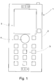
- the control element 6 is located in the place of the keypad part 3 of the device's user interface (compare to Figure 1), essentially below the display part 5 of the device, where it can be operated using a thumb, for example, when holding the device 1 on one's palm between the thumb and the fingers.
- control element 6 according to the invention may naturally be located elsewhere in the cover part 2 of the device.
- Another alternative for the placement of the control element 6 according to the invention is the side cover of the device, where the control element 6 may be operated in a natural manner when holding the device on one's palm (for example, on the side pointed by the arrow in reference 1).
- a third alternative for the placement of the control element 6 according to the invention is the back cover of the device, where the control element 6 may be operated while viewing the display part 5 located in the front cover of the device.
- the control element 6 also comprises a roller element 6c rotating in the plane of the cover part; the roller element may be used for presenting information about the operating mode of the control element 6 (navigation/alphanumeric) to the user. If the control element 6 is in the navigation mode, the display parts 9a on the outer surface of the roller element 6c can be used for presenting the different navigation directions, for example eight directions, so that it will be easier for the user to activate the control component 6b correctly.
- the display parts 9b on the inner perimeter of the roller element 6c can also be used for presenting navigation information to the user, as illustrated in Figure 3a.
- the roller element 6c can also be used by the user for activating the different modes; in this case, the roller element 6c operates as a switch when it is rotated in a plane-like manner against the cover part in the direction pointed by arrow 8, conveying a control signal about the mode change to the control unit of the electronic device. If the control element is in the alphanumeric mode, the alphanumeric characters corresponding to said positions will be presented to the user on the outer surface of the roller element 6c, as illustrated in Figure 3b.
- the distribution of the characters is preferably based on the established key pattern of a mobile phone, where the keypad is implemented in rows of three keys and a number also typically corresponds to a specific control function or an alphanumeric character.
- a possible correspondence mapping is the following: Number key : Alphanumeric character: 1 voicemail service 2 abc 3 def 4 ghi 5 jkl 6 mno 7 pqrs 8 tuv 9 wxyz as illustrated in Figure 3b.
- the roller element 6c also comprises bearing parts (not shown in the figure) for mounting the roller element 6c in the cover part 2 so that the roller element 6c is arranged to move in relation to the cover part 2, and sensor parts (not shown in the figure) for detecting the movement of the roller element 6c and conveying a control signal corresponding to the movement, most suitably an electric signal, to the device 1.
- the control element 6 may also be located in the device 1 on any other surface of the outer cover 2, for example on the back cover or side cover of the device, providing more space in the front cover for larger display means 5.
- Figure 3a illustrates a multi-purpose control element 6 according to a preferred embodiment of the invention presented in a first operating mode.
- the operating mode is the navigation mode, which is activated from the alphanumeric mode by rotating the roller element 6c of the control element 6 clockwise or counter-clockwise in the direction of the arrow 8.
- the bearing parts (not shown in the figure) between the roller element 6c and the cover part 2 can be implemented so that when rotating the roller element 6c, the user feels a step-type resistance and is able to better notice when the position of the roller element 6c changes by one step and the mode is changed.
- a step of rotation in the roller element 6c corresponds to an approximate rotational angle of 22.5 degrees.
- the roller element 6c includes information display parts 9a and 9b for presenting information related to the operating mode of the control element to the user in the different operating modes.
- the display parts 9a located on the outer perimeter of the roller element 6c while in the navigation mode shows the navigation directions (left, right, up, down).
- the user is able to press the appropriate part of the control component 6b depending on the navigation information he wants to convey to the device 1.
- the invention is not restricted to four directions. More precise implementations can be realised by adding intermediate directions.
- the control element 6b also comprises an information display part 9c for presenting information related to the various navigation directions while in the navigation mode, as illustrated in Figure 3a where curve-shaped navigation information elements are shown on the display part 9c in the locations corresponding to the four navigation directions shown on the display part 9b in order to facilitate navigation.
- a possible method of implementing the information display parts is the use of LEDs (Light Emitting Diodes), so that depending on the mode, LEDs with light patterns of a desired shape will be activated to the user through the parts 9a to 9c made of transparent surface material.
- Another alternative for implementation can be that parts of a desired shape made of transparent material are implemented in the roller element 6c or the control component 6b, and LEDs with no specific light patterns are activated below said elements 6b and 6c so that the information corresponding to the transparent opening will be conveyed to the user.
- a third possible method of implementation is to entirely cover the desired elements, such as the roller element 6c and the control component 6b, with display material so that the surfaces of the elements will operate as small display elements and can be used for presenting the desired information to the user depending on the mode.
- the keys 6a illustrated in Figure 3a are not required for actual selection of direction, but they can be used for providing added value to navigation, for example by means of a mouse activation function known from computers.
- the rotation of the roller element 6c can be restricted to two distinct positions, and a tab covering the keypad part 6a can be formed in the lower part of the roller element 6c so that when the device 1 is in the navigation mode, the tab covers the keypad part 6a blocking access to it, and when the device 1 is in the alphanumeric mode, the tab moves away from the keypad part 6a, allowing the user to access the keys.
- the user in the alphanumeric mode, the user has changed the mode by rotating the roller element 6c in either of the directions pointed by the arrow 8.
- the sensor means 18 monitoring the position of the roller element, illustrated later in Figure 6, will convey information about the mode change to the device 1.
- the sensor means 18 will be discussed later in connection with Figure 6.
- the information display parts 9a on the outer perimeter of the roller element 6c show the figures "1-4" and "6-9", as well as the letters and special characters under the figures, as illustrated in Figure 3b.
- the figure '5' is presented using the display part 9c in the control component 6b.
- the figure '0', the characters '*' and '#', as well as a number of other special characters, will be located in the keys corresponding to the characters in the keypad part 6a, and the corresponding information is presented to the user by means of LEDs below the transparent surface of the keypad part 6a in a corresponding manner as described above for parts 9a to 9c.
- numbers and/or characters are entered by pressing the pivoting control component 6b logically at the position on the outer perimeter of the control component 6b corresponding to the desired number or character information shown on the outer perimeter of the roller element 6c.
- the figure '5' and the characters corresponding to it are entered by pressing the control component 6b essentially at the middle.
- the alphanumeric part of the display part 9c on the control component 6b will be activated and the navigation part will be deactivated.
- the figure '5' and the characters "jkl" will appear on the display part 9c, and the curve-shaped navigation information elements visible in the navigation mode will disappear from the view.
- the navigation directions shown on the display part 9b on the inner perimeter of the roller element will be deactivated similarly.
- information can be presented to the user by means of LCD display structures instead of LEDs.
- the user instead of pressing the pivoting control component 6b, the user will press the roller element 6c; the sensor means 18 monitoring the position of the roller element 6c are also arranged to convey information about the location of pressure. The user will press the roller element 6c logically at the position corresponding to the desired navigation direction, number or character information shown on the roller element 6c.
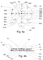
- Figure 4a illustrates the simplified structure of a control element 6 according to a first preferred embodiment of an invention applied to the device viewed from the top.
- the detailed structure of the bearing parts is known as such to the skilled person, for example from the prior art control roller solutions mentioned above, so it is not necessary to describe their operation in more detail in this context.
- the structure of the sensor parts is discussed later in connection with Figures 4b and 5.
- LEDs are used for presenting the information.
- the visibility of various information elements on the control element 6 can be controlled by activating the LEDs.
- the device When the roller element 6c is rotated to the position illustrated in Figure 4a, the device is considered to be in the alphanumeric mode, and the LEDs 42a-h on the outer perimeter of the roller element 6c, the LED 41e on the control component and the LEDs 43a-c on the keypad part will be activated.
- said LEDs 42a-h, 41e and 43a-c pertaining to the alphanumeric mode will be deactivated (turned off), and the LEDs 40a-d and 41a-d required in the navigation mode will be activated (turned on).
- the figure also illustrates the joystick element 44 located below the control component 6b when viewed from the top.
- the joystick element is used for sensing the movement of the control component. Because of the joystick element 44, the LED 41e in the control component 6b is located slightly off-centre on the control component 6b. In Figure 4a, to make the placement of the LEDs more clear, the LEDs are shown as if they were located on the surface of the control element 6, even though they are actually located below the control element 6 and only the light pattern activated by the LEDs is shown to the user. Figure 4a also illustrates the elements 44a-b that provide information about the the position of the roller element 6c; in an embodiment of the invention, these elements are light-sensitive LEDs.
- the LED 44a When the roller element 6c, which is opaque to light, covers the light-sensitive LED 44a, as illustrated in Figure 4a, the LED 44a will convey a control signal corresponding to the "closed” state to the device. When the light-sensitive LED is not covered by the roller element 6c, as is the case with LED 44b in Figure 4a, the LED 44b will convey a control signal corresponding to the "open” state to the device. On the basis of these "closed/open" control signals, the control unit of the device is able to change the state information presented to the user.
- the position of the roller element 6c may also be determined by means of one light-sensitive LED, but the state can be determined more reliably using two LEDs. Other possible implementations for determining the position include a mechanical switch structure (not shown in the figure) for determining the mode selected by the user.
- a separate button for additional functions may be arranged at the centre of the control component 6b in the control element 6.
- said button may function as an activation button for activating a specific function or moving forward/backward in the menu structure.
- said button in the alphanumeric mode, said button may function as the number key '5'.
- Figure 4b illustrates the simplified structure of a control element 6 according to a first preferred embodiment of an invention applied to the device viewed from the side.
- the LEDs 40a-d, 41a-d, 42a-h and 43a-c (not shown in the figure) are installed on the printed circuit board 45 of the device. Said LEDs are activated on the basis of control signals from light-sensitive LEDs 44a-b determining the position of the roller element 6c.
- the layer 46 generating the light pattern seen by the user is located above the LEDs.
- the layer contains character patterns made of transparent material, by means of which the light from the LEDs below will reflect the desired character to the user.
- An alternative implementation is to use transparent material for other parts of the layer 46 and opaque material for the character patterns only.
- the display parts 9a-c discussed above in connection with Figures 3a and 3b are formed from the layer 46.
- the movements of the control component 6b in the various operating modes are sensed using the joystick element 44.
- the joystick is fastened to the control component 6b and will convert the user's activation of the control component 6b in a specific direction into an electric control signal that will be conveyed to the control unit of the device.
- the joystick element 44 is able to differentiate between the eight directions required by the invention and a button press function corresponding to the figure '5' in the alphanumeric mode, for example.
- the joystick element 44 may be located in the layer 46 or on the printed circuit board 45 of the device. As the element is known as such from prior art, it is not necessary to describe it in any more detail in this context.
- Figure 5 illustrates the simplified structure of a control element 6 according to a second preferred embodiment of an invention applied to the device viewed from the side.
- pressure on the control component 6b is sensed using the key membrane 51 and the key caps 50 instead of using the joystick structure described above.
- Key caps 45 corresponding to the activation spots of the control component 6b are implemented on the printed circuit board 45 of the device.
- the key membrane 51 below the control component 51 conveys the pressure to the key cap 50; as the key cap moves down, it makes an electrical contact with a switch element on the surface of the printed circuit board 45, and information about the user's pressing action is conveyed to the control unit of the device.
- a similar implementation may be constructed using either the key membrane 51 or the key caps 50 only; in the former case, the surface of the key membrane 51 contacting the printed circuit board 45 will make an electrical contact as such, and in the latter case, the bottom surface of the control component 6b will directly press the key cap 50, causing an electrical contact.
- the number of key caps in the implementation may be reduced by placing the key caps 50 only at the figures '5', '2', '6', '8' and '4' and reading the rest of the numbers as combinations of these, that is, simultaneous activation of two key caps 50; for example, when the figures '6' and '8' are pressed simultaneously, the control unit of the device will get the information that the user has pressed the figure '9'.
- LEDs can be used for determining the position of the roller element 6c, illuminating the control element 6 and presenting keypad information, just as shown in the examples of Figures 4a-b.
- Figure 5 illustrates possible locations for the light-sensitive LED 44b and two LEDs 42f and 42b for showing keypad information.
- FIG. 6 shows a simplified block diagram of the control means 12 ⁇ 20 of a wireless communications device according to a preferred embodiment of the invention.
- the wireless communications device 1 comprises, among other components, a control unit 20, memory means 12, display means 5 and input means 14.
- the input means 14 correspond, for example, to the other keys implemented in the wireless communications device 1 in addition to the control element 6.
- the block diagram also shows audio means 15, such as an earphone 15a and a microphone 15b, as well as an audio block 15c for analog-to-digital conversion of the microphone signal and digital-to-analog conversion of the signal to the earphone 15a, for example.
- the audio means 15 may comprise an additional earphone 15d and an additional microphone 15e, for example for use with different cover parts of the device 1.
- the memory means 7 comprise RAM (Random Access Memory) particularly for storing information required during operation of the device 1, as well as ROM (Read-Only Memory) particularly for storing programs.
- the control unit 20 comprises, for example, a MCU (Microcontroller Unit) and a programmable logic circuit (ASIC, Application Specific Integrated Circuit), and it is also connected to control blocks 19 or similar blocks controlling other functions of the wireless communications device 1, such as the reception and transmission functions, I/O functions and RF sections of the device 1.
- MCU Microcontroller Unit
- ASIC Application Specific Integrated Circuit
- the control unit 20 is also connected to the control element 6, particularly to its sensor means 18, which provide the control unit 20 with the control signal 16.
- the sensor means 18 in a control element 6 comprise the means for sensing user activation of the control component 6b, such as the joystick element 44.
- the joystick is fastened to the control component 6b and will convert the user's activation of the control component 6b in a specific direction into an electric control signal.
- the sensor means 18 may alternatively comprise the key membrane 51 and/or the key caps 50.
- the sensor means 18 in a control element 6 also comprise the light-sensitive LEDs 44a and 44b that sense the movement of the roller element 6c and convert it to an electric control signal 16.
- the sensor means of the roller element 6c may alternatively comprise a roller that is pressed against the roller element 6c and rotates under control of the roller element 6c by means of friction (not shown in the previous figures).
- the control signal 16 preferably comprises information about the activation of the keypad part 6a, control component 6b or roller element 6c in the control element 6, for example.
- the device 1 using the invention may also comprise moving cover parts such as a sliding cover structure, a flap-type structure folding over a hinge or a two-part communicator-type device structure (such as the Nokia 9210 Communicator).
- the device 1 may comprise a separate switch element 17 for conveying information about the position of said moving cover structure to the control unit 20.
- control element 6 can be deactivated on the basis of a signal from the switch element 17 when the device is in the open position and the PDA (Personal Digital Assistant) user interface is used, or some alternative functions for use in the closed position of the device may be defined for the control element 6.
- CMT Cellular Mobile Telephone
- PDA Personal Digital Assistant
- the invention may also be utilised for controlling several functions of the device 1 using different operation sequences of the control element 6.
- the display part 5 may show the effect of the operation sequences and the state of the device 1.
- a key press refers to either a press on a key located in the centre of the control component 6b, a press on the entire control component 6b, or a press on a key in the keypad part 6a.
- a possible implementation of a key press according to the invention is that in addition to rotation, the key press effect is taken into account in the implementation of the roller element 6c. In this case, the user can generate key press/rotation sequences using the roller element only.
- Operation sequences for controlling the device 1 include, for example, a sequence comprising a long key press that will switch the device on (“Power On” state) or off (“Power Off” state), or as the phone is ringing, a sequence of movement to the additional position, clockwise rotation and counter-clockwise rotation for answering the call (“Send” state), or as the phone is ringing or a call is in progress, a sequence of movement to the additional position and clockwise rotation for ending the call (“End” state), or in the normal state of the device 1, a sequence of movement to the additional position and clockwise rotation for locking the keypad, a sequence of movement to the additional position, counter-clockwise rotation and clockwise rotation for switching to the "Menu” state, or a sequence of movement to the additional position and clockwise rotation for switching from the "Menu” state to the normal state (and for going back in the menu structure).
- a PIN code (Personal Identification Number) can be entered into the device 1 by rotating and selecting the numbers by a key press, or in alphanumeric mode by pressing particular points of the control component, but also in a manner where the PIN code constitutes a specific operation sequence.
- the operation sequences can be defined by the user and stored in the device 1, for example using a separate function.
- the device 1 contains one or more operation sequences comprising at least one movement of the roller element 6c and at least one other movement of the control element 6 essentially following in immediate sequence.
- An example of an operation sequence is clockwise rotation followed by counter-clockwise rotation.
- the roller element 6c may be implemented so that it will automatically return to its normal position, for example by spring action, when the roller element 6c is not touched. The movements follow each other in essentially immediate sequence. Timers in the control unit of the device 1 and preset time limits are used for monitoring the performance of the sequences.
- a spring-operated roller element 6c for selecting the operating modes may be implemented so that the control unit 20 of the device 1 will monitor the control signal from the sensor means 18, such as the light-sensitive LEDs 44a-b, sensing the position of the roller element 6c, and will change the operating mode in accordance with the control signal even though the spring will always return the roller element 6c to its normal state.
- the control element 6 is operated so that by holding a key in the keypad part 6a or the control component 6b in the down position, that is, the moved position, and simultaneously rotating the roller element 6c from its normal position, the menu structure of the device 1 can be navigated down and up.
- said key press on the keypad part 6a or the control component 6b in the context of sequence generation or menu structure navigation is referred to as a sequence key press.
- releasing refers particularly to returning the control element 6 to its normal position.
- the use of the control element 6 can be simplified and the number of operating errors can be reduced by arranging the roller element 6c to be automatically releasing, for example by means of spring action.
- the device 1 may be switched on by holding the control component 6b in the down position so that the device 1 switches into a state where the switching on can be confirmed. After this, the device 1 switches into a state where information constituting the basic menu functions and, as additional information, the identifier of the telephone network provider is shown on the display.
- the sequence key press is held active.
- the cursor on the display 5 will activate and show the current menu function by means of highlighting, for example.
- the sequence key press is held active, the cursor will move from a menu function to another by rotating the roller element 6c and will show the available menu functions.
- the display 5 will next show information comprising both basic level menu functions and a menu function on the next level, such as the "Phone Settings" menu function.
- the basic level menu functions can now be accessed by making a sequence key press and holding it active, which will return the device to the initial state or show the basic level menu functions on the display in addition to the "Phone Settings" menu function.
- the menu structure may alternatively be navigated backwards by holding the sequence key press active and rotating the roller element 6c, which may change the "Ringing Volume” menu function, for example, first to the "Phone Settings” menu function and further to the basic level.
- the menu structure may be navigated forward, returning on the route used for the "Ringing Volume” menu function; the route is also stored in the memory of the device.
- the route may be navigated backwards and forwards by means of a single control element 6 and a single grip on the device. Naturally, the navigation back to a higher level may only be arranged up to the menu function previously reached by making selections on the route.
- the "Backlights on/off” menu function can be accessed in the previous case by navigating to the "Phone Settings” menu function by means of rotation in the additional position and by releasing the control element 6.
- the "Ringing Volume” and “Backlights on/off” menu functions can be browsed on the display by means of rotation, and the "Backlights on/off” menu function can be selected by means of a sequence key press.
- the display may show the alternatives "ON” and "OFF”, with a flashing cursor, for example, indicating the current selection.
- the period of time used for holding the sequence key press active may also be used for differentiating between functions of the device 1; in this case, for example when the key is pressed, the device 1 will wait for rotation for a moment and only after a preset period of time will automatically return to the basic level. This allows the user to indicate the desired function to the device 1 by means of the duration of the key press or the duration of the key press before rotation.
- the control unit 20 of the device 1 will monitor the delays in the actions and the operation sequences of the control elements by means of timers, for example. On the basis of the signal 16 received from the sensor means 18, a control program operating under the control unit 20 will control the display part in order to present information. Information about the states, menu structure and menu functions of the device 1 is stored in the device 1, and on the basis of control signals received from the control element 6, the control program will select the information to be presented and will control the other operations of the device.
- the appropriate menu function can be accessed as described in the following. While holding the sequence key press active, the roller element 6c is rotated to access the "Backlights on/off" menu function. The return will also indicate to the control unit of the device 1 that the function is cancelled.
- the roller element may be rotated clockwise or counter-clockwise.
- the desired menu function can be accessed by continuing to hold the sequence key press and rotating the roller element.
- the horizontal level with the "Phone Settings" menu function is selected by releasing the control element 6.
- the menu functions on this level may now be browsed by rotating the roller element, and the desired "Power Off(/On)" menu function can be selected by clicking the control component 6b.
- the device 1 may request confirmation for the power off function, which may also be confirmed by clicking.
- control element 6 in a mode of the device 1 used for forming a string of alphanumeric characters.
- the control element of the device illustrated in Figure 2 is switched to the alphanumeric entry mode by rotating the roller element 6c.
- a possible method of implementing the mode is that when the roller element 6c is rotated once either clockwise or counter-clockwise, the operating mode of the device will change from the navigation mode to the "123" submode of the alphanumeric entry mode, where the user can enter numbers from 1 to 9 using the control component 6b.
- Another rotation of the roller element in the same direction will switch the device to the "abc" mode where the user can enter lowercase letters from a to z using the control component 6b.
- a third rotation of the roller element 6c will switch the device back to the "123" mode, and a fourth rotation of the roller element 6c in the same direction will switch the device to the "ABC" mode where the user can enter uppercase letters from A to Z using the control component 6b.
- the invention may also be applied to other operating modes of the device, and the sequence for switching from one mode to another is not restricted to those described above but may vary within the scope of the independent claims.
- the locking functions of the device 1 will be examined. While the device 1 is locked, the display may show information pertaining to the locked state. In this state, the keypad part 6a or the other control element 6 cannot be used, and only a select set of functions is available in the device 1.
- the device can be locked by browsing to the appropriate menu function and selecting it.
- Another alternative for activating the locking function according to the invention is to define a specific control element sequence which may include the use of the various parts of the control element 6, the keypad part 6a, the control component 6b and the roller element 6c. A possible sequence might be one clockwise rotation followed by one counter-clockwise rotation of the roller element and a press on the control component within a set time limit, for example 3 seconds.
- the lock can be opened, for example, by means of a similar sequence using the various parts of the control element 6, or the appropriate unlock function can be accessed in the menu of the device using the control element 6.
- an incoming call may automatically initiate a mode where the "Answer" menu function for answering the call or the "Hangup” menu function can be selected. Browsing of the functions may be implemented by rotating the roller element 6c or pressing the control component 6b, and the desired function may be selected either by pressing the control component 6b or the keypad part 6a.
- the volume of the speaker 15d or 15a in the device 1 may be adjusted by rotating the roller element 6c or pressing the control component 6b of the control element 6, and the call may be terminated by clicking the control component 6b or the keypad part 6a.
- the present invention has several advantages in comparison with prior art implementations.
- the invention can be applied, for example, to mobile phones, palmtop computers and small laptop computers.
- it can be used in electronic games and the user interfaces of home and office electronic devices such as hifi equipment or car stereos, as well as in multimedia devices used on aircraft, for example.
Landscapes
- Engineering & Computer Science (AREA)
- General Engineering & Computer Science (AREA)
- Theoretical Computer Science (AREA)
- Human Computer Interaction (AREA)
- Physics & Mathematics (AREA)
- General Physics & Mathematics (AREA)
- Computer Networks & Wireless Communication (AREA)
- Signal Processing (AREA)
- Input From Keyboards Or The Like (AREA)
- Telephone Set Structure (AREA)
- Selective Calling Equipment (AREA)
Abstract
Description
a control element for receiving input from the user; said control element comprises at least a first input means and a second input means,
a protective cover with a specified place for the control element, characterised in that
the first input means is a multi-function input means and the second input means is essentially a ring-shaped input means rotatable in a plane, and
said control element has a first input mode and a second input mode; in the first input mode, the control element is arranged to provide the device with navigation information in response to at least one of the following actions:
- operation of the first input means
- operation of the second input means; and
- operation of the first input means
- operation of the second input means.
a control element is used in the electronic device for providing input; the control element comprises at least a first input means and a second input means,
characterised in that to use the device,
the first, multi-function, input means is activated and
the second, essentially ring-shaped, input means is rotated in a plane, and that
the control element is arranged to operate in a first input mode where the device is provided with navigation information in response to at least one of the following actions:
- operation of the first input means
- operation of the second input means, and
- operation of the first input means
- operation of the second input means.
characterised in that
the first input means is a multi-function input means and the second input means is essentially a ring-shaped input means rotatable in a plane, and
said control element has a first input mode and a second input mode; in the first input mode, the control element is arranged to receive input in the form of navigation information; and
in the second input mode, the control element is arranged to receive input in the form of alphanumeric information.
| Number key: | Alphanumeric character: |
| 1 | |
| 2 | |
| 3 | |
| 4 | |
| 5 | jkl |
| 6 | mno |
| 7 | |
| 8 | |
| 9 | wxyz |
Claims (14)
- An electronic device (1) comprising:characterised in thata control element (6) for receiving input from the user; the control element (6) comprises at least a first input means (6b) and a second input means (6c),a protective cover (2) with a specified place for the control element (6),
the first input means (6b) is a multi-function input means and the second input means (6c) is essentially a ring-shaped input means rotatable in a plane, and
said control element (6) has a first input mode and a second input mode; in the first input mode, the control element (6) is arranged to provide the device with navigation information in response to at least one of the following actions:in the second input mode, the control element (6) is arranged to provide the device with alphanumeric information in response to at least one of the following actions:operation of the first input meansoperation of the second input means; andwherein the control element is configured to provide the device with particular alphanumeric information in response to the press on a particular location.a press on a particular location of the first input means out of several possible press locations,a press on a particular location of the second input means out of several possible press locations - An electronic device (1) according to claim 1,
characterised in that
in the first input mode, the control element (6) is arranged to provide the device with navigation information in response to at least one of the following actions:wherein the control element is configured to perform a particular navigation function in response to the press on a particular location.a press on a particular location of the first input means out of several possible press locations,a press on a particular location of the second input means out of several possible press locations - An electronic device (1) according to claim 1,
characterised in that
in the first input mode, the control element (6) is arranged to perform a particular navigation function in response to
either holding the second ring-shaped input means pressed towards either a clockwise or counterclockwise direction or scrolling the second ring-shaped input means towards either a clockwise or counterclockwise direction, and
releasing the second ring-shaped input means. - An electronic device (1) according to claim 1,
characterised in that
in addition, the control element (6) comprises a third input means (6a) formed of one or more keys. - An electronic device (1) according to claim 1 or 4,
characterised in that
the first input means (6b) is arranged to receive input information from the user, and
the second input means (6c) is arranged to receive mode switch information from the user for switching between the first and the second input modes. - An electronic device (1) according to claim 1 or 4,
characterised in that
the third input means (6a) is arranged to receive input information from the user, and
the second input means (6c) is arranged to receive mode switch information from the user for switching between the first and the second input modes. - An electronic device (1) according to claim 1,
characterised in that
the first, multi-function, input means (6b) is arranged to receive presses, touches or movements from the user. - An electronic device (1) according to claim 4,
characterised in that
the first input means (6b) is located on the protective cover (2) of the device inside the ring-shaped second input means (6a), and
the third input means (6a) is located on the protective cover (2) of the device below the second input means (6c). - An electronic device (1) according to claim 1,
characterised in that
the control element (6) comprises means (40a-d, 41a-e, 42a-h) for presenting information about the input mode to the user. - A device (1) according to claim 1,
characterised in that
in the first mode, the information presented by said means (40a-d, 41a-e, 42a-h) comprises the navigation directions selectable by means of the control element (6), and
in the second mode, the information presented by said means (40a-d, 41a-e, 42a-h) comprises the alphanumeric characters selectable by means of the control element (6). - An electronic device (1) according to any one of the preceding claims,
characterised in that
the device (1) is arranged to be controlled using one or more operation sequences of the control element (6), the operation sequence consisting of a set of first movements and second movements essentially in immediate sequence. - An electronic device (1) according to claim 11,
characterised in that
said first movements are movements of the first, multi-function, input means (6b), and
said second movements are movements of the second input means (6c), rotatable in a plane. - A method for using an electronic device, which method comprises in the electronic device (1), a control element (6) is used for entering input; the control element (6) comprises at least a first input means (6b) and a second input means (6c),
characterised in that to use the device
the first, multi-function, input means (6b) is activated, and
the second, essentially ring-shaped, input means (6c) is rotated in a plane, and that
the control element (6) is arranged to operate in a first input mode where the device is provided with navigation information in response to at least one of the following actions:the control element (6) is arranged to operate in a second input mode where the device is provided with alphanumeric information in response to at least one of the following actions:operation of the first input means (6b)operation of the second input means (6c), andoperation of the first input means (6b)operation of the second input means (6c). - A control element (6) for an electronic device, the device (1) comprising at least one protective cover (2) for adapting the control element (6) and the control element (6) comprising at least a first input means (6b) and a second input means (6c),
characterised in that
the first input means (6b) is a multi-function input means and the second input means (6c) is essentially a ring-shaped input means rotatable in a plane, and
said control element (6) has a first input mode and a second input mode; in the first input mode, the control element (6) is arranged to receive input in the form of navigation information; and
in the second input mode, the control element (6) is arranged to receive input in the form of alphanumeric information.
Applications Claiming Priority (2)
| Application Number | Priority Date | Filing Date | Title |
|---|---|---|---|
| FI20012610 | 2001-12-31 | ||
| FI20012610A FI20012610L (en) | 2001-12-31 | 2001-12-31 | Electronic device and control element |
Publications (2)
| Publication Number | Publication Date |
|---|---|
| EP1333363A2 true EP1333363A2 (en) | 2003-08-06 |
| EP1333363A3 EP1333363A3 (en) | 2009-09-16 |
Family
ID=8562613
Family Applications (1)
| Application Number | Title | Priority Date | Filing Date |
|---|---|---|---|
| EP02396184A Withdrawn EP1333363A3 (en) | 2001-12-31 | 2002-12-12 | Electronic device and control element |
Country Status (4)
| Country | Link |
|---|---|
| US (1) | US7170497B2 (en) |
| EP (1) | EP1333363A3 (en) |
| CN (1) | CN100478850C (en) |
| FI (1) | FI20012610L (en) |
Cited By (2)
| Publication number | Priority date | Publication date | Assignee | Title |
|---|---|---|---|---|
| EP1467542A1 (en) * | 2003-04-10 | 2004-10-13 | Sony Ericsson Mobile Communications AB | Portable electronic equipment having a light indicator |
| EP1542437A3 (en) * | 2003-12-12 | 2005-12-07 | Samsung Electronics Co., Ltd. | Mobile communication terminal with multi-input device and method of using the same |
Families Citing this family (62)
| Publication number | Priority date | Publication date | Assignee | Title |
|---|---|---|---|---|
| US7312785B2 (en) | 2001-10-22 | 2007-12-25 | Apple Inc. | Method and apparatus for accelerated scrolling |
| US7333092B2 (en) | 2002-02-25 | 2008-02-19 | Apple Computer, Inc. | Touch pad for handheld device |
| WO2004075004A2 (en) * | 2003-02-14 | 2004-09-02 | Mattel, Inc. | Hand-held interactive electronic device |
| US20040253989A1 (en) * | 2003-06-12 | 2004-12-16 | Tupler Amy M. | Radio communication device having a navigational wheel |
| US7499040B2 (en) | 2003-08-18 | 2009-03-03 | Apple Inc. | Movable touch pad with added functionality |
| US20070152977A1 (en) | 2005-12-30 | 2007-07-05 | Apple Computer, Inc. | Illuminated touchpad |
| AU2003273411A1 (en) * | 2003-09-30 | 2004-09-30 | Siemens Aktiengesellschaft | Input device; means and methods for predicting text input; and mobile terminal |
| US8059099B2 (en) | 2006-06-02 | 2011-11-15 | Apple Inc. | Techniques for interactive input to portable electronic devices |
| US7495659B2 (en) | 2003-11-25 | 2009-02-24 | Apple Inc. | Touch pad for handheld device |
| EP1538513A1 (en) * | 2003-12-02 | 2005-06-08 | Sony Ericsson Mobile Communications AB | User interface |
| USD513737S1 (en) * | 2004-01-13 | 2006-01-24 | Harry Lee Riley | Controller |
| USD515038S1 (en) * | 2004-01-13 | 2006-02-14 | Harry Lee Riley | Controller |
| KR100927064B1 (en) | 2004-08-16 | 2009-11-13 | 애플 인크. | A method of increasing the spatial resolution of touch sensitive devices |
| US7362312B2 (en) * | 2004-11-01 | 2008-04-22 | Nokia Corporation | Mobile communication terminal and method |
| US20060271886A1 (en) * | 2005-05-25 | 2006-11-30 | Wenstrand John S | Character entry system and method for electronic devices |
| KR100538572B1 (en) * | 2005-06-14 | 2005-12-23 | (주)멜파스 | Apparatus for controlling digital device based on touch input interface capable of visual input feedback and method for the same |
| US7720829B2 (en) * | 2005-07-14 | 2010-05-18 | International Business Machines Corporation | Middleware sign-on |
| US7880729B2 (en) | 2005-10-11 | 2011-02-01 | Apple Inc. | Center button isolation ring |
| US20090085875A1 (en) * | 2005-11-14 | 2009-04-02 | Shigeyuki Inoue | Input device |
| US20070152983A1 (en) | 2005-12-30 | 2007-07-05 | Apple Computer, Inc. | Touch pad with symbols based on mode |
| USD549184S1 (en) | 2006-01-23 | 2007-08-21 | Bachmann Industries, Inc. | Controller |
| USD549181S1 (en) | 2006-02-13 | 2007-08-21 | Bachmann Industries, Inc. | Controller |
| KR100754674B1 (en) * | 2006-03-10 | 2007-09-03 | 삼성전자주식회사 | Method and device for selecting menu in mobile terminal |
| USD560681S1 (en) * | 2006-03-31 | 2008-01-29 | Microsoft Corporation | Icon for a portion of a display screen |
| KR101176943B1 (en) * | 2006-05-09 | 2012-08-30 | 삼성전자주식회사 | A function key assembly for fortable device |
| US8079766B2 (en) * | 2006-06-09 | 2011-12-20 | Marty Forrest Kinney | Key input system and device incorporating same |
| US8022935B2 (en) | 2006-07-06 | 2011-09-20 | Apple Inc. | Capacitance sensing electrode with integrated I/O mechanism |
| US9360967B2 (en) | 2006-07-06 | 2016-06-07 | Apple Inc. | Mutual capacitance touch sensing device |
| US8743060B2 (en) | 2006-07-06 | 2014-06-03 | Apple Inc. | Mutual capacitance touch sensing device |
| US8057116B1 (en) * | 2006-08-10 | 2011-11-15 | Nextel Communications Inc. | Data input mechanism |
| US7795553B2 (en) * | 2006-09-11 | 2010-09-14 | Apple Inc. | Hybrid button |
| US8274479B2 (en) | 2006-10-11 | 2012-09-25 | Apple Inc. | Gimballed scroll wheel |
| US8482530B2 (en) | 2006-11-13 | 2013-07-09 | Apple Inc. | Method of capacitively sensing finger position |
| EP1959238B1 (en) * | 2007-02-13 | 2018-05-23 | Harman Becker Automotive Systems GmbH | Method for inputting a destination in a navigation unit and nagivation system therefor |
| DE102007050177B4 (en) * | 2007-06-12 | 2012-04-12 | Lg Electronics Inc. | Input device, with such a equipped mobile terminal and user interface thereof |
| KR101356158B1 (en) * | 2007-06-12 | 2014-01-24 | 엘지전자 주식회사 | Input device and mobile terminal having the same |
| US7873906B2 (en) | 2007-06-22 | 2011-01-18 | International Business Machines Corporation | Method and system for presenting a visual notification and delaying an action responsive to an onscreen selection |
| KR100857254B1 (en) * | 2007-08-02 | 2008-09-05 | 주식회사 로직플랜트 | Display control method, terminal using the method and recording medium recording the method |
| CN201315050Y (en) | 2007-09-04 | 2009-09-23 | 苹果公司 | Compact input device |
| US8683378B2 (en) | 2007-09-04 | 2014-03-25 | Apple Inc. | Scrolling techniques for user interfaces |
| US8416198B2 (en) | 2007-12-03 | 2013-04-09 | Apple Inc. | Multi-dimensional scroll wheel |
| US20090158345A1 (en) * | 2007-12-17 | 2009-06-18 | Peter Mortensen | Television user mode |
| KR20090065000A (en) | 2007-12-17 | 2009-06-22 | 삼성전자주식회사 | Input panel device, image forming device using same and method thereof |
| KR20090065003A (en) * | 2007-12-17 | 2009-06-22 | 삼성전자주식회사 | Input device suitable for task flow and image forming device using same |
| US8125461B2 (en) | 2008-01-11 | 2012-02-28 | Apple Inc. | Dynamic input graphic display |
| US8820133B2 (en) | 2008-02-01 | 2014-09-02 | Apple Inc. | Co-extruded materials and methods |
| US9454256B2 (en) | 2008-03-14 | 2016-09-27 | Apple Inc. | Sensor configurations of an input device that are switchable based on mode |
| US20100052951A1 (en) * | 2008-09-02 | 2010-03-04 | Burrell Iv James W | Nine sensor data entry keyboard and control means |
| US8816967B2 (en) | 2008-09-25 | 2014-08-26 | Apple Inc. | Capacitive sensor having electrodes arranged on the substrate and the flex circuit |
| US8395590B2 (en) | 2008-12-17 | 2013-03-12 | Apple Inc. | Integrated contact switch and touch sensor elements |
| US9354751B2 (en) | 2009-05-15 | 2016-05-31 | Apple Inc. | Input device with optimized capacitive sensing |
| US8872771B2 (en) | 2009-07-07 | 2014-10-28 | Apple Inc. | Touch sensing device having conductive nodes |
| US20110283241A1 (en) * | 2010-05-14 | 2011-11-17 | Google Inc. | Touch Gesture Actions From A Device's Lock Screen |
| US9013398B2 (en) | 2010-10-19 | 2015-04-21 | Elan Microelectronics Corporation | Control methods for a multi-function controller |
| TWI451293B (en) * | 2010-10-19 | 2014-09-01 | Elan Microelectronics Corp | Control method of multi - function controller |
| US9158457B2 (en) * | 2011-11-17 | 2015-10-13 | International Business Machines Corporation | Adjustment of multiple user input parameters |
| DE202011052043U1 (en) * | 2011-11-21 | 2012-02-09 | Leister Technologies Ag | Hot air hand-held device with a digital operating device with universal operating element |
| CN104854959A (en) * | 2012-12-14 | 2015-08-19 | 郑相民 | Dimming control device and method |
| DE202014105749U1 (en) * | 2014-11-27 | 2015-01-09 | iCradle GmbH | Thumb switch for attachment to a bicycle handlebar and operated via such a thumb switch control system for a bicycle |
| KR20160123879A (en) * | 2015-04-17 | 2016-10-26 | 삼성전자주식회사 | Electronic apparatus and method for displaying screen thereof |
| JP7146762B2 (en) * | 2016-12-15 | 2022-10-04 | ウォーター ピック インコーポレイテッド | Oral irrigator with magnetic attachment |
| CN106843573A (en) * | 2017-01-03 | 2017-06-13 | 惠州Tcl移动通信有限公司 | The mobile terminal and its function of side key implementation method of a kind of side switch virtualization |
Family Cites Families (19)
| Publication number | Priority date | Publication date | Assignee | Title |
|---|---|---|---|---|
| FI87871C (en) | 1990-06-26 | 1995-05-16 | Nokia Mobile Phones Ltd | Device for searching menus in a telephone device |
| US5191320A (en) * | 1990-12-15 | 1993-03-02 | Sony Corporation Of America | Variable scale input device |
| JP3268467B2 (en) * | 1992-09-08 | 2002-03-25 | 株式会社日立製作所 | Telephone |
| US5706448A (en) * | 1992-12-18 | 1998-01-06 | International Business Machines Corporation | Method and system for manipulating data through a graphic user interface within a data processing system |
| CA2159138A1 (en) | 1994-11-28 | 1996-05-29 | Sonia Mercedes Estevez-Alcolado De Holl | Roller bar menu access system and method for cellular telephones |
| US5670955A (en) * | 1995-01-31 | 1997-09-23 | Microsoft Corporation | Method and apparatus for generating directional and force vector in an input device |
| KR200153815Y1 (en) * | 1995-03-31 | 1999-08-02 | 전주범 | Shuttle switch assembly |
| JP3508961B2 (en) | 1995-07-21 | 2004-03-22 | ソニー株式会社 | Terminal device |
| NO301040B1 (en) * | 1995-12-04 | 1997-09-01 | Ziad Badarneh | Keyboards for phones and the like |
| US5808602A (en) * | 1996-03-15 | 1998-09-15 | Compaq Computer Corporation | Rotary cursor positioning apparatus |
| US6173194B1 (en) | 1996-04-15 | 2001-01-09 | Nokia Mobile Phones Limited | Mobile terminal having improved user interface |
| US6636197B1 (en) * | 1996-11-26 | 2003-10-21 | Immersion Corporation | Haptic feedback effects for control, knobs and other interface devices |
| US6034688A (en) * | 1997-09-15 | 2000-03-07 | Sony Corporation | Scrolling navigational display system |
| DE19743283C5 (en) * | 1997-09-30 | 2004-05-27 | Siemens Ag | Multifunctional control unit for communication terminals |
| TW509845B (en) * | 1997-12-13 | 2002-11-11 | Samsung Electronics Co Ltd | Computer system with jog dial function and the user interface scheme thereof |
| NO994723L (en) * | 1998-12-09 | 2000-06-13 | Ziad Badarneh | Keyboard device |
| GB2355144B (en) | 1999-10-08 | 2004-01-14 | Nokia Mobile Phones Ltd | A portable device |
| NO20004375L (en) * | 1999-12-06 | 2001-06-07 | Ziad Badarneh | System and method for displaying and assisting manipulation movements in operating a control device lined with functional equipment |
| US20010048425A1 (en) * | 2000-04-28 | 2001-12-06 | Partridge Gary R. | Device or component for alphanumeric and direction input |
-
2001
- 2001-12-31 FI FI20012610A patent/FI20012610L/en not_active IP Right Cessation
-
2002
- 2002-12-12 EP EP02396184A patent/EP1333363A3/en not_active Withdrawn
- 2002-12-18 US US10/322,147 patent/US7170497B2/en not_active Expired - Fee Related
- 2002-12-30 CN CNB021605343A patent/CN100478850C/en not_active Expired - Fee Related
Cited By (4)
| Publication number | Priority date | Publication date | Assignee | Title |
|---|---|---|---|---|
| EP1467542A1 (en) * | 2003-04-10 | 2004-10-13 | Sony Ericsson Mobile Communications AB | Portable electronic equipment having a light indicator |
| EP1542437A3 (en) * | 2003-12-12 | 2005-12-07 | Samsung Electronics Co., Ltd. | Mobile communication terminal with multi-input device and method of using the same |
| EP1788789A3 (en) * | 2003-12-12 | 2007-05-30 | Samsung Electronics Co., Ltd. | Mobile communication terminal with multi-input device and method of using the same |
| US7397467B2 (en) | 2003-12-12 | 2008-07-08 | Samsung Electronics Co., Ltd. | Mobile communication terminal with multi-input device and method of using the same |
Also Published As
| Publication number | Publication date |
|---|---|
| FI20012610A7 (en) | 2003-07-01 |
| US20030135292A1 (en) | 2003-07-17 |
| FI20012610L (en) | 2003-07-01 |
| CN100478850C (en) | 2009-04-15 |
| FI20012610A0 (en) | 2001-12-31 |
| EP1333363A3 (en) | 2009-09-16 |
| CN1430448A (en) | 2003-07-16 |
| US7170497B2 (en) | 2007-01-30 |
Similar Documents
| Publication | Publication Date | Title |
|---|---|---|
| US7170497B2 (en) | Electronic device and control element | |
| US6487396B1 (en) | Electronic device and a control means | |
| US6968508B2 (en) | Rotating user interface | |
| US8032185B2 (en) | Operation mode conversion device, mobile communication terminal having the operation mode conversion device and method for converting operation mode using the same | |
| EP2367094B1 (en) | Touch sensitive keypad with tactile feedback | |
| US6526296B1 (en) | Electronic device and a control means | |
| US20050125570A1 (en) | Portable communication devices | |
| EP1832095B1 (en) | A mobile terminal, and associated methods, with improved user interface | |
| US20050124387A1 (en) | Portable apparatus user interface | |
| US20030001816A1 (en) | Display and manoeuvring system and method | |
| US20090146959A1 (en) | Input Device for a Portable Terminal | |
| JPH11168540A (en) | Portable telephone set provided with navigation key for handset | |
| US20080291162A1 (en) | Track wheel with reduced space requirements | |
| JP2001069223A (en) | Communication equipment | |
| US20020044155A1 (en) | Portable communication device for a wireless communication system | |
| US20080163129A1 (en) | On-screen cursor navigation delimiting on a handheld communication device | |
| EP1524587A1 (en) | Device having a joystick keypad | |
| US20070123320A1 (en) | Key input device for portable terminal | |
| KR100765218B1 (en) | Input devices for electronic devices requiring input and output of letters, numbers, and symbols | |
| CA2635125C (en) | Appearance adaptable keypad for a handheld communication device | |
| CN1322778C (en) | Method for controlling portable radio communication equipment | |
| KR200369021Y1 (en) | a Mobile Communication Terminal Inputtable a Pointer | |
| CA2572665C (en) | On-screen cursor navigation delimiting on a handheld communication device | |
| KR20060019440A (en) | Mobile communication terminal capable of pointer input and its operation method | |
| EP1538513A1 (en) | User interface |
Legal Events
| Date | Code | Title | Description |
|---|---|---|---|
| PUAI | Public reference made under article 153(3) epc to a published international application that has entered the european phase |
Free format text: ORIGINAL CODE: 0009012 |
|
| AK | Designated contracting states |
Designated state(s): AT BE BG CH CY CZ DE DK EE ES FI FR GB GR IE IT LI LU MC NL PT SE SI SK TR |
|
| AX | Request for extension of the european patent |
Extension state: AL LT LV MK RO |
|
| PUAL | Search report despatched |
Free format text: ORIGINAL CODE: 0009013 |
|
| AK | Designated contracting states |
Kind code of ref document: A3 Designated state(s): AT BE BG CH CY CZ DE DK EE ES FI FR GB GR IE IT LI LU MC NL PT SE SI SK TR |
|
| AX | Request for extension of the european patent |
Extension state: AL LT LV MK RO |
|
| 17P | Request for examination filed |
Effective date: 20100303 |
|
| AKX | Designation fees paid |
Designated state(s): AT BE BG CH CY CZ DE DK EE ES FI FR GB GR IE IT LI LU MC NL PT SE SI SK TR |
|
| 17Q | First examination report despatched |
Effective date: 20100503 |
|
| STAA | Information on the status of an ep patent application or granted ep patent |
Free format text: STATUS: THE APPLICATION IS DEEMED TO BE WITHDRAWN |
|
| 18D | Application deemed to be withdrawn |
Effective date: 20100914 |