EP1333334A1 - Document feeder and image forming apparatus - Google Patents
Document feeder and image forming apparatus Download PDFInfo
- Publication number
- EP1333334A1 EP1333334A1 EP03250095A EP03250095A EP1333334A1 EP 1333334 A1 EP1333334 A1 EP 1333334A1 EP 03250095 A EP03250095 A EP 03250095A EP 03250095 A EP03250095 A EP 03250095A EP 1333334 A1 EP1333334 A1 EP 1333334A1
- Authority
- EP
- European Patent Office
- Prior art keywords
- document
- convey
- reading
- section
- guide member
- Prior art date
- Legal status (The legal status is an assumption and is not a legal conclusion. Google has not performed a legal analysis and makes no representation as to the accuracy of the status listed.)
- Granted
Links
- 239000011521 glass Substances 0.000 claims description 17
- 230000007246 mechanism Effects 0.000 description 7
- 238000011144 upstream manufacturing Methods 0.000 description 6
- 230000002950 deficient Effects 0.000 description 5
- 238000000034 method Methods 0.000 description 5
- 230000008569 process Effects 0.000 description 5
- 239000011347 resin Substances 0.000 description 4
- 229920005989 resin Polymers 0.000 description 4
- 238000012805 post-processing Methods 0.000 description 3
- 230000003449 preventive effect Effects 0.000 description 3
- 238000006243 chemical reaction Methods 0.000 description 2
- 238000012545 processing Methods 0.000 description 2
- 238000003705 background correction Methods 0.000 description 1
- 238000004140 cleaning Methods 0.000 description 1
- 238000012937 correction Methods 0.000 description 1
- 238000011161 development Methods 0.000 description 1
- 230000003287 optical effect Effects 0.000 description 1
- 230000009467 reduction Effects 0.000 description 1
- 230000001105 regulatory effect Effects 0.000 description 1
- 239000004065 semiconductor Substances 0.000 description 1
- 238000000926 separation method Methods 0.000 description 1
- 238000012546 transfer Methods 0.000 description 1
Images



Classifications
-
- G—PHYSICS
- G03—PHOTOGRAPHY; CINEMATOGRAPHY; ANALOGOUS TECHNIQUES USING WAVES OTHER THAN OPTICAL WAVES; ELECTROGRAPHY; HOLOGRAPHY
- G03G—ELECTROGRAPHY; ELECTROPHOTOGRAPHY; MAGNETOGRAPHY
- G03G15/00—Apparatus for electrographic processes using a charge pattern
- G03G15/60—Apparatus which relate to the handling of originals
-
- H—ELECTRICITY
- H04—ELECTRIC COMMUNICATION TECHNIQUE
- H04N—PICTORIAL COMMUNICATION, e.g. TELEVISION
- H04N1/00—Scanning, transmission or reproduction of documents or the like, e.g. facsimile transmission; Details thereof
- H04N1/00567—Handling of original or reproduction media, e.g. cutting, separating, stacking
- H04N1/0057—Conveying sheets before or after scanning
Definitions
- the present invention relates to a document feeder which can convey a document and enable image reading in order to form an image with an image forming apparatus such as an electrophotographic copying machine, a printer, a facsimile apparatus, a multifunctional machine having a plurality of these functions, or a printing machine, and an image forming apparatus.
- an image forming apparatus such as an electrophotographic copying machine, a printer, a facsimile apparatus, a multifunctional machine having a plurality of these functions, or a printing machine, and an image forming apparatus.
- documents placed on the sheet feed tray are separated one by one and conveyed by a document convey section.
- the documents can then be read by a reading section.
- a slit glass plate 101 is arranged in a reading section 100.
- a reading guide member 102 is arranged at a position opposing the slit glass plate 101.
- a convey path is formed by a distance 103 between the slit glass plate 101 and reading guide member 102. A document conveyed through this convey path is read.
- the present invention has been made in order to solve the above inconvenience, and has as its object to provide a document feeder which suppresses flapping of a document in a convey path so that a defective image can be prevented from being formed by fluctuations in convey speed, and an image forming apparatus.
- the present invention has the following aspects.
- a document feeder which conveys a document with a document feeding section and reads the document at a reading section, comprising a flexible member with which the document is always conveyed along a convey path without deviation.
- the document is always conveyed along the convey path. Flapping of the document is suppressed, and fluctuations in convey speed can be reduced with a simple arrangement, so that a defective image can be prevented.
- the flexible member is attached to close the convey path.
- the flexible member is a PET sheet.
- the flexible member is a PET sheet, so the cost is low.
- an image forming apparatus comprising a document feeder according to any one of the first to third aspects.
- the image forming apparatus comprises a document feeder according to any one of the first to third aspects, which suppresses flapping of a document in a convey path, so that a defective image can be prevented from being formed by fluctuations in convey speed.
- Fig. 1 is a view showing the entire arrangement of an image forming apparatus 1 having a sheet postprocessor FS, document feeder DF, and image reader (scanner) SC.
- An image forming apparatus main body 1A shown in Fig. 1 has an image processing section 2, image writing section 3, image forming section 4, high-voltage power supplies 5, feed cassettes 6, fixing device 7, delivery section 8, and re-conveying means (ADU) 9 for automatic double-sided copying operation.
- the image reader SC and document feeder DF are mounted on the upper portion of the image forming apparatus main body 1A.
- the sheet post-processor FS is connected to the delivery section 8 at the upper left (Fig. 1) of the image forming apparatus main body 1A.
- a document d placed on the document table of the document feeder DF with its first side facing up is conveyed in the direction of arrows.
- An image on the one side of the document or images on the two sides of the document are read by the optical system of the image reader SC, and are loaded by a CCD image sensor C1.
- An analog signal obtained by photoelectric conversion of the CCD image sensor C1 is processed by the image processing section 2 in accordance with an analog process, A/D conversion, shading correction, an image compressing process, and the like, and is sent to the image writing section 3.
- an output light beam from a semiconductor laser irradiates a photosensitive drum 4A of the image forming section 4 to form a latent image.
- the image forming section 4 performs processes such as charging, exposure, development, transfer, separation, and cleaning, and the image is transferred to a sheet S conveyed from the corresponding feed cassette 6.
- the image-bearing sheet S is fixed by the fixing device 7, and is fed from the delivery section 8 to the sheet postprocessor FS.
- the sheet S which has been subjected to a single-sided image process and sent to the re-conveying means 9 by a delivery path switching plate 8A, is subjected to a double-sided image process by the image forming section 4 again, and is sent to the sheet postprocessor FS by delivery rollers 8B of the delivery section 8.
- the sheet postprocessor FS is detachably mounted at the upper left of the image forming apparatus main body 1A.
- the sheet postprocessor FS is comprised of a sheet conveying means 10, delivery means 20, postprocessing means 30, and vertically movable delivery means 40, which are arranged in a sheet postprocessor main body 45.
- the feed cassettes 6, and the fixing device 7 and delivery section 8 are arranged below and above, respectively, the image forming apparatus main body 1A around the image forming section 4 in the direction of height.
- This vertical array forms a substantially vertical sheet convey path 1 ⁇ .
- the sheet S sent from each feed cassette 6 is conveyed along the sheet convey path 1 ⁇ vertically above it and is delivered to outside the image forming apparatus main body 1A.
- a sheet convey path 2 ⁇ is formed by the re-conveying means 9 to be substantially parallel to the vertical sheet convey path 1 ⁇ .
- a sheet convey path with a minimum distance is formed to extend from the feed cassettes 6 to the delivery section 8.
- the sheet conveying means 10 of the sheet postprocessor FS is accommodated in the upper space (in Fig. 1) of the image forming apparatus main body 1A.
- a sheet inlet 11 of the sheet conveying means 10 is connected to the delivery rollers 8B of the delivery section 8 of the image forming apparatus main body 1A.
- the delivery means 20 and postprocessing means 30 of the sheet postprocessor FS are accommodated in the upper left space (in Fig. 1) of the image forming apparatus main body 1A.
- the vertically movable delivery means 40 formed of a plurality of sheet delivery trays (to be also referred to as bins) 41 and a vertically movable driving means 42 is located on the left side (in Fig. 1) of the postprocessing means 30.
- a document feeding section 200, document delivery section 300, and document convey section 400 are arranged in the document feeder DF.
- the document feeding section 200 has a sheet feed tray 201 on which a plurality of documents can be set.
- a pair of regulating plates 202 for positioning the documents in the widthwise direction are provided to the sheet feed tray 201 to be movable in the widthwise direction.
- Two sensors respectively constituting lengthwise direction detecting means S11 and S12 for detecting the lengthwise direction of the document are arranged on the sheet feed tray 201.
- the document delivery section 300 has a sheet delivery tray 301 which is arranged below the document feeding section 200.
- the document which is conveyed by the document convey section 400 such that its one side or two sides will be read is delivered onto the sheet delivery tray 301.
- the document convey section 400 has an upstream first convey path 410, downstream branching second and third convey paths 420 and 430, and delivery section 440.
- a movable press plate 411, pickup roller 412, separating convey roller 413, and double-feed preventive roller 414 are arranged along the first convey path 410.
- the movable press plate 411 moves up each time a document is fed, and urges the document against the pickup roller 412, so the document is urged against the separating convey roller 413.
- the separating convey roller 413 and double-feed preventive roller 414 separate the documents one by one and convey the separated documents.
- a sensor constituting a document length detecting means S21 is arranged downstream of the separating convey roller 413 and double-feed preventive roller 414.
- Registration rollers 421, reading section 422, reading press roller 423, and convey rollers 424 are arranged along the second convey path 420.
- a sensor constituting a document leading end detecting means S31 is arranged downstream of the registration rollers 421.
- the registration rollers 421, reading press roller 423, and convey rollers 424 can rotate forward in the document convey direction.
- Convey rollers 431 and reversing section 432 are arranged along the third convey path 430.
- the reversing section 432 has reversing rollers 433.
- the convey rollers 431 and reversing rollers 433 can rotate in the forward and reverse directions.
- Delivery rollers 441 are arranged in the delivery section 440.
- the first convey path 410 has a first switching member 450 which can be switched from the first convey path 410 to the downstream second or third convey path 420 or 430.
- the first switching member 450 is pivotal together with a support shaft 453.
- An arm 453a is formed on one end of the support shaft 453, and an arm 453b is formed on the other end of the support shaft 453.
- the arm 453a is biased by a spring 451.
- the first switching member 450 opens the second convey path 420 and closes the third convey path 430.
- the arm 453b is actuated by a solenoid 452 against the spring 451. When the solenoid 452 is actuated, the arm 453b closes the second convey path 420 and opens the third convey path 430.
- Integrally formed second and third switching members 460 and 470 are pivotally, axially supported by the support shaft 453.
- the second and third switching members 460 and 470 are biased by a spring 471.
- the second switching member 460 opens the second convey path 420, and the third switching member 470 closes the third convey path 430.
- the second switching member 460 which is biased from both the first and third convey paths 410 and 430 to one direction to allow conveyance is arranged on the second convey path 420.
- the second switching member 460 is biased by the spring 471 to allow conveyance from the first convey path 410 and to regulate conveyance from the third convey path 430.
- the second switching member 460 is automatically opened by the document, so that the document can be conveyed.
- the third switching member 470 which is biased from both the first and second convey paths 410 and 420 to one direction to allow conveyance is arranged on the third convey path 430.
- the third switching member 470 is biased by the spring 471 to regulate conveyance from the first convey path 410 and to allow conveyance from the third convey path 430.
- the third switching member 470 is automatically opened by the document, so that the document can be conveyed.
- the first, second, and third switching members 450, 460, and 470 can be opened and closed about one support shaft 453 arranged at the merging portion of the first, second, and third convey paths 410, 420, and 430 as a fulcrum.
- the space for arranging the three switching members together can be reserved easily, enabling downsizing.
- a fourth switching member 490 that can allow switching between the reversing section 432 and delivery section 440 is provided downstream of the reading section 422 to be rotatable together with a support shaft 493.
- An arm 493a is formed on one end of the support shaft 493, and an arm 493b is formed on the other end of the support shaft 493.
- the arm 493a is biased by a spring 491 to open an inlet 440a of the delivery section 440 and to close an inlet 432a of the reversing section 432.
- the arm 493b is actuated by a solenoid 492 against the spring 491. When the solenoid 492 is actuated, the arm 493b closes the inlet 440a of the delivery section 440 and opens the inlet 432a of the reversing section 432.
- the document d when one side of a document d is to be read, the document d is conveyed along a single-sided sheet path P1 along which one side of the document d is to be read and the document d is to be delivered, as shown in Fig. 6.
- the documents d placed on the sheet feed tray 201 are separated and conveyed one by one, and the first switching member 450 closes the third convey path 430.
- each document d is conveyed from the first convey path 410 to the second convey path 420, and its one side is read by the reading section 422.
- the fourth switching member 490 closes the inlet 432a of the reversing section 432 and opens the inlet 440a of the delivery section 440.
- the document d which has been read is delivered onto the sheet delivery tray 301 through the delivery section 440.
- the document d When the two sides of the document d are to be read, as shown in Fig. 7, the document d is conveyed along a double-sided sheet path P2. Along the double-sided sheet path P2, the document d is guided to the reversing section 432, reversed, and conveyed. One side of the document d is read by the reading section 422, and then the document d is guided to the reversing section 432. The document d is reversed again by the reversing section 432 and conveyed. The other side of the document d is read by the reading section 422, and the document d is delivered.
- the documents d placed on the sheet feed tray 201 are separated and conveyed one by one.
- the solenoid 452 actuates the first switching member 450 to open the third convey path 430, so the document d is conveyed from the first convey path 410 to the third convey path 430.
- the third switching member 470 arranged on the third convey path 430 closes the third convey path 430.
- the third switching member 470 is pushed by the document d which is being conveyed, and opens against the spring 471. When the document d passes, the third switching member 470 closes.
- the convey rollers 431 and the reversing rollers 433 of the reversing section 432 rotate in the forward direction to load the document d.
- the convey rollers 431 and reversing rollers 433 then rotate in the reverse direction to switch back the document d and convey it.
- the document d is conveyed from the third convey path 430 to the second convey path 420 through the second and third switching members 460 and 470.
- One side of the document d is then read by the reading section 422.
- the second and third switching members 460 and 470 are set at the initial position by the spring 471.
- the document d which is being switched back and conveyed is guided by the third switching member 470 to push the second switching member 460.
- the second switching member 460 is pushed by the document d which is being conveyed, and opens against the spring 471.
- the second switching member 460 closes.
- the solenoid 492 actuates the fourth switching member 490 to open the inlet 432a of the reversing section 432 and to close the inlet 440a of the delivery section 440.
- the document d which has been read is sent to the reversing section 432 through the inlet 432a of the reversing section 432.
- the convey rollers 431 and reversing rollers 433 rotate in the reverse direction to switch back the document d and convey it.
- the document d is then conveyed from the third convey path 430 to the second convey path 420 through the second and third switching members 460 and 470.
- the other side of the document d is read by the reading section 422.
- the fourth switching member 490 closes the inlet 432a of the reversing section 432 and opens the inlet 440a of the delivery section 440. Hence, the document d which has been read is delivered onto the sheet delivery tray 301 through the delivery section 440.
- the document feeder that can perform single-sided reading of the document d and double-sided reading of the document d has a document registration mechanism A in which the leading end of the document d is jogged by abutting against a pair of rollers arranged upstream of the reading section 422 and downstream of the reversing section 432.
- the document registration mechanism A is formed of the registration rollers 421.
- the document registration mechanism A is arranged upstream of the reading section 422 and downstream of the reversing section 432.
- the leading end of the document d is jogged by abutting against the pair of rollers of the document registration mechanism A.
- any ramp of the document d can be corrected at one location in both single-sided reading and double-sided reading.
- a registration loop forming space SP2 is formed along the double-sided sheet path P2.
- a document position detecting means S41 is arranged upstream of the document registration mechanism A. Since the document position detecting means S41 for detecting the position of the document d is arranged immediately after the merging point of the single-sided sheet path P1 and double-sided sheet path P2, the position of the document d can be detected in both single-sided reading and double-sided reading of the document d.
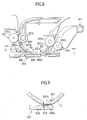
- the reading section 422 is formed as shown in Figs. 8 to 11.
- Fig. 8 is an enlarged side view of the reading section.
- Fig. 9 is an enlarged side view showing the arrangement of the reading guide member and positioning member.
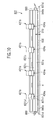
- Fig. 10 is a view of the reading section which is seen from the direction of an arrow L of Fig. 8.
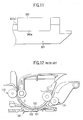
- Fig. 11 is a view of the reading section which is seen from the direction of an arrow R of Fig. 8.
- a slit glass plate 830 is arranged in the reading section 422 of this embodiment.
- a reading guide member 831 is arranged to oppose the slit glass plate 830.
- the reading guide member 831 is integrally formed of a resin into a plate, and its center 831a forms a flat surface that opposes the slit glass plate 830.
- a front end 831b of the reading guide member 831 extends to the position of the registration rollers 421.
- the front end 831b has a notch 831b1 where the registration rollers 421 are located.
- a rear end 831c of the reading guide member 831 extends to the position of the convey rollers 424.
- the rear end 831c has a notch 831c1 where the convey rollers 424 are located.
- the reading guide member 831 has a pair of attaching portions 831d, as shown in Fig. 10.
- the attaching portions 831d are attached to the document convey section 400 with fastening means 880 such as machine screws.
- the reading guide member 831 has a positioning member 840 that determines the gap between the reading guide member 831 and slit glass plate 830.
- the positioning member of this embodiment is formed of a pair of projections 840a abutting against the slit glass plate 830, as shown in Fig. 10.
- the pair of projections 840a are integrally formed with the reading guide member 831, and are located on two sides of the convey direction of the convey path which is formed by a gap D10 between the center 831a and slit glass plate 830 and along which the document d is conveyed.
- the reading guide member 831 and the pair of projections 840a serving as the positioning member are formed integrally, the number of components can be reduced, and the cost can be reduced. Since the slit glass plate 830 is positioned by the projections 840a integral with the reading guide member 831 and serving as the positioning member, assembly errors can be reduced, and the precision of the convey path formed by the gap D10 between the slit glass plate 830 and the center 831a of the reading guide member 831 can be improved.
- the reading guide member 831 is made of a resin and the pair of projections 840a serving as the positioning member are formed of a resin to be integral with the reading guide member 831, a further cost reduction becomes possible.
- a reading guide member 850 is arranged upstream of the reading section 422 in the convey direction to oppose the reading guide member 831.
- the reading guide member 850 is integrally formed of a resin into a plate.
- the pair of reading guide members 831 and 850 guide the document d from rollers 421a and 421b, serving as the registration rollers 421, to the reading section 422.
- the roller 421a is a driven roller
- the roller 421b is a driving roller.
- the pair of reading guide members 831 and 850 form a convey path P5 with a curvature to extend from the pair of rollers 421a and 421b to the reading section 422.
- the document d is conveyed along the convey path P5, and is read by the reading section 422.
- a flexible member 980 is adhered at that position of the reading guide member 831 where the notch 831b1 is not formed, that is, to the non-notched portion of the reading guide member 831.
- an end 980a of the flexible member 980 is attached to close the convey path P5.
- the end 980a of the flexible member 980 flexes by the passing force of the document d, so it allows conveyance. Because of the end 980a of the flexible member 980, the document d abuts against the reading guide member 850, so that the document d is always conveyed along the convey path P5.
- the flexible member 980 is formed of a low-cost PET sheet, and is arranged at that end 831b of the reading guide member 831 which is upstream in the convey direction. Because of the flexible member 980, the document d is always conveyed along the convey path P5. Thus, when the document d which has been clamped by both the pre-reading registration rollers 421 and post-reading convey rollers 424 passes through the pre-reading registration rollers 421 and is supported by only the post-reading convey rollers 424, it can be suppressed from flapping in the convey path P5.
- the flexible member 980 with which the document d is always conveyed in the convey path P5 along the convey path P5 is formed.
- the flexible member 980 is attached to close the convey path P5.
- the flexible member 980 is formed between the pre-reading registration rollers 421 and the reading section 422, but the present invention is not limited to this. It suffices as far as the flexible member 980 is arranged such that the document d is always conveyed in the convey path P5 along the convey path P5.
- the embodiment of the present invention shows a document feeder connected to a copying machine.
- the present invention can also be applied to a document feeder which is used in connection with an image forming apparatus such as a printer or facsimile apparatus, a multifunctional machine having a plurality of functions of these image forming apparatuses, a light printing machine, or the like.
Landscapes
- Engineering & Computer Science (AREA)
- Multimedia (AREA)
- Signal Processing (AREA)
- Physics & Mathematics (AREA)
- General Physics & Mathematics (AREA)
- Exposure Or Original Feeding In Electrophotography (AREA)
- Feeding Of Articles By Means Other Than Belts Or Rollers (AREA)
- Facsimiles In General (AREA)
- Facsimile Scanning Arrangements (AREA)
Abstract
Description
- The present invention relates to a document feeder which can convey a document and enable image reading in order to form an image with an image forming apparatus such as an electrophotographic copying machine, a printer, a facsimile apparatus, a multifunctional machine having a plurality of these functions, or a printing machine, and an image forming apparatus.
- In some document feeder provided to such a digital image forming apparatus, documents placed on the sheet feed tray are separated one by one and conveyed by a document convey section. The documents can then be read by a reading section.
- In this document feeder, as shown in Fig. 12, a
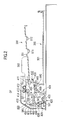
slit glass plate 101 is arranged in areading section 100. Areading guide member 102 is arranged at a position opposing theslit glass plate 101. A convey path is formed by adistance 103 between theslit glass plate 101 andreading guide member 102. A document conveyed through this convey path is read. - With this arrangement, when a document d which has been clamped by both a pair of pre-reading convey
rollers 110 and a pair of post-reading conveyrollers 111 passes through thepre-reading convey rollers 110 and is clamped by only the post-reading conveyrollers 111, it sometimes flaps in the convey path. This causes fluctuations in convey speed to form a defective image. - The present invention has been made in order to solve the above inconvenience, and has as its object to provide a document feeder which suppresses flapping of a document in a convey path so that a defective image can be prevented from being formed by fluctuations in convey speed, and an image forming apparatus.
- In order to solve the above problem and to achieve the above object, the present invention has the following aspects.
- According to the first aspect of the present invention, there is provided a document feeder which conveys a document with a document feeding section and reads the document at a reading section, comprising a flexible member with which the document is always conveyed along a convey path without deviation.
- With the document feeder according to this aspect, the document is always conveyed along the convey path. Flapping of the document is suppressed, and fluctuations in convey speed can be reduced with a simple arrangement, so that a defective image can be prevented.
- According to the second aspect of the present invention, in the document feeder according to the first aspect, the flexible member is attached to close the convey path.
- With the document feeder according to the second aspect, since the flexible member is attached to close the convey path, flapping of the document is suppressed with a simple arrangement, so that fluctuations in convey speed can be reduced.
- According to the third aspect of the present invention, in the document feeder according to the first or second aspect, the flexible member is a PET sheet.
- With the document feeder according to the third aspect, the flexible member is a PET sheet, so the cost is low.
- According to the fourth aspect of the present invention, there is provided an image forming apparatus comprising a document feeder according to any one of the first to third aspects.
- The image forming apparatus according to the fourth aspect comprises a document feeder according to any one of the first to third aspects, which suppresses flapping of a document in a convey path, so that a defective image can be prevented from being formed by fluctuations in convey speed.
- The above and many other objects, features and advantages of the present invention will become manifest to those skilled in the art upon making reference to the following detailed description and accompanying drawings in which a preferred embodiment incorporating the principle of the present invention is shown by way of illustrative examples.
-
- Fig. 1 is a view showing the schematic entire arrangement of an image forming apparatus having a sheet post-processor, document feeder, and image reader;
- Fig. 2 is a schematic longitudinal sectional view of the document feeder;
- Fig. 3 is a schematic plan view of the document feeder;
- Fig. 4 is an enlarged sectional view of the main part of the document feeder;
- Fig. 5 is an enlarged sectional view showing a convey switching section;
- Fig. 6 is an enlarged sectional view showing a single-sided convey path in sheet conveyance;
- Fig. 7 is an enlarged sectional view showing a double-sided convey path in sheet conveyance;
- Fig. 8 is an enlarged side view having a partial longitudinal section of an image reading section;
- Fig. 9 is an enlarged longitudinal sectional view showing the main part of the side view of the image reading section;
- Fig. 10 is a partial view of the image reading section which is seen from the direction of an arrow L of Fig. 8;
- Fig. 11 is a view of the image reading section which is seen from the direction of an arrow R of Fig. 8; and
- Fig. 12 is an enlarged side view having a partial longitudinal section of a conventional image reading section.
-
- A preferred embodiment of the present invention will be described with reference to the accompanying drawings. Note that the present invention is not limited to this embodiment.
- Fig. 1 is a view showing the entire arrangement of an
image forming apparatus 1 having a sheet postprocessor FS, document feeder DF, and image reader (scanner) SC. - An image forming apparatus
main body 1A shown in Fig. 1 has animage processing section 2, image writing section 3, image forming section 4, high-voltage power supplies 5,feed cassettes 6, fixing device 7,delivery section 8, and re-conveying means (ADU) 9 for automatic double-sided copying operation. - The image reader SC and document feeder DF are mounted on the upper portion of the image forming apparatus
main body 1A. The sheet post-processor FS is connected to thedelivery section 8 at the upper left (Fig. 1) of the image forming apparatusmain body 1A. - A document d placed on the document table of the document feeder DF with its first side facing up is conveyed in the direction of arrows. An image on the one side of the document or images on the two sides of the document are read by the optical system of the image reader SC, and are loaded by a CCD image sensor C1.
- An analog signal obtained by photoelectric conversion of the CCD image sensor C1 is processed by the
image processing section 2 in accordance with an analog process, A/D conversion, shading correction, an image compressing process, and the like, and is sent to the image writing section 3. - In the image writing section 3, an output light beam from a semiconductor laser irradiates a
photosensitive drum 4A of the image forming section 4 to form a latent image. The image forming section 4 performs processes such as charging, exposure, development, transfer, separation, and cleaning, and the image is transferred to a sheet S conveyed from thecorresponding feed cassette 6. The image-bearing sheet S is fixed by the fixing device 7, and is fed from thedelivery section 8 to the sheet postprocessor FS. Alternatively, the sheet S, which has been subjected to a single-sided image process and sent to the re-conveying means 9 by a deliverypath switching plate 8A, is subjected to a double-sided image process by the image forming section 4 again, and is sent to the sheet postprocessor FS bydelivery rollers 8B of thedelivery section 8. - The sheet postprocessor FS is detachably mounted at the upper left of the image forming apparatus
main body 1A. The sheet postprocessor FS is comprised of a sheet conveying means 10, delivery means 20, postprocessing means 30, and vertically movable delivery means 40, which are arranged in a sheet postprocessormain body 45. - Referring to Fig. 1, on the right side in the image forming apparatus
main body 1A, thefeed cassettes 6, and the fixing device 7 anddelivery section 8 are arranged below and above, respectively, the image forming apparatusmain body 1A around the image forming section 4 in the direction of height. This vertical array forms a substantially vertical sheet conveypath 1 ○. The sheet S sent from eachfeed cassette 6 is conveyed along the sheet conveypath 1 ○ vertically above it and is delivered to outside the image forming apparatusmain body 1A. - A sheet convey
path 2 ○ is formed by the re-conveying means 9 to be substantially parallel to the vertical sheet conveypath 1 ○. - When the vertical sheet convey
paths 1 ○ and 2 ○ are formed, a sheet convey path with a minimum distance is formed to extend from thefeed cassettes 6 to thedelivery section 8. - The sheet conveying means 10 of the sheet postprocessor FS is accommodated in the upper space (in Fig. 1) of the image forming apparatus
main body 1A. Asheet inlet 11 of the sheet conveying means 10 is connected to thedelivery rollers 8B of thedelivery section 8 of the image forming apparatusmain body 1A. In this mounting state, the delivery means 20 and postprocessing means 30 of the sheet postprocessor FS are accommodated in the upper left space (in Fig. 1) of the image forming apparatusmain body 1A. The vertically movable delivery means 40 formed of a plurality of sheet delivery trays (to be also referred to as bins) 41 and a vertically movable driving means 42 is located on the left side (in Fig. 1) of the postprocessing means 30. - As apparent from Fig. 2, a
document feeding section 200,document delivery section 300, and document conveysection 400 are arranged in the document feeder DF. - The
document feeding section 200 has asheet feed tray 201 on which a plurality of documents can be set. A pair of regulatingplates 202 for positioning the documents in the widthwise direction are provided to thesheet feed tray 201 to be movable in the widthwise direction. Two sensors respectively constituting lengthwise direction detecting means S11 and S12 for detecting the lengthwise direction of the document are arranged on thesheet feed tray 201. - The
document delivery section 300 has asheet delivery tray 301 which is arranged below thedocument feeding section 200. The document which is conveyed by the document conveysection 400 such that its one side or two sides will be read is delivered onto thesheet delivery tray 301. - The document convey
section 400 has an upstream first conveypath 410, downstream branching second and third conveypaths delivery section 440. Amovable press plate 411,pickup roller 412, separating conveyroller 413, and double-feedpreventive roller 414 are arranged along the first conveypath 410. Themovable press plate 411 moves up each time a document is fed, and urges the document against thepickup roller 412, so the document is urged against the separating conveyroller 413. The separating conveyroller 413 and double-feedpreventive roller 414 separate the documents one by one and convey the separated documents. A sensor constituting a document length detecting means S21 is arranged downstream of the separating conveyroller 413 and double-feedpreventive roller 414. -
Registration rollers 421, readingsection 422, readingpress roller 423, and conveyrollers 424 are arranged along the second conveypath 420. A sensor constituting a document leading end detecting means S31 is arranged downstream of theregistration rollers 421. Theregistration rollers 421, readingpress roller 423, and conveyrollers 424 can rotate forward in the document convey direction. - Convey
rollers 431 and reversingsection 432 are arranged along the third conveypath 430. The reversingsection 432 has reversingrollers 433. The conveyrollers 431 and reversingrollers 433 can rotate in the forward and reverse directions.Delivery rollers 441 are arranged in thedelivery section 440. - The first convey
path 410 has afirst switching member 450 which can be switched from the first conveypath 410 to the downstream second or third conveypath first switching member 450 is pivotal together with asupport shaft 453. Anarm 453a is formed on one end of thesupport shaft 453, and anarm 453b is formed on the other end of thesupport shaft 453. Thearm 453a is biased by aspring 451. Thefirst switching member 450 opens the second conveypath 420 and closes the third conveypath 430. Thearm 453b is actuated by asolenoid 452 against thespring 451. When thesolenoid 452 is actuated, thearm 453b closes the second conveypath 420 and opens the third conveypath 430. - Integrally formed second and
third switching members support shaft 453. The second andthird switching members spring 471. Thesecond switching member 460 opens the second conveypath 420, and thethird switching member 470 closes the third conveypath 430. - The
second switching member 460 which is biased from both the first and third conveypaths path 420. Thesecond switching member 460 is biased by thespring 471 to allow conveyance from the first conveypath 410 and to regulate conveyance from the third conveypath 430. When a document is conveyed from the third conveypath 430, thesecond switching member 460 is automatically opened by the document, so that the document can be conveyed. - The
third switching member 470 which is biased from both the first and second conveypaths path 430. Thethird switching member 470 is biased by thespring 471 to regulate conveyance from the first conveypath 410 and to allow conveyance from the third conveypath 430. When a document is conveyed from the first conveypath 410, thethird switching member 470 is automatically opened by the document, so that the document can be conveyed. - The first, second, and
third switching members support shaft 453 arranged at the merging portion of the first, second, and third conveypaths - As shown in Fig. 5, a
fourth switching member 490 that can allow switching between the reversingsection 432 anddelivery section 440 is provided downstream of thereading section 422 to be rotatable together with asupport shaft 493. Anarm 493a is formed on one end of thesupport shaft 493, and anarm 493b is formed on the other end of thesupport shaft 493. Thearm 493a is biased by aspring 491 to open aninlet 440a of thedelivery section 440 and to close aninlet 432a of the reversingsection 432. Thearm 493b is actuated by asolenoid 492 against thespring 491. When thesolenoid 492 is actuated, thearm 493b closes theinlet 440a of thedelivery section 440 and opens theinlet 432a of the reversingsection 432. - In this embodiment, when one side of a document d is to be read, the document d is conveyed along a single-sided sheet path P1 along which one side of the document d is to be read and the document d is to be delivered, as shown in Fig. 6.
- More specifically, in Fig. 6, the documents d placed on the
sheet feed tray 201 are separated and conveyed one by one, and thefirst switching member 450 closes the third conveypath 430. Hence, each document d is conveyed from the first conveypath 410 to the second conveypath 420, and its one side is read by thereading section 422. Thefourth switching member 490 closes theinlet 432a of the reversingsection 432 and opens theinlet 440a of thedelivery section 440. Hence, the document d which has been read is delivered onto thesheet delivery tray 301 through thedelivery section 440. - When the two sides of the document d are to be read, as shown in Fig. 7, the document d is conveyed along a double-sided sheet path P2. Along the double-sided sheet path P2, the document d is guided to the reversing
section 432, reversed, and conveyed. One side of the document d is read by thereading section 422, and then the document d is guided to the reversingsection 432. The document d is reversed again by the reversingsection 432 and conveyed. The other side of the document d is read by thereading section 422, and the document d is delivered. - More specifically, in Fig. 7, the documents d placed on the
sheet feed tray 201 are separated and conveyed one by one. Thesolenoid 452 actuates thefirst switching member 450 to open the third conveypath 430, so the document d is conveyed from the first conveypath 410 to the third conveypath 430. Thethird switching member 470 arranged on the third conveypath 430 closes the third conveypath 430. Thethird switching member 470 is pushed by the document d which is being conveyed, and opens against thespring 471. When the document d passes, thethird switching member 470 closes. - Along the third convey
path 430, the conveyrollers 431 and the reversingrollers 433 of the reversingsection 432 rotate in the forward direction to load the document d. The conveyrollers 431 and reversingrollers 433 then rotate in the reverse direction to switch back the document d and convey it. The document d is conveyed from the third conveypath 430 to the second conveypath 420 through the second andthird switching members reading section 422. - When the document d is to be switched back and conveyed, the second and
third switching members spring 471. The document d which is being switched back and conveyed is guided by thethird switching member 470 to push thesecond switching member 460. Thesecond switching member 460 is pushed by the document d which is being conveyed, and opens against thespring 471. When the document d passes, thesecond switching member 460 closes. - The
solenoid 492 actuates thefourth switching member 490 to open theinlet 432a of the reversingsection 432 and to close theinlet 440a of thedelivery section 440. Hence, the document d which has been read is sent to the reversingsection 432 through theinlet 432a of the reversingsection 432. The conveyrollers 431 and reversingrollers 433 rotate in the reverse direction to switch back the document d and convey it. The document d is then conveyed from the third conveypath 430 to the second conveypath 420 through the second andthird switching members reading section 422. - The
fourth switching member 490 closes theinlet 432a of the reversingsection 432 and opens theinlet 440a of thedelivery section 440. Hence, the document d which has been read is delivered onto thesheet delivery tray 301 through thedelivery section 440. - The document feeder that can perform single-sided reading of the document d and double-sided reading of the document d has a document registration mechanism A in which the leading end of the document d is jogged by abutting against a pair of rollers arranged upstream of the
reading section 422 and downstream of the reversingsection 432. The document registration mechanism A is formed of theregistration rollers 421. The document registration mechanism A is arranged upstream of thereading section 422 and downstream of the reversingsection 432. The leading end of the document d is jogged by abutting against the pair of rollers of the document registration mechanism A. Thus, any ramp of the document d can be corrected at one location in both single-sided reading and double-sided reading. - A registration loop forming space SP1 for allowing a loop of the document d, which occurs when jogging the document d with the document registration mechanism A, is formed along the single-sided sheet path P1. A registration loop forming space SP2 is formed along the double-sided sheet path P2. A loop of the document d, which occurs when jogging the document d with the document registration mechanism A, is allowed by the registration loop forming spaces SP1 and SP2. Thus, reliable ramp correction can be performed for both single-sided reading and double-sided reading of the document d.
- A document position detecting means S41 is arranged upstream of the document registration mechanism A. Since the document position detecting means S41 for detecting the position of the document d is arranged immediately after the merging point of the single-sided sheet path P1 and double-sided sheet path P2, the position of the document d can be detected in both single-sided reading and double-sided reading of the document d.
- In this embodiment, the
reading section 422 is formed as shown in Figs. 8 to 11. Fig. 8 is an enlarged side view of the reading section. Fig. 9 is an enlarged side view showing the arrangement of the reading guide member and positioning member. Fig. 10 is a view of the reading section which is seen from the direction of an arrow L of Fig. 8. Fig. 11 is a view of the reading section which is seen from the direction of an arrow R of Fig. 8. - A
slit glass plate 830 is arranged in thereading section 422 of this embodiment. A readingguide member 831 is arranged to oppose theslit glass plate 830. - The reading
guide member 831 is integrally formed of a resin into a plate, and itscenter 831a forms a flat surface that opposes theslit glass plate 830. Afront end 831b of the readingguide member 831 extends to the position of theregistration rollers 421. Thefront end 831b has a notch 831b1 where theregistration rollers 421 are located. Arear end 831c of the readingguide member 831 extends to the position of the conveyrollers 424. Therear end 831c has a notch 831c1 where the conveyrollers 424 are located. - The reading
guide member 831 has a pair of attachingportions 831d, as shown in Fig. 10. The attachingportions 831d are attached to the document conveysection 400 with fastening means 880 such as machine screws. - The reading
guide member 831 has a positioning member 840 that determines the gap between the readingguide member 831 and slitglass plate 830. The positioning member of this embodiment is formed of a pair ofprojections 840a abutting against theslit glass plate 830, as shown in Fig. 10. The pair ofprojections 840a are integrally formed with the readingguide member 831, and are located on two sides of the convey direction of the convey path which is formed by a gap D10 between thecenter 831a and slitglass plate 830 and along which the document d is conveyed. - In this manner, when the reading
guide member 831 and the pair ofprojections 840a serving as the positioning member are formed integrally, the number of components can be reduced, and the cost can be reduced. Since theslit glass plate 830 is positioned by theprojections 840a integral with the readingguide member 831 and serving as the positioning member, assembly errors can be reduced, and the precision of the convey path formed by the gap D10 between theslit glass plate 830 and thecenter 831a of the readingguide member 831 can be improved. - Since the reading
guide member 831 is made of a resin and the pair ofprojections 840a serving as the positioning member are formed of a resin to be integral with the readingguide member 831, a further cost reduction becomes possible. - According to this embodiment, a reading
guide member 850 is arranged upstream of thereading section 422 in the convey direction to oppose the readingguide member 831. The readingguide member 850 is integrally formed of a resin into a plate. The pair of readingguide members rollers registration rollers 421, to thereading section 422. - The
roller 421a is a driven roller, and theroller 421b is a driving roller. The pair of readingguide members rollers reading section 422. The document d is conveyed along the convey path P5, and is read by thereading section 422. - According to this embodiment, between the pair of
pre-reading rollers reading section 422, aflexible member 980 is adhered at that position of the readingguide member 831 where the notch 831b1 is not formed, that is, to the non-notched portion of the readingguide member 831. As shown in Figs. 8 and 11, anend 980a of theflexible member 980 is attached to close the convey path P5. Theend 980a of theflexible member 980 flexes by the passing force of the document d, so it allows conveyance. Because of theend 980a of theflexible member 980, the document d abuts against the readingguide member 850, so that the document d is always conveyed along the convey path P5. - The
flexible member 980 is formed of a low-cost PET sheet, and is arranged at thatend 831b of the readingguide member 831 which is upstream in the convey direction. Because of theflexible member 980, the document d is always conveyed along the convey path P5. Thus, when the document d which has been clamped by both thepre-reading registration rollers 421 and post-reading conveyrollers 424 passes through thepre-reading registration rollers 421 and is supported by only the post-reading conveyrollers 424, it can be suppressed from flapping in the convey path P5. - In this manner, the
flexible member 980 with which the document d is always conveyed in the convey path P5 along the convey path P5 is formed. Theflexible member 980 is attached to close the convey path P5. With this simple arrangement, the document d can be conveyed along the outer surface of the readingguide member 831, and fluctuations in the convey speed can be reduced, thereby preventing a defective image. - In this embodiment, the
flexible member 980 is formed between thepre-reading registration rollers 421 and thereading section 422, but the present invention is not limited to this. It suffices as far as theflexible member 980 is arranged such that the document d is always conveyed in the convey path P5 along the convey path P5. - The embodiment of the present invention shows a document feeder connected to a copying machine. The present invention can also be applied to a document feeder which is used in connection with an image forming apparatus such as a printer or facsimile apparatus, a multifunctional machine having a plurality of functions of these image forming apparatuses, a light printing machine, or the like.
Claims (10)
- A document feeder which reads a document at a reading section while conveying the document in a document feeding section, comprising
a flexible member which is set in a convey path formed in the document feeding section such that the document is always conveyed along the convey path, and which flexes by a passing force of the document, to allow conveyance of the document. - A document feeder according to claim 1, wherein said flexible member is adhered to a reading guide member provided to the document feeding section, to close the convey path.
- A document feeder according to claim 1, wherein said flexible member is a PET sheet.
- A document feeder according to claim 2, wherein said flexible member is a PET sheet.
- An image forming apparatus comprising the document feeder according to claim 1.
- An image forming apparatus comprising the document feeder according to claim 2.
- An image forming apparatus comprising the document feeder according to claim 3.
- A document feeder according to claim 2, further comprising a positioning member, between the reading guide member and a slit glass plate opposing the reading guide member, to determine a distance between the reading guide member and the slit glass plate.
- A document feeder according to claim 4, further comprising a positioning member, between the reading guide member and a slit glass plate opposing the reading guide member, to determine a distance between the reading guide member and the slit glass plate.
- A document feeder according to claim 6, further comprising a positioning member, between the reading guide member and a slit glass plate opposing the reading guide member, to determine a distance between the reading guide member and the slit glass plate.
Applications Claiming Priority (2)
| Application Number | Priority Date | Filing Date | Title |
|---|---|---|---|
| JP2002014527A JP2003212382A (en) | 2002-01-23 | 2002-01-23 | Original carrier device and picture image formation device |
| JP2002014527 | 2002-01-23 |
Publications (2)
| Publication Number | Publication Date |
|---|---|
| EP1333334A1 true EP1333334A1 (en) | 2003-08-06 |
| EP1333334B1 EP1333334B1 (en) | 2011-06-29 |
Family
ID=19191883
Family Applications (1)
| Application Number | Title | Priority Date | Filing Date |
|---|---|---|---|
| EP03250095A Expired - Lifetime EP1333334B1 (en) | 2002-01-23 | 2003-01-08 | Document feeder and image forming apparatus |
Country Status (3)
| Country | Link |
|---|---|
| US (1) | US7443551B2 (en) |
| EP (1) | EP1333334B1 (en) |
| JP (1) | JP2003212382A (en) |
Families Citing this family (4)
| Publication number | Priority date | Publication date | Assignee | Title |
|---|---|---|---|---|
| JP2006056679A (en) * | 2004-08-20 | 2006-03-02 | Konica Minolta Business Technologies Inc | Paper feeder |
| JP2007180844A (en) * | 2005-12-27 | 2007-07-12 | Canon Inc | Image reading apparatus and image forming apparatus |
| TWI331982B (en) * | 2007-05-25 | 2010-10-21 | Teco Image System Co Lted | Automatic document feeder and multi-function printer using the same |
| JP4669025B2 (en) * | 2008-06-06 | 2011-04-13 | シャープ株式会社 | Image processing apparatus and image processing method |
Citations (4)
| Publication number | Priority date | Publication date | Assignee | Title |
|---|---|---|---|---|
| US4761001A (en) * | 1984-07-10 | 1988-08-02 | Canon Kabushiki Kaisha | Automatic document feeder |
| US4933717A (en) * | 1988-01-11 | 1990-06-12 | Konica Corporation | Document feeder |
| US4975749A (en) * | 1988-06-17 | 1990-12-04 | Ricoh Company, Ltd. | Automatic document feeder |
| US5090682A (en) * | 1989-06-28 | 1992-02-25 | Mita Industrial Co., Ltd. | Automatic document feeder comprising a guide member |
Family Cites Families (6)
| Publication number | Priority date | Publication date | Assignee | Title |
|---|---|---|---|---|
| US5651623A (en) * | 1993-10-29 | 1997-07-29 | Hewlett-Packard Company | Multiple-function printer with common feeder/output path mechanisms and method of operation |
| JP3730016B2 (en) * | 1998-06-23 | 2005-12-21 | 株式会社リコー | Paper separating and conveying device |
| JP3487196B2 (en) | 1998-10-23 | 2004-01-13 | セイコーエプソン株式会社 | Automatic document feeder |
| US6398212B1 (en) * | 1998-12-18 | 2002-06-04 | Canon Kabushiki Kaisha | Sheet surface reversing device and image forming apparatus having the same |
| JP3548449B2 (en) * | 1999-02-01 | 2004-07-28 | キヤノン株式会社 | Sheet conveying device and image forming apparatus provided with the device |
| JP3883907B2 (en) * | 2002-05-31 | 2007-02-21 | シャープ株式会社 | Double-sided image reader |
-
2002
- 2002-01-23 JP JP2002014527A patent/JP2003212382A/en active Pending
-
2003
- 2003-01-06 US US10/337,304 patent/US7443551B2/en not_active Expired - Fee Related
- 2003-01-08 EP EP03250095A patent/EP1333334B1/en not_active Expired - Lifetime
Patent Citations (4)
| Publication number | Priority date | Publication date | Assignee | Title |
|---|---|---|---|---|
| US4761001A (en) * | 1984-07-10 | 1988-08-02 | Canon Kabushiki Kaisha | Automatic document feeder |
| US4933717A (en) * | 1988-01-11 | 1990-06-12 | Konica Corporation | Document feeder |
| US4975749A (en) * | 1988-06-17 | 1990-12-04 | Ricoh Company, Ltd. | Automatic document feeder |
| US5090682A (en) * | 1989-06-28 | 1992-02-25 | Mita Industrial Co., Ltd. | Automatic document feeder comprising a guide member |
Also Published As
| Publication number | Publication date |
|---|---|
| EP1333334B1 (en) | 2011-06-29 |
| US20030137703A1 (en) | 2003-07-24 |
| US7443551B2 (en) | 2008-10-28 |
| JP2003212382A (en) | 2003-07-30 |
Similar Documents
| Publication | Publication Date | Title |
|---|---|---|
| US7110148B2 (en) | Duplex image reading apparatus | |
| US10440213B2 (en) | Image reading apparatus and image forming apparatus | |
| US6775513B2 (en) | Image forming apparatus having removable angle stopper | |
| US8913309B2 (en) | Image reading apparatus and image forming apparatus | |
| EP1333334B1 (en) | Document feeder and image forming apparatus | |
| JP3547833B2 (en) | Image forming device | |
| CN100520612C (en) | Paper feed structure for an image forming apparatus | |
| US8360419B2 (en) | Sheet feeding apparatus and image forming apparatus | |
| JP5021532B2 (en) | Image reader | |
| JP4521037B2 (en) | Image reading apparatus and composite apparatus | |
| JP2001253613A (en) | Paper transport mechanism | |
| JPH07301962A (en) | Document reader | |
| US12221305B2 (en) | Document conveying apparatus, image reading apparatus and image forming apparatus | |
| US20180234576A1 (en) | Image reading apparatus and image forming apparatus | |
| JP2001309118A (en) | Document feeder | |
| US12214980B2 (en) | Document conveying apparatus, image reading apparatus and image forming apparatus | |
| JP5068721B2 (en) | Automatic document feeder and image forming apparatus | |
| JP2003063667A (en) | Document feeder and image forming device | |
| JP3602321B2 (en) | Automatic document feeder | |
| JP3964277B2 (en) | Image reading device | |
| JP2003069788A (en) | Original feeder and image forming device | |
| JP6579437B2 (en) | Document conveying apparatus and image forming apparatus | |
| JP2005075564A (en) | Document carrying device and image forming device | |
| JP3359162B2 (en) | Automatic document feeder and image forming apparatus having the same | |
| JP2003081445A (en) | Document feeder and image forming device |
Legal Events
| Date | Code | Title | Description |
|---|---|---|---|
| PUAI | Public reference made under article 153(3) epc to a published international application that has entered the european phase |
Free format text: ORIGINAL CODE: 0009012 |
|
| AK | Designated contracting states |
Designated state(s): AT BE BG CH CY CZ DE DK EE ES FI FR GB GR HU IE IT LI LU MC NL PT SE SI SK TR |
|
| AX | Request for extension of the european patent |
Extension state: AL LT LV MK RO |
|
| 17P | Request for examination filed |
Effective date: 20031006 |
|
| 17Q | First examination report despatched |
Effective date: 20031212 |
|
| AKX | Designation fees paid |
Designated state(s): DE GB |
|
| GRAP | Despatch of communication of intention to grant a patent |
Free format text: ORIGINAL CODE: EPIDOSNIGR1 |
|
| GRAS | Grant fee paid |
Free format text: ORIGINAL CODE: EPIDOSNIGR3 |
|
| GRAA | (expected) grant |
Free format text: ORIGINAL CODE: 0009210 |
|
| AK | Designated contracting states |
Kind code of ref document: B1 Designated state(s): DE GB |
|
| REG | Reference to a national code |
Ref country code: GB Ref legal event code: FG4D |
|
| REG | Reference to a national code |
Ref country code: DE Ref legal event code: R096 Ref document number: 60337533 Country of ref document: DE Effective date: 20110818 |
|
| PLBE | No opposition filed within time limit |
Free format text: ORIGINAL CODE: 0009261 |
|
| STAA | Information on the status of an ep patent application or granted ep patent |
Free format text: STATUS: NO OPPOSITION FILED WITHIN TIME LIMIT |
|
| 26N | No opposition filed |
Effective date: 20120330 |
|
| REG | Reference to a national code |
Ref country code: DE Ref legal event code: R097 Ref document number: 60337533 Country of ref document: DE Effective date: 20120330 |
|
| PGFP | Annual fee paid to national office [announced via postgrant information from national office to epo] |
Ref country code: GB Payment date: 20190102 Year of fee payment: 17 Ref country code: DE Payment date: 20181228 Year of fee payment: 17 |
|
| REG | Reference to a national code |
Ref country code: DE Ref legal event code: R119 Ref document number: 60337533 Country of ref document: DE |
|
| GBPC | Gb: european patent ceased through non-payment of renewal fee |
Effective date: 20200108 |
|
| PG25 | Lapsed in a contracting state [announced via postgrant information from national office to epo] |
Ref country code: DE Free format text: LAPSE BECAUSE OF NON-PAYMENT OF DUE FEES Effective date: 20200801 Ref country code: GB Free format text: LAPSE BECAUSE OF NON-PAYMENT OF DUE FEES Effective date: 20200108 |