EP1333333B1 - Module to module attaching and securing apparatus - Google Patents
Module to module attaching and securing apparatus Download PDFInfo
- Publication number
- EP1333333B1 EP1333333B1 EP03002125A EP03002125A EP1333333B1 EP 1333333 B1 EP1333333 B1 EP 1333333B1 EP 03002125 A EP03002125 A EP 03002125A EP 03002125 A EP03002125 A EP 03002125A EP 1333333 B1 EP1333333 B1 EP 1333333B1
- Authority
- EP
- European Patent Office
- Prior art keywords
- module
- screw
- attaching
- securing apparatus
- securing
- Prior art date
- Legal status (The legal status is an assumption and is not a legal conclusion. Google has not performed a legal analysis and makes no representation as to the accuracy of the status listed.)
- Expired - Lifetime
Links
- 230000000630 rising effect Effects 0.000 claims description 2
- 238000000034 method Methods 0.000 description 9
- 230000008569 process Effects 0.000 description 9
- 239000000463 material Substances 0.000 description 4
- 238000009434 installation Methods 0.000 description 3
- 230000007246 mechanism Effects 0.000 description 3
- 239000002245 particle Substances 0.000 description 3
- 239000000047 product Substances 0.000 description 3
- 238000012358 sourcing Methods 0.000 description 3
- 238000012546 transfer Methods 0.000 description 3
- 230000006378 damage Effects 0.000 description 2
- 238000011161 development Methods 0.000 description 2
- 230000002452 interceptive effect Effects 0.000 description 2
- 230000013011 mating Effects 0.000 description 2
- 238000012545 processing Methods 0.000 description 2
- 208000027418 Wounds and injury Diseases 0.000 description 1
- 230000008901 benefit Effects 0.000 description 1
- 230000008878 coupling Effects 0.000 description 1
- 238000010168 coupling process Methods 0.000 description 1
- 238000005859 coupling reaction Methods 0.000 description 1
- 230000001419 dependent effect Effects 0.000 description 1
- 239000012467 final product Substances 0.000 description 1
- 210000003811 finger Anatomy 0.000 description 1
- 239000008187 granular material Substances 0.000 description 1
- 208000014674 injury Diseases 0.000 description 1
- 238000003780 insertion Methods 0.000 description 1
- 230000037431 insertion Effects 0.000 description 1
- 239000007788 liquid Substances 0.000 description 1
- 238000012986 modification Methods 0.000 description 1
- 230000004048 modification Effects 0.000 description 1
- 210000003813 thumb Anatomy 0.000 description 1
Images



Classifications
-
- F—MECHANICAL ENGINEERING; LIGHTING; HEATING; WEAPONS; BLASTING
- F16—ENGINEERING ELEMENTS AND UNITS; GENERAL MEASURES FOR PRODUCING AND MAINTAINING EFFECTIVE FUNCTIONING OF MACHINES OR INSTALLATIONS; THERMAL INSULATION IN GENERAL
- F16M—FRAMES, CASINGS OR BEDS OF ENGINES, MACHINES OR APPARATUS, NOT SPECIFIC TO ENGINES, MACHINES OR APPARATUS PROVIDED FOR ELSEWHERE; STANDS; SUPPORTS
- F16M7/00—Details of attaching or adjusting engine beds, frames, or supporting-legs on foundation or base; Attaching non-moving engine parts, e.g. cylinder blocks
-
- G—PHYSICS
- G03—PHOTOGRAPHY; CINEMATOGRAPHY; ANALOGOUS TECHNIQUES USING WAVES OTHER THAN OPTICAL WAVES; ELECTROGRAPHY; HOLOGRAPHY
- G03G—ELECTROGRAPHY; ELECTROPHOTOGRAPHY; MAGNETOGRAPHY
- G03G21/00—Arrangements not provided for by groups G03G13/00 - G03G19/00, e.g. cleaning, elimination of residual charge
- G03G21/16—Mechanical means for facilitating the maintenance of the apparatus, e.g. modular arrangements
- G03G21/1604—Arrangement or disposition of the entire apparatus
- G03G21/1619—Frame structures
-
- H—ELECTRICITY
- H05—ELECTRIC TECHNIQUES NOT OTHERWISE PROVIDED FOR
- H05K—PRINTED CIRCUITS; CASINGS OR CONSTRUCTIONAL DETAILS OF ELECTRIC APPARATUS; MANUFACTURE OF ASSEMBLAGES OF ELECTRICAL COMPONENTS
- H05K5/00—Casings, cabinets or drawers for electric apparatus
- H05K5/30—Side-by-side or stacked arrangements
-
- F—MECHANICAL ENGINEERING; LIGHTING; HEATING; WEAPONS; BLASTING
- F16—ENGINEERING ELEMENTS AND UNITS; GENERAL MEASURES FOR PRODUCING AND MAINTAINING EFFECTIVE FUNCTIONING OF MACHINES OR INSTALLATIONS; THERMAL INSULATION IN GENERAL
- F16B—DEVICES FOR FASTENING OR SECURING CONSTRUCTIONAL ELEMENTS OR MACHINE PARTS TOGETHER, e.g. NAILS, BOLTS, CIRCLIPS, CLAMPS, CLIPS OR WEDGES; JOINTS OR JOINTING
- F16B37/00—Nuts or like thread-engaging members
- F16B37/08—Quickly-detachable or mountable nuts, e.g. consisting of two or more parts; Nuts movable along the bolt after tilting the nut
- F16B37/0807—Nuts engaged from the end of the bolt, e.g. axially slidable nuts
- F16B37/0842—Nuts engaged from the end of the bolt, e.g. axially slidable nuts fastened to the threaded bolt with snap-on-action, e.g. push-on nuts for stud bolts
-
- G—PHYSICS
- G03—PHOTOGRAPHY; CINEMATOGRAPHY; ANALOGOUS TECHNIQUES USING WAVES OTHER THAN OPTICAL WAVES; ELECTROGRAPHY; HOLOGRAPHY
- G03G—ELECTROGRAPHY; ELECTROPHOTOGRAPHY; MAGNETOGRAPHY
- G03G2221/00—Processes not provided for by group G03G2215/00, e.g. cleaning or residual charge elimination
- G03G2221/16—Mechanical means for facilitating the maintenance of the apparatus, e.g. modular arrangements and complete machine concepts
- G03G2221/1651—Mechanical means for facilitating the maintenance of the apparatus, e.g. modular arrangements and complete machine concepts for connecting the different parts
-
- G—PHYSICS
- G03—PHOTOGRAPHY; CINEMATOGRAPHY; ANALOGOUS TECHNIQUES USING WAVES OTHER THAN OPTICAL WAVES; ELECTROGRAPHY; HOLOGRAPHY
- G03G—ELECTROGRAPHY; ELECTROPHOTOGRAPHY; MAGNETOGRAPHY
- G03G2221/00—Processes not provided for by group G03G2215/00, e.g. cleaning or residual charge elimination
- G03G2221/16—Mechanical means for facilitating the maintenance of the apparatus, e.g. modular arrangements and complete machine concepts
- G03G2221/1651—Mechanical means for facilitating the maintenance of the apparatus, e.g. modular arrangements and complete machine concepts for connecting the different parts
- G03G2221/1654—Locks and means for positioning or alignment
-
- G—PHYSICS
- G03—PHOTOGRAPHY; CINEMATOGRAPHY; ANALOGOUS TECHNIQUES USING WAVES OTHER THAN OPTICAL WAVES; ELECTROGRAPHY; HOLOGRAPHY
- G03G—ELECTROGRAPHY; ELECTROPHOTOGRAPHY; MAGNETOGRAPHY
- G03G2221/00—Processes not provided for by group G03G2215/00, e.g. cleaning or residual charge elimination
- G03G2221/16—Mechanical means for facilitating the maintenance of the apparatus, e.g. modular arrangements and complete machine concepts
- G03G2221/1678—Frame structures
Definitions
- the present invention relates generally to office machines, and particularly to a removable, low cost and effective user installable module to module attaching and securing apparatus for safely and effectively attaching and securing one machine module to another without tools.
- Office machines include copiers, printers, fax machines, and the like. When delivered to an office after purchase, it is common for some such machines to require securing to a base, o r for those of them that come as modules, for one module to be stacked on, and secured to, another module. This is becoming more of the case with some electrostatographic reproduction machines. As such, it is more economical to have a securing system that can be installed by the purchaser or user rather than by a technical service operator provided by the vendor.
- the process of electrostatographic reproduction includes charging a photoconductive member to a substantially uniform potential so as to sensitize the surface thereof. A charged portion of the photoconductive surface is exposed at an exposure station to a light image of an original document to be reproduced.
- an original document to be reproduced is placed in registration, either manually or by means of an automatic document handler, on a platen for such exposure.
- Exposing an image of an original document as such at the exposure station records an electrostatic latent image of the original image onto the photoconductive member.
- the recorded latent image is subsequently developed using a development apparatus by bringing a charged dry or liquid developer material into contact with the latent image.
- a development apparatus by bringing a charged dry or liquid developer material into contact with the latent image.
- Two component and single component developer materials are commonly used.
- a typical two-component dry developer material has magnetic carrier granules with fusible toner particles adhering triobelectrically thereto.
- a single component dry developer material typically comprising toner particles only can also be used.
- the toner image formed by such development is subsequently transferred at a transfer station onto a copy sheet fed to such transfer station, and on which the toner particles image is then heated and permanently fused so as to form a "hardcopy" of the original image.
- US 5,725,324 describes module latch assembly.
- An effective connector mechanism is described which allows modules to be easily and reliably connected and disconnected.
- This connector mechanism includes a coordinated arrangement of guide plates featuring mating guide rails and U-shaped channels along with matched sets of tapered pins with tapered slots as well as a spring biased latching mechanism. When mated together, the rails, U-shaped channels, pins and slots lock the modules into engagement in every direction except the forward direction.
- a spring biased latching assembly is provided.
- This latching assembly features two symmetrically operating latch handles which are each pivotally connected to a T-shaped pawl.
- the T-shaped pawl When the latch handle is open, the T-shaped pawl rests at the bottom of a ramped runner cut into the walls one module's U-shaped guide channel. As the guide rails from the other module are slid along this U-shaped guide channel, a slot formed in the guide rail of the first module becomes aligned with the ramped runner. At this point, by closing the latch handles, the T-shaped pawl is caused to ride up the ramped runner and into the upper module rail slot in a way which locks the two modules into proper alignment and prevents the upper module from sliding out of engagement through a forward movement. Quick release fasteners are provided at the end of each latch handle to allow the latch handles to be locked into a closed position after the modules are connected.
- US 5,270,772 describes image-forming apparatus having a body formed of vertically separable blocks.
- the apparatus is constructed with a body formed of divided blocks, each of which has a height which is less than each of the width, the depth and the height of the assembled body.
- the divided blocks are connected with each other such that they are vertically separable.
- the respective divided blocks are provided with handles for carrying them with the height dimension thereof oriented horizontally.
- FIG. 7 there is illustrated a frameless exemplary compact electrostatographic reproduction machine 20 comprising separately framed mutually aligning modules according to the present invention.
- T he compact machine 20 is frameless, meaning that it does not have a separate machine frame to which electrostatographic process subsystems are assembled, aligned to the frame, and then aligned relative to one another as is typically the case in conventional machines.
- the architecture of the compact machine 20 is comprised of a number of individually framed, and mutually aligning machine modules that variously include pre-aligned electrostatographic active process subsystems.
- the frameless machine 20 comprises at least a framed copy sheet input module (CIM) 160.
- the machine 20 comprises a pair of copy sheet input modules, a main or primary module the CIM 160, and an auxiliary module the (ACIM) 150, each of which has a set of lugs 156, 162 that are part of the module to module attaching and securing apparatus of the present invention (to be described in detail below), for attaching and securing the ACIM to the CIM.
- the ACIM 150 includes a set of legs 23 for supporting the machine 20 on a surface, for example on the floor.
- each copy sheet input module (CIM, ACIM) includes a module frame 26 and a copy sheet stacking and lifting cassette tray assembly 28 that is slidably movable in and out relative to the module frame 26.
- the machine 20 includes two copy sheet input modules, the very base module is considered the auxiliary module (the ACIM), and the top module which mounts and mutually aligns against the base module is considered the primary module (the CIM).
- the machine 20 next comprises a framed electronic control and power supply (ECS/PS) module 30, that as shown mounts onto, and is mutually aligned against the CIM 160 (which preferably is the top or only copy sheet input module).
- a framed latent image forming imager module 32 then mounts over and is mutually aligned against the ECS/PS module.
- the ECS/PS module 30 includes all controls and power supplies (not shown) for all the modules and processes of the machine 20. It also includes an image processing pipeline unit (IPP) 34 for managing and processing raw digitized images from a Raster Input Scanner (RIS) 36, and generating processed digitized images for a Raster Output Scanner (ROS) 38.
- IPP image processing pipeline unit
- the ECS/PS module 30 also includes harnessless interconnect boards and inter-module connectors (not shown), that provide all power and logic paths to the rest of the machine modules.
- An interconnect board (PWB) (not shown) connects the ECS controller and power supply boards (not shown) to the inter-module connectors., as well as locates all of the connectors to the other modules in such a manner that their mating connectors would automatically plug into the ECS/PS module during the final assembly of the machine 20.
- the ECS/PS module 30 includes a module frame 40 to which the active components of the module as above are mounted, and which forms a covered portion of the machine 20, as well as locates, mutually aligns, and mounts to adjacent framed modules, such as the CIM 160 and the imager module 32.
- the machine 20 importantly includes a customer replaceable, all-in-one CRU or process cartridge module 44 that is insertably and removably mounted within the cavity 42, and in which it is mutually aligned with, and operatively connected to, the framed CIM, ECS/PS and imager modules 160, 30, 32.
- the machine 20 includes a framed fuser module 46, that is mounted above the process cartridge module 44, as well as adjacent an end of the imager module 32.
- the fuser module 46 comprises a pair of fuser rolls 48, 50, and at least an exit roll 52 for moving an image carrying sheet through, and out of, the fuser module 46 into an output or exit tray 54.
- the fuser module also includes a heater lamp 56, temperature sensing means (not shown), paper path handling baffles(not shown), and a module frame 58 to which the active components of the module, as above, are mounted, and which forms a covered portion of the machine 20, as well as locates, mutually aligns, and mounts to adjacent framed modules, such as the imager module 32 and the process cartridge module 44.
- the machine then includes an active component framed door module 60 that is mounted pivotably at pivot point 62 to an end of the CIM 160.
- the door module 60 as mounted is pivotable from a substantially closed vertical position into an open near-horizontal position in order to provide access to the p rocess cartridge module 4 4, as well as for j am clearance of jammed sheets being fed from the CIM 160.
- the Door module 60 comprises active components including a bypass feeder assembly 64, sheet registration rolls 66, toner image transfer and detack devices 68, and the fused image output or exit tray 54.
- the door module 60 also includes drive coupling components and electrical connectors (not shown), and importantly, a module frame 70 to which the active components of the module as above are mounted, and which forms a covered portion of the machine 20, as well as, locates, mutually aligns, and mounts to adjacent framed modules, such as the CIM 160, the process cartridge module 44, and the fuser module 46.
- the machine 20 can be a desktop digital copier, and each of the modules 160, 150, 30, 32, 44, 48, 60, is a high level assembly comprising a self-containing frame including active electrostatographic process components specified for sourcing, and enabled as a complete and shippable product.
- a unique advantage of the machine 20 as such is that its self-standing, specable, testable, and shippable module units specifically allow for high level sourcing to a small set of module-specific skilled production suppliers. Such high level sourcing greatly optimizes the quality, the total cost, and the time of delivering of the final product, the machine 20.
- the whole machine 20 can be attached and secured to a base ( FIG. 6 ) and/or one module thereof can be attached and secured to another module using the module to module attaching and securing apparatus 152, 154 of the present invention (to be described in detail below).
- FIGS. 1-7 the module to module attaching and securing apparatus 152, 154 of the present invention is further illustrated in detail.
- a first embodiment 152 of the securing apparatus of the present invention is shown in FIGS. 1 and 3
- a second embodiment 154 is shown in FIGS. 2 and 4 .
- the first and second embodiments 152, 154 each include a first lug member 156 on the first module 150, 170 having a first set of aligning features 156 (the lug members also serve as aligning or locating members), and a first screw receiving hole 158.
- the embodiments also each include a second lug member 162 on the second module 160, 180 having a second screw receiving hole 164 for aligning with the first screw receiving hole 158, and a second set of aligning features 162 (the lug members also serve as aligning or locating members), for aligning with the first set of aligning features 156.
- the first and second embodiments 152, 154 also each include a ratchet device 190, 200 located inside at least one of the first and the second screw receiving holes 158, 164 for receiving and retaining a screw 166, 168 inserted therethrough.
- the ratchet device 190, 200 includes at least one biased and deflectable spring member 210, 220 having a first normal position ( FIGS. 1 and 3 ) for reducing a diameter D1 of the at least one screw receiving hole 158, 164 to d1 that is substantially less than the outside diameter D2 of an inserted screw 166, 168. They (190, 200) each also have a second deflected position ( FIGS. 2 and 4 ) for engaging surface features 167, 169, (threads 167, and slots 169) of the inserted screw 166, 168 and for effectively retaining the inserted screw within the first and the second screw receiving holes 158, 164.
- the removable screw 166, 168 for manually and easily inserting through the first and the second screw receiving holes has an outside diameter D2 essentially equal to the diameter D1 of each of the first and the second screw receiving holes.
- the surface features 167, 169 threads 167 or slots 169) that are engageable by the ratchet device, thereby enabling easy manual securing and removable attachment of the first module of the office machine to the second module thereof.
- the at least one biased and deflectable spring member 110, 120 in each case has at least one sharp distal edge 192, 202 for effectively engaging the surface features 167, 169 on a surface of the inserted screw 166, 168.
- the surface features 167, 169 of the removable screw 166, 168 comprise (as in the first embodiment 152) screw threads 167 rising above the root diameter surface D3 of the screw 166.
- the root diameter surface also defines the outside diameter D2, and the surface features of the removable screw comprise slots 169 cut into the root diameter surface as such.
- the screw receiving holes 158, 164 are each countersunk from the outside of the lug members 156, 162.
- the customer or user installs the screw 166, 168 in the clearance of the s crew receiving holes or openings 158, 164 simply by using a finger or thumb to push the unique screw through the holes.
- the modules 150, 170 and 160, 180 are located by the lug members 156, 162
- the first and second screw holes 158, 164 are also aligned, thus making such manual insertion relatively easy. This thus eliminates the need for a tool.
- the screw threads 167 or the outside diameter D2 of the screw act to deflect a plastic feature or ratchet device 190, 200, each having the sharp edge 192, 202 within the hole 158, 164 in the locator peg or lug member 156, 162 of the stand or first module 150, 170.
- the plastic feature or ratchet device 190, 200 thus serves to receive and retain the screw 166, 168 and so prevents it from backing out of the holes 158, 164 unexpectedly.
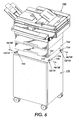
- four such securing and attaching apparatus 152, 154 include at least three sets of module-to-module locating or lug members 156, 162. As shown in FIG. 5 , three sets are used for attaching and securing an auxiliary paper supply tray 150 to another module 160, with two sets mounted at the corners in the front and one mounted to the center in the rear of the modules. In FIG. 6 four sets are used for attaching and securing an image output terminal portion 180 of a copier/printer to a stand module 170, with one set being mounted at each of the four corners of a top of the machine stand 170. As such, four screws are employed as shown.
- the screws are inserted horizontally to attach and secure the printer/copier 180 to the stand or base 170. As shown, two screws are inserted from the right side of the stand 170, and the other two screws are inserted from the left side. This positioning of the apparatus 152, 154, and the screws 166, 168 allows the screws to be visible and easily accessible when required.
- the screws 166, 168 installed as such can be easily removed using a standard flat head or Philips head screw driver by the user or by a field service Engineer if necessary.
- the moveable ratchet device 190, 200 is located within the rear portion of the screw receiving opening or hole 158, 164 for receiving and retaining the screw 166, 168. As shown in FIGS. 2 and 4 , the moveable ratchet device 200 includes a deflectable flat spring front section 222 and a rear, screw thread or slot interfering section 224. The rear portion 224 includes the sharp edge 192, 202, and in one embodiment, the rear portion 224 is triangular as shown. As described above, the ratchet device 190, 200 has a first normal position for interfering and retaining a received screw, and a second position away from interference with a screw being received. It is also deflectable and has a first normal position ( FIGS.
- the attaching and securing apparatus 152, 154 of the present invention is particularly suitable for attaching and securing the printer/copier or image output terminal (IOT) portion 180 of the machine to the base or stand 170. It is also equally suitable for attaching and securing an auxiliary paper feeding module 150 to another module 160. To attach and secure the various modules as such, the attaching and securing apparatus 152, 154 requires no tools, thus enabling it to be considered customer installable.
- the attaching and securing apparatus 152, 154 also enables a field service engineer to easily unsecure and unattach it and so remove the module 1 50, 180 should it require service.
- the uniqueness of the present invention concept lies in the idea of using a low cost flat head screw 166, 168 with a flat or Phillips type recess (not shown) to attach and secure one module 150 to another 160 or to attach and secure the parent product 180 to a base or stand 170.
- an attaching and securing apparatus for removably attaching a first module of an office machine to a second module thereof.
- the attaching and securing apparatus includes (a) a first lug member on the first module having a first set of aligning features and a first screw receiving hole; (b) a second lug member on the second module having a second screw receiving hole for aligning with the first screw receiving hole, and a second set of aligning features for aligning with the first set of aligning features; (c) a ratchet device located inside at least one of the first and the second screw receiving holes for receiving and retaining a screw inserted therethrough, the ratchet device including at least one biased and deflectable spring member having a first normal position for reducing a diameter of the at least one screw receiving hole, and a second deflected position for engaging threads of an inserted screw and for effectively retaining the inserted screw within the first and the second screw receiving holes; and (d) a removable screw for manually and easily inserting
Landscapes
- Engineering & Computer Science (AREA)
- General Engineering & Computer Science (AREA)
- Microelectronics & Electronic Packaging (AREA)
- Physics & Mathematics (AREA)
- General Physics & Mathematics (AREA)
- Mechanical Engineering (AREA)
- Electrophotography Configuration And Component (AREA)
- Accessory Devices And Overall Control Thereof (AREA)
- Connection Of Plates (AREA)
- Insertion Pins And Rivets (AREA)
- Casings For Electric Apparatus (AREA)
Description
- The present invention relates generally to office machines, and particularly to a removable, low cost and effective user installable module to module attaching and securing apparatus for safely and effectively attaching and securing one machine module to another without tools.
- Office machines include copiers, printers, fax machines, and the like. When delivered to an office after purchase, it is common for some such machines to require securing to a base, o r for those of them that come as modules, for one module to be stacked on, and secured to, another module. This is becoming more of the case with some electrostatographic reproduction machines. As such, it is more economical to have a securing system that can be installed by the purchaser or user rather than by a technical service operator provided by the vendor.
- Generally, the process of electrostatographic reproduction, as practiced in electrostatographic reproduction machines, includes charging a photoconductive member to a substantially uniform potential so as to sensitize the surface thereof. A charged portion of the photoconductive surface is exposed at an exposure station to a light image of an original document to be reproduced. Typically, an original document to be reproduced is placed in registration, either manually or by means of an automatic document handler, on a platen for such exposure.
- Exposing an image of an original document as such at the exposure station, records an electrostatic latent image of the original image onto the photoconductive member. The recorded latent image is subsequently developed using a development apparatus by bringing a charged dry or liquid developer material into contact with the latent image. Two component and single component developer materials are commonly used. A typical two-component dry developer material has magnetic carrier granules with fusible toner particles adhering triobelectrically thereto. A single component dry developer material typically comprising toner particles only can also be used. The toner image formed by such development is subsequently transferred at a transfer station onto a copy sheet fed to such transfer station, and on which the toner particles image is then heated and permanently fused so as to form a "hardcopy" of the original image.
- As pointed out above, it is common for some such machines to require securing to a base, or for those of them that come as modules, for one module to be stacked on, and secured to, another module. As such, it is more economical to have a securing system that can be installed by the purchaser or user rather than by a technical service operator provided by the vendor.
- Conventionally, such copiers and printers are more commonly attached and secured to a stand using several long unique, and often expensive screws which may require tools. The installation of these screws is generally awkward due to lack of easy access to installation holes which require detailed "worded" instructions to enable a successful install. If it is difficult, the customer may not complete the install and securing task, undesirably risking damage and injury.
- There is therefore a need for an attaching and securing apparatus that enables the customer's ability to easily complete and successfully secure the product to the stand without tools and without worded instructions.
-
US 5,725,324 describes module latch assembly. An effective connector mechanism is described which allows modules to be easily and reliably connected and disconnected. This connector mechanism includes a coordinated arrangement of guide plates featuring mating guide rails and U-shaped channels along with matched sets of tapered pins with tapered slots as well as a spring biased latching mechanism. When mated together, the rails, U-shaped channels, pins and slots lock the modules into engagement in every direction except the forward direction. To prevent forward disengagement, a spring biased latching assembly is provided. This latching assembly features two symmetrically operating latch handles which are each pivotally connected to a T-shaped pawl. When the latch handle is open, the T-shaped pawl rests at the bottom of a ramped runner cut into the walls one module's U-shaped guide channel. As the guide rails from the other module are slid along this U-shaped guide channel, a slot formed in the guide rail of the first module becomes aligned with the ramped runner. At this point, by closing the latch handles, the T-shaped pawl is caused to ride up the ramped runner and into the upper module rail slot in a way which locks the two modules into proper alignment and prevents the upper module from sliding out of engagement through a forward movement. Quick release fasteners are provided at the end of each latch handle to allow the latch handles to be locked into a closed position after the modules are connected. -
US 5,270,772 describes image-forming apparatus having a body formed of vertically separable blocks. In order to reduce the amount of time and labor normally necessary for delivery of a large-sized image-forming apparatus, the apparatus is constructed with a body formed of divided blocks, each of which has a height which is less than each of the width, the depth and the height of the assembled body. The divided blocks are connected with each other such that they are vertically separable. In addition, the respective divided blocks are provided with handles for carrying them with the height dimension thereof oriented horizontally. - It is the object of the present invention to improve module to module attaching in office machines. This object is achieved by providing an attaching and securing apparatus according to claim 1 and an electrostatographic reproduction machine according to claim 7. Embodiments of the invention are set forth in the dependent claims.
- In the detailed description of the invention presented below, reference is made to the drawings in which:
-
FIG. 1 is a schematic illustration of a first embodiment of the module to module attaching and securing apparatus of the present invention with the screw thereof about to be inserted; -
FIG. 2 is a schematic illustration of a second embodiment of the module to module attaching and securing apparatus of the present invention with the screw thereof about to be inserted; -
FIG. 3 is a schematic illustration of the first embodiment of the module to module attaching and securing apparatus ofFIG. 1 with the screw thereof fully inserted; -
FIG. 4 is a schematic illustration of a second embodiment of the module to module attaching and securing apparatus ofFIG. 2 with the screw thereof fully inserted; -
FIG. 5 is an illustration of a first schemes for attaching and securing a first module of an office machine to a second module thereof; -
FIG. 6 is an illustration of a second scheme for attaching and securing an office machine to a base therefor: and -
FIG. 7 is a front vertical illustration of an exemplary office machine i n the form of a compacte lectrostatographic reproduction machine comprising separate mutually aligning modules attached and secured in accordance with the present invention. - While the present invention will be described in connection with a preferred embodiment thereof, it will be understood that it is not intended to limit the invention to that embodiment. On the contrary, it is intended to cover all alternatives, modifications, and equivalents as may be included within the spirit and scope of the invention as defined by the appended claims.
- Referring first to
FIG. 7 , there is illustrated a frameless exemplary compactelectrostatographic reproduction machine 20 comprising separately framed mutually aligning modules according to the present invention. T hecompact machine 20 is frameless, meaning that it does not have a separate machine frame to which electrostatographic process subsystems are assembled, aligned to the frame, and then aligned relative to one another as is typically the case in conventional machines. Instead, the architecture of thecompact machine 20 is comprised of a number of individually framed, and mutually aligning machine modules that variously include pre-aligned electrostatographic active process subsystems. - As shown, the
frameless machine 20 comprises at least a framed copy sheet input module (CIM) 160. Preferably, themachine 20 comprises a pair of copy sheet input modules, a main or primary module theCIM 160, and an auxiliary module the (ACIM) 150, each of which has a set oflugs legs 23 for supporting themachine 20 on a surface, for example on the floor. As also shown, each copy sheet input module (CIM, ACIM) includes amodule frame 26 and a copy sheet stacking and liftingcassette tray assembly 28 that is slidably movable in and out relative to themodule frame 26. When as preferred here, themachine 20 includes two copy sheet input modules, the very base module is considered the auxiliary module (the ACIM), and the top module which mounts and mutually aligns against the base module is considered the primary module (the CIM). - The
machine 20 next comprises a framed electronic control and power supply (ECS/PS)module 30, that as shown mounts onto, and is mutually aligned against the CIM 160 (which preferably is the top or only copy sheet input module). A framed latent image formingimager module 32 then mounts over and is mutually aligned against the ECS/PS module. The ECS/PS module 30 includes all controls and power supplies (not shown) for all the modules and processes of themachine 20. It also includes an image processing pipeline unit (IPP) 34 for managing and processing raw digitized images from a Raster Input Scanner (RIS) 36, and generating processed digitized images for a Raster Output Scanner (ROS) 38. As shown, theRIS 36, theROS 38, and alight source 33, framed separately in animager module frame 35, comprise theimager module 32. The ECS/PS module 30 also includes harnessless interconnect boards and inter-module connectors (not shown), that provide all power and logic paths to the rest of the machine modules. An interconnect board (PWB) (not shown) connects the ECS controller and power supply boards (not shown) to the inter-module connectors., as well as locates all of the connectors to the other modules in such a manner that their mating connectors would automatically plug into the ECS/PS module during the final assembly of themachine 20. Importantly, the ECS/PS module 30 includes amodule frame 40 to which the active components of the module as above are mounted, and which forms a covered portion of themachine 20, as well as locates, mutually aligns, and mounts to adjacent framed modules, such as theCIM 160 and theimager module 32. - The framed copy
sheet input modules PS module 30, and theimager module 32, as mounted above, define acavity 42. Themachine 20 importantly includes a customer replaceable, all-in-one CRU orprocess cartridge module 44 that is insertably and removably mounted within thecavity 42, and in which it is mutually aligned with, and operatively connected to, the framed CIM, ECS/PS andimager modules - As further shown, the
machine 20 includes a framedfuser module 46, that is mounted above theprocess cartridge module 44, as well as adjacent an end of theimager module 32. Thefuser module 46 comprises a pair of fuser rolls 48, 50, and at least anexit roll 52 for moving an image carrying sheet through, and out of, thefuser module 46 into an output orexit tray 54. The fuser module also includes aheater lamp 56, temperature sensing means (not shown), paper path handling baffles(not shown), and amodule frame 58 to which the active components of the module, as above, are mounted, and which forms a covered portion of themachine 20, as well as locates, mutually aligns, and mounts to adjacent framed modules, such as theimager module 32 and theprocess cartridge module 44. - The machine then includes an active component framed
door module 60 that is mounted pivotably atpivot point 62 to an end of theCIM 160. Thedoor module 60 as mounted, is pivotable from a substantially closed vertical position into an open near-horizontal position in order to provide access to the p rocess cartridge module 4 4, as well as for j am clearance of jammed sheets being fed from theCIM 160. TheDoor module 60 comprises active components including abypass feeder assembly 64, sheet registration rolls 66, toner image transfer anddetack devices 68, and the fused image output orexit tray 54. Thedoor module 60 also includes drive coupling components and electrical connectors (not shown), and importantly, amodule frame 70 to which the active components of the module as above are mounted, and which forms a covered portion of themachine 20, as well as, locates, mutually aligns, and mounts to adjacent framed modules, such as theCIM 160, theprocess cartridge module 44, and thefuser module 46. - More specifically, the
machine 20 can be a desktop digital copier, and each of themodules machine 20 as such is that its self-standing, specable, testable, and shippable module units specifically allow for high level sourcing to a small set of module-specific skilled production suppliers. Such high level sourcing greatly optimizes the quality, the total cost, and the time of delivering of the final product, themachine 20. In accordance with the present invention, thewhole machine 20 can be attached and secured to a base (FIG. 6 ) and/or one module thereof can be attached and secured to another module using the module to module attaching and securingapparatus - Referring now to
FIGS. 1-7 , the module to module attaching and securingapparatus first embodiment 152 of the securing apparatus of the present invention is shown inFIGS. 1 and3 , and asecond embodiment 154 is shown inFIGS. 2 and4 . - As illustrated, the first and
second embodiments first lug member 156 on thefirst module screw receiving hole 158. The embodiments also each include asecond lug member 162 on thesecond module screw receiving hole 164 for aligning with the firstscrew receiving hole 158, and a second set of aligning features 162 (the lug members also serve as aligning or locating members), for aligning with the first set of aligning features 156. The first andsecond embodiments ratchet device screw receiving holes screw - The
ratchet device FIGS. 1 and3 ) for reducing a diameter D1 of the at least onescrew receiving hole screw FIGS. 2 and4 ) for engaging surface features 167, 169, (threads 167, and slots 169) of the insertedscrew screw receiving holes removable screw threads 167 or slots 169) that are engageable by the ratchet device, thereby enabling easy manual securing and removable attachment of the first module of the office machine to the second module thereof. - As shown in
FIGS. 1-4 , the at least one biased and deflectable spring member 110, 120 in each case has at least one sharpdistal edge screw removable screw screw threads 167 rising above the root diameter surface D3 of thescrew 166. In thesecond embodiment 154, the root diameter surface also defines the outside diameter D2, and the surface features of the removable screw compriseslots 169 cut into the root diameter surface as such. In order to maintain an aesthetic outside appearance to the attached modules, thescrew receiving holes lug members - In operation, the customer or user installs the
screw openings modules lug members screw screw threads 167 or the outside diameter D2 of the screw act to deflect a plastic feature or ratchetdevice sharp edge hole lug member first module device screw holes - In one scheme as illustrated in
FIG. 6 , four such securing and attachingapparatus lug members FIG. 5 , three sets are used for attaching and securing an auxiliarypaper supply tray 150 to anothermodule 160, with two sets mounted at the corners in the front and one mounted to the center in the rear of the modules. InFIG. 6 four sets are used for attaching and securing an imageoutput terminal portion 180 of a copier/printer to astand module 170, with one set being mounted at each of the four corners of a top of themachine stand 170. As such, four screws are employed as shown. The screws are inserted horizontally to attach and secure the printer/copier 180 to the stand orbase 170. As shown, two screws are inserted from the right side of thestand 170, and the other two screws are inserted from the left side. This positioning of theapparatus screws - The
screws - The
moveable ratchet device hole screw FIGS. 2 and4 , themoveable ratchet device 200 includes a deflectable flatspring front section 222 and a rear, screw thread orslot interfering section 224. Therear portion 224 includes thesharp edge rear portion 224 is triangular as shown. As described above, theratchet device FIGS. 1 and3 ) where it narrows and reduces a diameter D1 of the screw receiving opening orhole FIGS. 2 and4 ) where it essentially maintains the diameter D1 of thescrew receiving opening - The attaching and securing
apparatus portion 180 of the machine to the base or stand 170. It is also equally suitable for attaching and securing an auxiliarypaper feeding module 150 to anothermodule 160. To attach and secure the various modules as such, the attaching and securingapparatus - The attaching and securing
apparatus flat head screw module 150 to another 160 or to attach and secure theparent product 180 to a base or stand 170. - As can be seen, there has been provided an attaching and securing apparatus for removably attaching a first module of an office machine to a second module thereof. The attaching and securing apparatus includes (a) a first lug member on the first module having a first set of aligning features and a first screw receiving hole; (b) a second lug member on the second module having a second screw receiving hole for aligning with the first screw receiving hole, and a second set of aligning features for aligning with the first set of aligning features; (c) a ratchet device located inside at least one of the first and the second screw receiving holes for receiving and retaining a screw inserted therethrough, the ratchet device including at least one biased and deflectable spring member having a first normal position for reducing a diameter of the at least one screw receiving hole, and a second deflected position for engaging threads of an inserted screw and for effectively retaining the inserted screw within the first and the second screw receiving holes; and (d) a removable screw for manually and easily inserting through the first and the second screw receiving holes, the screw having a root diameter, surface features, and an outside diameter essentially equal to the diameter of each of the first and the second screw receiving holes, thereby enabling easy manual securing and removable attachment of the first module of the office machine to the second module thereof.
Claims (7)
- An attaching and securing apparatus for removably attaching a first module (150) of an office machine to a second module (160) thereof, the attaching and securing apparatus comprising:(a) a first lug member (156) on the first module (150), said first lug member having a first set of aligning features (156) and a first screw receiving hole (158) formed therethrough;(b) a second lug member (162) on the second module (160), said second lug member having a second screw receiving hole (164) formed therethrough for aligning with said first screw receiving hole (158), and a second set of aligning features (162) for aligning with said first set of aligning features (156), thereby locating and aligning the first module to the second module;(c) a ratchet device (190) located inside at least one of said first and said second screw receiving holes (158, 164) for receiving and retaining a screw (166) inserted therethrough, said ratchet device including at least one biased and deflectable spring member (110, 192, 202) having a first normal position for reducing a diameter of said at least one screw receiving hole (158, 164), and a second deflected position for engaging surface features (167) of an inserted screw and for effectively retaining the inserted screw (166) within said first and said second screw receiving holes (158, 164); and(d) a removable screw (166) for manually and easily inserting through said first and said second screw receiving holes (158, 164), said screw having a root diameter, surface features (167), and an outside diameter essentially equal to the diameter of each of said first and said second screw receiving holes (158, 164), thereby enabling easy manual securing and removable attachment of the first module (150) of the office machine to the second module (160) thereof,characterized in that
said surface features (167) of said removable screw (166) comprise screw threads rising above said root diameter - The attaching and securing apparatus of Claim 1, wherein said at least one biased and deflectable spring member (110) has a sharp distal edge (192) for effectively engaging said surface features (167) of said removable screw (166).
- The attaching and securing apparatus of Claim 1, wherein said root diameter comprises said outside diameter.
- The attaching and securing apparatus of Claim 1, wherein said screw receiving holes each have a countersunk portion.
- The attaching and securing apparatus of Claim 1, wherein said each of said removable screws (166) has a flat head.
- The attaching and securing apparatus of Claim 3, wherein said surface features (167) of said removable screw (166) comprise slots cut into said a surface defining said outside diameter.
- An electrostatographic reproduction machine comprising:a first module;at least a second module for attaching and securing to said first module; andan attaching and securing apparatus according to anyone of claims 1 to 6.
Applications Claiming Priority (2)
| Application Number | Priority Date | Filing Date | Title |
|---|---|---|---|
| US58718 | 1979-07-18 | ||
| US10/058,718 US6580886B1 (en) | 2002-01-30 | 2002-01-30 | Module to module attaching and securing apparatus |
Publications (3)
| Publication Number | Publication Date |
|---|---|
| EP1333333A2 EP1333333A2 (en) | 2003-08-06 |
| EP1333333A3 EP1333333A3 (en) | 2009-09-09 |
| EP1333333B1 true EP1333333B1 (en) | 2012-10-24 |
Family
ID=22018492
Family Applications (1)
| Application Number | Title | Priority Date | Filing Date |
|---|---|---|---|
| EP03002125A Expired - Lifetime EP1333333B1 (en) | 2002-01-30 | 2003-01-30 | Module to module attaching and securing apparatus |
Country Status (5)
| Country | Link |
|---|---|
| US (1) | US6580886B1 (en) |
| EP (1) | EP1333333B1 (en) |
| JP (1) | JP4234450B2 (en) |
| BR (1) | BR0300153A (en) |
| CA (1) | CA2417053C (en) |
Families Citing this family (9)
| Publication number | Priority date | Publication date | Assignee | Title |
|---|---|---|---|---|
| US6684090B2 (en) * | 1999-01-07 | 2004-01-27 | Masimo Corporation | Pulse oximetry data confidence indicator |
| JP3602053B2 (en) * | 2000-12-19 | 2004-12-15 | 株式会社沖データ | Paper transport device |
| US7283370B2 (en) * | 2003-12-30 | 2007-10-16 | Xerox Corporation | Anti-strip screw boss |
| JP5804819B2 (en) * | 2010-08-04 | 2015-11-04 | キヤノン株式会社 | Structure and image forming apparatus |
| JP5663514B2 (en) * | 2012-03-14 | 2015-02-04 | 京セラドキュメントソリューションズ株式会社 | Image forming apparatus |
| DE202012009118U1 (en) * | 2012-09-21 | 2012-10-04 | Pyramid Computer Gmbh | Kit with two, adjacent housing sides adjacent to each other housings |
| JP7581648B2 (en) * | 2020-04-20 | 2024-11-13 | ブラザー工業株式会社 | Image forming device |
| JP7532084B2 (en) * | 2020-05-15 | 2024-08-13 | キヤノン株式会社 | Image forming device |
| JP7608258B2 (en) * | 2021-04-23 | 2025-01-06 | キヤノン株式会社 | Image forming device |
Family Cites Families (6)
| Publication number | Priority date | Publication date | Assignee | Title |
|---|---|---|---|---|
| JPH0511160U (en) * | 1991-07-25 | 1993-02-12 | 旭光学工業株式会社 | Corona charger grid positioning structure |
| JPH0545944A (en) * | 1991-08-14 | 1993-02-26 | Mita Ind Co Ltd | Image forming device |
| JP2546395Y2 (en) * | 1992-02-15 | 1997-08-27 | 日東工業株式会社 | Screw holder |
| US5725324A (en) * | 1995-12-21 | 1998-03-10 | Tandem Computers Incorporated | Module latch assembly |
| JPH1165195A (en) * | 1997-08-19 | 1999-03-05 | Ricoh Co Ltd | Image forming device |
| JP2000257614A (en) * | 1999-03-11 | 2000-09-19 | Ricoh Co Ltd | Screw structure |
-
2002
- 2002-01-30 US US10/058,718 patent/US6580886B1/en not_active Expired - Lifetime
-
2003
- 2003-01-20 JP JP2003010768A patent/JP4234450B2/en not_active Expired - Fee Related
- 2003-01-23 CA CA002417053A patent/CA2417053C/en not_active Expired - Fee Related
- 2003-01-29 BR BR0300153-9A patent/BR0300153A/en not_active IP Right Cessation
- 2003-01-30 EP EP03002125A patent/EP1333333B1/en not_active Expired - Lifetime
Also Published As
| Publication number | Publication date |
|---|---|
| CA2417053A1 (en) | 2003-07-30 |
| JP4234450B2 (en) | 2009-03-04 |
| US6580886B1 (en) | 2003-06-17 |
| CA2417053C (en) | 2006-08-01 |
| BR0300153A (en) | 2003-09-09 |
| EP1333333A2 (en) | 2003-08-06 |
| EP1333333A3 (en) | 2009-09-09 |
| JP2003283155A (en) | 2003-10-03 |
Similar Documents
| Publication | Publication Date | Title |
|---|---|---|
| RU2419121C2 (en) | Image forming electrophotographic apparatus | |
| CN100377015C (en) | image forming device | |
| JP6320021B2 (en) | Image forming apparatus | |
| JP7147480B2 (en) | image forming device | |
| US6118962A (en) | Automatic camming of a developer module | |
| EP0917025A2 (en) | Process cartridge | |
| US6580886B1 (en) | Module to module attaching and securing apparatus | |
| EP0917026B1 (en) | Process cartridge | |
| EP0917012B1 (en) | Pin charge corotron with optimum dimensions for minimum ozone production | |
| EP0917007B1 (en) | Molded quick change photoreceptor support | |
| US5884123A (en) | Compact reproduction machine having separately framed mutually aligning modules | |
| CN104102109B (en) | Image processing system | |
| EP0917022B1 (en) | Process cartridge | |
| EP0917023B1 (en) | Process cartridge | |
| US20210087005A1 (en) | Sheet feeder and image forming apparatus including sheet feeder | |
| JPH11212326A (en) | Electrostatic photographic copying machine | |
| EP0917021A2 (en) | Process cartridge | |
| US5881341A (en) | Printing cartridge with molded cantilever developer roller spacing spring | |
| EP0917010B1 (en) | Charging device having an electrode with integral electrical connector | |
| EP0917020B1 (en) | Process cartridge | |
| US5890035A (en) | Charging device module for use with print cartridge | |
| JP2012027504A (en) | Electrophotographic image forming apparatus | |
| EP3296818B1 (en) | Image forming apparatus | |
| US20090214255A1 (en) | Imaging cartridge and image forming apparatus | |
| JP2007284166A (en) | Image forming device and paper feeding device |
Legal Events
| Date | Code | Title | Description |
|---|---|---|---|
| PUAI | Public reference made under article 153(3) epc to a published international application that has entered the european phase |
Free format text: ORIGINAL CODE: 0009012 |
|
| AK | Designated contracting states |
Designated state(s): AT BE BG CH CY CZ DE DK EE ES FI FR GB GR HU IE IT LI LU MC NL PT SE SI SK TR |
|
| AX | Request for extension of the european patent |
Extension state: AL LT LV MK RO |
|
| PUAL | Search report despatched |
Free format text: ORIGINAL CODE: 0009013 |
|
| AK | Designated contracting states |
Kind code of ref document: A3 Designated state(s): AT BE BG CH CY CZ DE DK EE ES FI FR GB GR HU IE IT LI LU MC NL PT SE SI SK TR |
|
| AX | Request for extension of the european patent |
Extension state: AL LT LV MK RO |
|
| RIC1 | Information provided on ipc code assigned before grant |
Ipc: G03G 21/16 20060101ALI20090805BHEP Ipc: G03G 15/00 20060101AFI20030507BHEP Ipc: H05K 5/00 20060101ALI20090805BHEP |
|
| 17P | Request for examination filed |
Effective date: 20100309 |
|
| 17Q | First examination report despatched |
Effective date: 20100330 |
|
| AKX | Designation fees paid |
Designated state(s): DE FR GB |
|
| RIC1 | Information provided on ipc code assigned before grant |
Ipc: H05K 5/00 20060101ALI20120327BHEP Ipc: G03G 21/16 20060101ALI20120327BHEP Ipc: G03G 15/00 20060101AFI20120327BHEP |
|
| GRAP | Despatch of communication of intention to grant a patent |
Free format text: ORIGINAL CODE: EPIDOSNIGR1 |
|
| GRAS | Grant fee paid |
Free format text: ORIGINAL CODE: EPIDOSNIGR3 |
|
| GRAA | (expected) grant |
Free format text: ORIGINAL CODE: 0009210 |
|
| AK | Designated contracting states |
Kind code of ref document: B1 Designated state(s): DE FR GB |
|
| REG | Reference to a national code |
Ref country code: GB Ref legal event code: FG4D |
|
| REG | Reference to a national code |
Ref country code: DE Ref legal event code: R096 Ref document number: 60342401 Country of ref document: DE Effective date: 20121220 |
|
| PLBE | No opposition filed within time limit |
Free format text: ORIGINAL CODE: 0009261 |
|
| STAA | Information on the status of an ep patent application or granted ep patent |
Free format text: STATUS: NO OPPOSITION FILED WITHIN TIME LIMIT |
|
| 26N | No opposition filed |
Effective date: 20130725 |
|
| REG | Reference to a national code |
Ref country code: DE Ref legal event code: R097 Ref document number: 60342401 Country of ref document: DE Effective date: 20130725 |
|
| REG | Reference to a national code |
Ref country code: FR Ref legal event code: PLFP Year of fee payment: 14 |
|
| REG | Reference to a national code |
Ref country code: FR Ref legal event code: PLFP Year of fee payment: 15 |
|
| PGFP | Annual fee paid to national office [announced via postgrant information from national office to epo] |
Ref country code: GB Payment date: 20161228 Year of fee payment: 15 |
|
| PGFP | Annual fee paid to national office [announced via postgrant information from national office to epo] |
Ref country code: FR Payment date: 20161221 Year of fee payment: 15 |
|
| PGFP | Annual fee paid to national office [announced via postgrant information from national office to epo] |
Ref country code: DE Payment date: 20161219 Year of fee payment: 15 |
|
| REG | Reference to a national code |
Ref country code: DE Ref legal event code: R119 Ref document number: 60342401 Country of ref document: DE |
|
| GBPC | Gb: european patent ceased through non-payment of renewal fee |
Effective date: 20180130 |
|
| PG25 | Lapsed in a contracting state [announced via postgrant information from national office to epo] |
Ref country code: DE Free format text: LAPSE BECAUSE OF NON-PAYMENT OF DUE FEES Effective date: 20180801 Ref country code: FR Free format text: LAPSE BECAUSE OF NON-PAYMENT OF DUE FEES Effective date: 20180131 |
|
| REG | Reference to a national code |
Ref country code: FR Ref legal event code: ST Effective date: 20180928 |
|
| PG25 | Lapsed in a contracting state [announced via postgrant information from national office to epo] |
Ref country code: GB Free format text: LAPSE BECAUSE OF NON-PAYMENT OF DUE FEES Effective date: 20180130 |