EP1333295A2 - Customized spatial saturation pulse sequence for suppression of artifacts in MR images - Google Patents
Customized spatial saturation pulse sequence for suppression of artifacts in MR images Download PDFInfo
- Publication number
- EP1333295A2 EP1333295A2 EP03250501A EP03250501A EP1333295A2 EP 1333295 A2 EP1333295 A2 EP 1333295A2 EP 03250501 A EP03250501 A EP 03250501A EP 03250501 A EP03250501 A EP 03250501A EP 1333295 A2 EP1333295 A2 EP 1333295A2
- Authority
- EP
- European Patent Office
- Prior art keywords
- pulse sequence
- spatial saturation
- saturation pulse
- customized
- producing
- Prior art date
- Legal status (The legal status is an assumption and is not a legal conclusion. Google has not performed a legal analysis and makes no representation as to the accuracy of the status listed.)
- Withdrawn
Links
Images


Classifications
-
- G—PHYSICS
- G01—MEASURING; TESTING
- G01R—MEASURING ELECTRIC VARIABLES; MEASURING MAGNETIC VARIABLES
- G01R33/00—Arrangements or instruments for measuring magnetic variables
- G01R33/20—Arrangements or instruments for measuring magnetic variables involving magnetic resonance
- G01R33/44—Arrangements or instruments for measuring magnetic variables involving magnetic resonance using nuclear magnetic resonance [NMR]
- G01R33/48—NMR imaging systems
- G01R33/483—NMR imaging systems with selection of signals or spectra from particular regions of the volume, e.g. in vivo spectroscopy
- G01R33/4838—NMR imaging systems with selection of signals or spectra from particular regions of the volume, e.g. in vivo spectroscopy using spatially selective suppression or saturation of MR signals
Definitions
- the field of the invention is nuclear magnetic resonance imaging methods and systems. More particularly, the invention relates to the reduction of image artifacts caused by signals produced outside the field of view.
- polarizing field B 0 When a substance such as human tissue is subjected to a uniform magnetic field (polarizing field B 0 ), the individual magnetic moments of the spins in the tissue attempt to align with this polarizing field, but precess about it in random order at their characteristic Larmor frequency. If the substance, or tissue, is subjected to a magnetic field (excitation field B 1 ) which is in the x-y plane and which is near the Larmor frequency, the net aligned moment, M z , may be rotated, or "tipped", into the x-y plane to produce a net transverse magnetic moment M t . A signal is emitted by the excited spins after the excitation signal B 1 is terminated, this signal may be received and processed to form an image.
- excitation field B 1 which is in the x-y plane and which is near the Larmor frequency
- magnetic field gradients G x G y and G z
- the region to be imaged is scanned by a sequence of measurement cycles in which these gradients vary according to the particular localization method being used.
- the resulting set of received NMR signals are digitized and processed to reconstruct the image using one of many well known reconstruction techniques.
- the polarizing magnetic field B 0 To accurately excite spins and resolve the locations of the resulting NMR signals the polarizing magnetic field B 0 must be highly homogeneous and the imaging gradient fields G x , G y and G z must be highly linear. Numerous structures and methods are known in the art to accomplish this in commercial MRI system, and the region where these fields meet the requirements is referred to as the designed spherical volume ("DSV").
- the DSV may range for example, from a diameter of 40 to 48 cm. Outside the DSV, the polarizing magnetic field B 0 can become very inhomogeneous and the imaging gradients G x , G y and G z can become highly nonlinear. They are also very poorly controlled in these outer regions.
- the DSV of a typical MRI system is indicated by dashed line 10 and a subject to be scanned 12 is placed in the DSV 10.
- a field of view (FOV) from which accurate NMR data is acquired to reconstruct an image is indicated by dotted lines 14.
- Portions of the subject 12 are outside the DSV 10, and the spins therein are subject to the RF excitation fields and magnetic fields produced by the MRI system while imaging the FOV 14.
- the NMR signals produced by spins located outside the DSV 10 can produce image artifacts.
- One solution is to increase the imaging FOV 14 to reduce aliasing.
- Hardware solutions include design of gradient coils with a larger linear region or RF transmit coils which significantly reduce RF excitation of spins outside the DSV 10. These are costly solutions which require major system changes.
- a spatial saturation pulse sequence suppresses the longitudinal magnetization of the spins in a selected slice or slab outside the FOV 14 by applying a selective RF excitation pulse in the presence of a slice select gradient to excite spins in the selected slice.
- a spoiler gradient is then applied to dephase the resulting transverse magnetization.
- imaging data is acquired from the FOV 14. Because the longitudinal magnetization in the excited slice is suppressed, very little artifact producing signal can be produced in the presaturated slices during the subsequent imaging pulse sequence.
- the effectiveness of the spatial saturation method depends on homogeneous B 0 and B 1 fields and linear gradient fields in the regions outside the FOV 14 to accurately locate the spatial saturation slice and adequately suppress the spin signals therein. Since the regions outside the DSV 10 do not necessarily satisfy these conditions, the spatial saturation method can be ineffective on any given MRI system in any given location depending on the peculiarities of its fields outside the DSV 10.
- the present invention is a method and apparatus for reducing image artifacts caused by signals emanating from outside the DSV. More specifically, it includes the development of a set of spatial saturation pulse sequences which are customized for each MRI system using a calibration method that produces optimal spatial saturation pulse sequence scan parameters for corresponding regions outside the DSV.
- the RF excitation pulse flip-angle, the slice thickness and the slice location are optimized to suppress signals from specific regions outside the DSV.
- These customized spatial saturation pulse sequences are stored in the MRI system and may be selectively used by clinicitians to suppress signals from these regions when clinically significant image artifacts are produced in prescribed images.
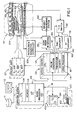
- Fig. 1 there is shown the major components of a preferred MRI system which incorporates the present invention.
- the operation of the system is controlled from an operator console 100 which includes a keyboard and control panel 102 and a display 104.
- the console 100 communicates through a link 116 with a separate computer system 107 that enables an operator to control the production and display of images on the screen 104.
- the computer system 107 includes a number of modules which communicate with each other through a backplane. These include an image processor module 106, a CPU module 108 and a memory module 113, known in the art as a frame buffer for storing image data arrays.
- the computer system 107 is linked to a disk storage 111 and a tape drive 112 for storage of image data and programs, and it communicates with a separate system control 122 through a high speed serial link 115.
- the system control 122 includes a set of modules connected together by a backplane. These include a CPU module 119 and a pulse generator module 121 which connects to the operator console 100 through a serial link 125. It is through this link 125 that the system control 122 receives commands from the operator which indicate the scan sequence that is to be performed.
- the pulse generator module 121 operates the system components to carry out the desired scan sequence.
- a library of pulse sequences are stored by the system control 122 and these may be selected by the operator, who enters specific scan parameters to form the prescribed scan sequence.
- These selectable pulse sequences include a set of customized spatial saturation sequences which may be selected and interleaved with the prescribed imaging pulse sequence.
- the pulse generator module 121 produces data which indicates the timing, strength and shape of the RF pulses which are to be produced, and the timing of and length of the data acquisition window.
- the pulse generator module 121 connects to a set of gradient amplifiers 127, to indicate the timing and shape of the gradient pulses to be produced during the scan.
- the pulse generator module 121 also receives patient data from a physiological acquisition controller 129 that receives signals from a number of different sensors connected to the patient, such as ECG signals from electrodes or respiratory signals from a bellows.
- the pulse generator module 121 connects to a scan room interface circuit 133 which receives signals from various sensors associated with the condition of the patient and the magnet system. It is also through the scan room interface circuit 133 that a patient positioning system 134 receives commands to move the patient to the desired position for the scan.
- the gradient waveforms produced by the pulse generator module 121 are applied to a gradient amplifier system 127 comprised of G x , G y and G z amplifiers.
- Each gradient amplifier excites a corresponding gradient coil in an assembly generally designated 139 to produce the magnetic field gradients used for position encoding acquired signals.
- the gradient coil assembly 139 forms part of a magnet assembly 141 which includes a polarizing magnet 140 and a whole-body RF coil 152.
- a transceiver module 150 in the system control 122 produces pulses which are amplified by an RF amplifier 151 and coupled to the RF coil 152 by a transmit/receive switch 154.
- the resulting signals radiated by the excited nuclei in the patient may be sensed by the same RF coil 152 and coupled through the transmit/receive switch 154 to a preamplifier 153.
- the amplified NMR signals are demodulated, filtered, and digitized in the receiver section of the transceiver 150.
- the transmit/receive switch 154 is controlled by a signal from the pulse generator module 121 to electrically connect the RF amplifier 151 to the coil 152 during the transmit mode and to connect the preamplifier 153 during the receive mode.
- the transmit/receive switch 154 also enables a separate RF coil (for example, a head coil or surface coil) to be used in either the transmit or receive mode.
- the NMR signals picked up by the RF coil 152 are digitized by the transceiver module 150 and transferred to a memory module 160 in the system control 122.
- an array processor 161 operates to Fourier transform the data into an array of image data.
- This image data is conveyed through the serial link 115 to the computer system 107 where it is stored in the disk memory 111.
- this image data may be archived on the tape drive 112, or it may be further processed by the image processor 106 and conveyed to the operator console 100 and presented on the display 104.
- the MRI system performs a series of pulse sequences under the direction of the pulse generator 121.
- the prescribed imaging pulse sequence directs the operation of the transceiver 150 to produce RF pulses and receive resulting NMR signals, and it directs the gradient system 127 to produce the required gradient fields G x , G y and G z .
- the prescribed imaging pulse sequence directs the acquisition of NMR data that will enable an image of the FOV 14 to be reconstructed.
- the size, shape and orientation of the FOV 14 is determined by the scan parameters of the particular prescribed imaging pulse sequence used during the scan.
- the present invention relates to a customized spatial saturation pulse sequence that may be interleaved with the prescribed imaging pulse sequence during the performance of a scan.
- This spatial saturation pulse sequence begins with a selective RF pulse 200 having a flip angle ⁇ which is applied in the presence of a slice select gradient pulse 202.
- the slice select gradient 202 has a strength sufficient to excite a slice, or slab, of spins at a desired location along the slice select gradient axis.
- the frequency bandwidth of the RF pulse 200 determines the thickness of the saturation slice or slab in which spin longitudinal magnetization is suppressed.
- the RF pulse employed in conventional spatial saturation pulse sequences has a flip angle of 90° and a frequency bandwidth of approximately 1 kHz at 1.5 Tesla.
- the frequency bandwidth of the RF pulse 200 may range from 5 to 10 kHz and the nominal flip angle ranges from 120° to 180°.
- a quadratic phase RF pulse is used for the RF pulse 200.
- the resulting transverse magnetization is dephased by a set of spoiler gradient pulses 208, 210 and 212 along the respective imaging gradient axes.
- this dephasing insures that no net NMR signal is produced by the excited spins during the subsequent imaging pulse sequence.
- Three spoiler gradient pulses 208, 210 and 212 are employed because their linearity, and hence effectiveness of a single gradient outside the DSV 10 is questionable. By applying spoiler gradient pulses along all three axes, the probability that at least one of the gradient fields will be of sufficient magnitude at each location inside the excited slice is substantially increased.
- the scan parameters for a set of customized spatial saturation pulse sequences such as that shown in Fig. 3 are stored in the MRI system. These are customized in the sense that each is tailored for use in a specific region around the DSV 10 and each is tailored to suppress spin signals in that region. Referring to Fig. 2, for example, customized spatial saturation sequences may be tailored to suppress spins in regions 16 and 17 located to either side of the DSV 10 along the z axis. The operator may employ the custom spatial saturation pulse sequence corresponding to region 17, for example, if artifacts are generated because the upper portion of the patient body resides in system "hot spots".
- Additional customized spatial saturation pulse sequences may also be selected and interleaved with the prescribed imaging pulse sequences if they are needed to suppress image artifacts caused by signals emanating from other regions outside the DSV 10.
- the number of customized spatial saturation pulse sequences used during a scan is kept to a minimum in order to reduce total scan time and patient RF power deposition.
- the set of stored and selectable customized spatial saturation pulse sequences are produced during a calibration process that is performed when the MRI system is first constructed and whenever changes are made to the MRI system that might affect the homogeneity of the polarizing and RF fields or the linearity of the gradient fields.
- This calibration process is illustrated in Fig. 4 and it is performed with a phantom placed in the MRI system.
- the phantom is made of a substance which produces a strong NMR signal when excited, and it is made large enough to occupy all the regions that can potentially generate peripheral signal artifacts outside the DSV 10 (i.e., the system "hot spots").
- the calibration process is an iterative process in which the saturation pulse settings are methodically sequenced through a set of values for each region, or saturation pulse sequence slice location. As indicated above, these regions are located around the DSV 10 along each of the three gradient axes. As indicated at process block 300, one of these regions serves as a starting point and the RF excitation pulse 200 and slice select gradient pulse 202 are set to select the center of this region. An initial slice thickness is also set at process block 302, which in the preferred embodiment, is the thickness of the selected region. The flip angle of the RF excitation pulse is then set at process block 304 and in the preferred embodiment the initial setting is 120°. A loop is then entered at 306 in which an image is acquired at 308 and reconstructed at 310. The nominal flip angle is incremented at process block 312 by 10° and the acquisition and reconstruction are repeated. When the flip angle reaches 180°, as determined at decision block 314, this loop 306 is exited.
- the imaging pulse sequence used in this acquisition 308 can be a conventional spin-echo pulse sequence which acquires an image from the entire DSV 10 and surrounding regions including the system hot spots.
- the saturation pulse sequence under test is interleaved with the imaging pulse sequences.
- the phantom is placed in the selected region being tested and the image reveals any NMR signals which are produced.
- the selected spin-echo pulse sequence should produce an accurate image of the phantom.
- parts of the image corresponding to the system hot spots will be much brighter (can be an order of magnitude more intense). Some of this intensity will typically ghost into other regions of the image along the phase encoding axis.
- the optimization process illustrated in Fig. 4 operates to minimize these regions of intense brightness and the ghosts which they produce using an optimal set of spatial saturation pulse sequence parameters. This is done by testing different slice thicknesses as indicated at decision block 316 and process block 318, and by testing different slice locations as indicated at decision block 320 and process block 322.
- the final optimal slice thickness for proper saturation should be large enough to cover the entire region of any hot spots with a comfortable margin, but not so large as to interfere with any desired FOV.
- the system loops back at decision block 320 to test the next slice location as indicated at process block 322.
- the system loops back to process block 302 to test each slice thickness and flip angle at the new slice location.
- the calibration images are examined for each slice location and the optimal slice thickness and flip angle settings are determined.
- the optimal settings are those which best suppress all signals in the reconstructed image including the ghost signals from the system hot spots and which have the minimum slice thickness and minimum flip-angle.
- the optimal settings, or scan parameters, for each saturation region outside the DSV 10 are then stored in the system control memory 160.
- only two saturation regions are defined outside the DSV 10 because with the elongated shape of the human body, only the system hot spots located along the superior and inferior directions from the DSV 10 are likely to produce artifacts.
- the optimal settings for the customized saturation pulse sequence for each of these regions is stored in memory 160. These customized saturation pulse sequences are available to the operator as a tool for suppressing image artifacts emanating from spins located outside the DSV 10.
- One aspect of the invention is the selective implementation of these customized saturation pulse sequences.
- spatial saturation is applied for every image slice or once during every n acquired slices.
- the customized saturation pulse sequences will be applied only when needed to suppress artifacts produced by system hot spots. Such artifacts will not occur in all cases, depending on the location and orientation of the prescribed image slices or volume.
Landscapes
- Physics & Mathematics (AREA)
- Optics & Photonics (AREA)
- Spectroscopy & Molecular Physics (AREA)
- High Energy & Nuclear Physics (AREA)
- Condensed Matter Physics & Semiconductors (AREA)
- General Physics & Mathematics (AREA)
- Magnetic Resonance Imaging Apparatus (AREA)
- Apparatus For Radiation Diagnosis (AREA)
Abstract
Description
- The field of the invention is nuclear magnetic resonance imaging methods and systems. More particularly, the invention relates to the reduction of image artifacts caused by signals produced outside the field of view.
- When a substance such as human tissue is subjected to a uniform magnetic field (polarizing field B0), the individual magnetic moments of the spins in the tissue attempt to align with this polarizing field, but precess about it in random order at their characteristic Larmor frequency. If the substance, or tissue, is subjected to a magnetic field (excitation field B1) which is in the x-y plane and which is near the Larmor frequency, the net aligned moment, Mz, may be rotated, or "tipped", into the x-y plane to produce a net transverse magnetic moment Mt. A signal is emitted by the excited spins after the excitation signal B1 is terminated, this signal may be received and processed to form an image.
- When utilizing these signals to produce images, magnetic field gradients (Gx Gy and Gz) are employed. Typically, the region to be imaged is scanned by a sequence of measurement cycles in which these gradients vary according to the particular localization method being used. The resulting set of received NMR signals are digitized and processed to reconstruct the image using one of many well known reconstruction techniques.
- To accurately excite spins and resolve the locations of the resulting NMR signals the polarizing magnetic field B0 must be highly homogeneous and the imaging gradient fields Gx, Gy and Gz must be highly linear. Numerous structures and methods are known in the art to accomplish this in commercial MRI system, and the region where these fields meet the requirements is referred to as the designed spherical volume ("DSV"). The DSV may range for example, from a diameter of 40 to 48 cm. Outside the DSV, the polarizing magnetic field B0 can become very inhomogeneous and the imaging gradients Gx, Gy and Gz can become highly nonlinear. They are also very poorly controlled in these outer regions.
- Referring particularly to Fig. 2, the DSV of a typical MRI system is indicated by dashed
line 10 and a subject to be scanned 12 is placed in theDSV 10. A field of view (FOV) from which accurate NMR data is acquired to reconstruct an image is indicated bydotted lines 14. Portions of thesubject 12 are outside theDSV 10, and the spins therein are subject to the RF excitation fields and magnetic fields produced by the MRI system while imaging theFOV 14. The NMR signals produced by spins located outside the DSV 10 can produce image artifacts. These image artifacts from outside the DSV 10 can be aliased into the reconstructed image because of thelimited imaging FOV 14, they can be depicted in theFOV 14 due to system imperfections, or they can also be ghosted into the image because of the data inconsistency. - Methods and apparatus are known to reduce these artifacts. One solution is to increase the
imaging FOV 14 to reduce aliasing. Hardware solutions include design of gradient coils with a larger linear region or RF transmit coils which significantly reduce RF excitation of spins outside theDSV 10. These are costly solutions which require major system changes. - Another well known method for suppressing artifact-producing signals emanating from spins located outside the
FOV 14 is to interleave spatial saturation pulse sequences with the imaging pulse sequences. As described in U.S. Pat. No. 4,715,383, a spatial saturation pulse sequence suppresses the longitudinal magnetization of the spins in a selected slice or slab outside theFOV 14 by applying a selective RF excitation pulse in the presence of a slice select gradient to excite spins in the selected slice. A spoiler gradient is then applied to dephase the resulting transverse magnetization. Before the longitudinal magnetization in the excited slice can recover, imaging data is acquired from theFOV 14. Because the longitudinal magnetization in the excited slice is suppressed, very little artifact producing signal can be produced in the presaturated slices during the subsequent imaging pulse sequence. - The effectiveness of the spatial saturation method depends on homogeneous B0 and B1 fields and linear gradient fields in the regions outside the
FOV 14 to accurately locate the spatial saturation slice and adequately suppress the spin signals therein. Since the regions outside theDSV 10 do not necessarily satisfy these conditions, the spatial saturation method can be ineffective on any given MRI system in any given location depending on the peculiarities of its fields outside theDSV 10. - The present invention is a method and apparatus for reducing image artifacts caused by signals emanating from outside the DSV. More specifically, it includes the development of a set of spatial saturation pulse sequences which are customized for each MRI system using a calibration method that produces optimal spatial saturation pulse sequence scan parameters for corresponding regions outside the DSV. The RF excitation pulse flip-angle, the slice thickness and the slice location are optimized to suppress signals from specific regions outside the DSV. These customized spatial saturation pulse sequences are stored in the MRI system and may be selectively used by clinicitians to suppress signals from these regions when clinically significant image artifacts are produced in prescribed images.
- The invention will now be described in greater detail, by way of example, with reference to the drawings, in which:-
- Fig. 1 is a block diagram of an MRI system which employs the present invention;
- Fig. 2 is a schematic representation of the DSV, FOV regions in the MRI system of Fig. 1;
- Fig. 3 is a graphic representation of a spatial saturation pulse sequence which is customized according to the present invention; and
- Fig. 4 is a flow chart of the calibration process used to develop the customized spatial saturation pulse sequences for the MRI system of Fig. 1.
-
- Referring first to Fig. 1, there is shown the major components of a preferred MRI system which incorporates the present invention. The operation of the system is controlled from an
operator console 100 which includes a keyboard andcontrol panel 102 and adisplay 104. Theconsole 100 communicates through alink 116 with aseparate computer system 107 that enables an operator to control the production and display of images on thescreen 104. Thecomputer system 107 includes a number of modules which communicate with each other through a backplane. These include animage processor module 106, aCPU module 108 and a memory module 113, known in the art as a frame buffer for storing image data arrays. Thecomputer system 107 is linked to a disk storage 111 and atape drive 112 for storage of image data and programs, and it communicates with aseparate system control 122 through a highspeed serial link 115. - The
system control 122 includes a set of modules connected together by a backplane. These include aCPU module 119 and apulse generator module 121 which connects to theoperator console 100 through aserial link 125. It is through thislink 125 that thesystem control 122 receives commands from the operator which indicate the scan sequence that is to be performed. Thepulse generator module 121 operates the system components to carry out the desired scan sequence. A library of pulse sequences are stored by thesystem control 122 and these may be selected by the operator, who enters specific scan parameters to form the prescribed scan sequence. These selectable pulse sequences include a set of customized spatial saturation sequences which may be selected and interleaved with the prescribed imaging pulse sequence. In response, thepulse generator module 121 produces data which indicates the timing, strength and shape of the RF pulses which are to be produced, and the timing of and length of the data acquisition window. Thepulse generator module 121 connects to a set ofgradient amplifiers 127, to indicate the timing and shape of the gradient pulses to be produced during the scan. Thepulse generator module 121 also receives patient data from aphysiological acquisition controller 129 that receives signals from a number of different sensors connected to the patient, such as ECG signals from electrodes or respiratory signals from a bellows. And finally, thepulse generator module 121 connects to a scanroom interface circuit 133 which receives signals from various sensors associated with the condition of the patient and the magnet system. It is also through the scanroom interface circuit 133 that apatient positioning system 134 receives commands to move the patient to the desired position for the scan. - The gradient waveforms produced by the
pulse generator module 121 are applied to agradient amplifier system 127 comprised of Gx, Gy and Gz amplifiers. Each gradient amplifier excites a corresponding gradient coil in an assembly generally designated 139 to produce the magnetic field gradients used for position encoding acquired signals. Thegradient coil assembly 139 forms part of amagnet assembly 141 which includes a polarizing magnet 140 and a whole-body RF coil 152. Atransceiver module 150 in thesystem control 122 produces pulses which are amplified by anRF amplifier 151 and coupled to the RF coil 152 by a transmit/receiveswitch 154. The resulting signals radiated by the excited nuclei in the patient may be sensed by the same RF coil 152 and coupled through the transmit/receiveswitch 154 to apreamplifier 153. The amplified NMR signals are demodulated, filtered, and digitized in the receiver section of thetransceiver 150. The transmit/receive switch 154 is controlled by a signal from thepulse generator module 121 to electrically connect theRF amplifier 151 to the coil 152 during the transmit mode and to connect thepreamplifier 153 during the receive mode. The transmit/receiveswitch 154 also enables a separate RF coil (for example, a head coil or surface coil) to be used in either the transmit or receive mode. - The NMR signals picked up by the RF coil 152 are digitized by the
transceiver module 150 and transferred to amemory module 160 in thesystem control 122. When the scan is completed and an entire array of data has been acquired in thememory module 160, anarray processor 161 operates to Fourier transform the data into an array of image data. This image data is conveyed through theserial link 115 to thecomputer system 107 where it is stored in the disk memory 111. In response to commands received from theoperator console 100, this image data may be archived on thetape drive 112, or it may be further processed by theimage processor 106 and conveyed to theoperator console 100 and presented on thedisplay 104. - To acquire an image, the MRI system performs a series of pulse sequences under the direction of the
pulse generator 121. There are many imaging pulse sequences known in the art and the present invention may be used with any of them. The prescribed imaging pulse sequence directs the operation of thetransceiver 150 to produce RF pulses and receive resulting NMR signals, and it directs thegradient system 127 to produce the required gradient fields Gx, Gy and Gz. As shown in Fig. 2, the prescribed imaging pulse sequence directs the acquisition of NMR data that will enable an image of theFOV 14 to be reconstructed. The size, shape and orientation of theFOV 14 is determined by the scan parameters of the particular prescribed imaging pulse sequence used during the scan. - Referring particularly to Fig. 3, the present invention relates to a customized spatial saturation pulse sequence that may be interleaved with the prescribed imaging pulse sequence during the performance of a scan. This spatial saturation pulse sequence begins with a
selective RF pulse 200 having a flip angle α which is applied in the presence of a sliceselect gradient pulse 202. The sliceselect gradient 202 has a strength sufficient to excite a slice, or slab, of spins at a desired location along the slice select gradient axis. The frequency bandwidth of theRF pulse 200 determines the thickness of the saturation slice or slab in which spin longitudinal magnetization is suppressed. - The RF pulse employed in conventional spatial saturation pulse sequences has a flip angle of 90° and a frequency bandwidth of approximately 1 kHz at 1.5 Tesla. In the preferred embodiment of the present invention the frequency bandwidth of the
RF pulse 200 may range from 5 to 10 kHz and the nominal flip angle ranges from 120° to 180°. In order to achieve the desired high bandwidth, a quadratic phase RF pulse is used for theRF pulse 200. These features enable the selected slice or slab to saturate spin magnetization in a well defined region even though there may be a significant B0 field inhomogeneity outside theDSV 10. - Referring still to Fig. 3, after a slice or slab of spin magnetization has been excited by the
RF pulse 200, the resulting transverse magnetization is dephased by a set ofspoiler gradient pulses spoiler gradient pulses DSV 10 is questionable. By applying spoiler gradient pulses along all three axes, the probability that at least one of the gradient fields will be of sufficient magnitude at each location inside the excited slice is substantially increased. - The scan parameters for a set of customized spatial saturation pulse sequences such as that shown in Fig. 3 are stored in the MRI system. These are customized in the sense that each is tailored for use in a specific region around the
DSV 10 and each is tailored to suppress spin signals in that region. Referring to Fig. 2, for example, customized spatial saturation sequences may be tailored to suppress spins inregions DSV 10 along the z axis. The operator may employ the custom spatial saturation pulse sequence corresponding toregion 17, for example, if artifacts are generated because the upper portion of the patient body resides in system "hot spots". Additional customized spatial saturation pulse sequences may also be selected and interleaved with the prescribed imaging pulse sequences if they are needed to suppress image artifacts caused by signals emanating from other regions outside theDSV 10. As a general rule, the number of customized spatial saturation pulse sequences used during a scan is kept to a minimum in order to reduce total scan time and patient RF power deposition. - The set of stored and selectable customized spatial saturation pulse sequences are produced during a calibration process that is performed when the MRI system is first constructed and whenever changes are made to the MRI system that might affect the homogeneity of the polarizing and RF fields or the linearity of the gradient fields. This calibration process is illustrated in Fig. 4 and it is performed with a phantom placed in the MRI system. The phantom is made of a substance which produces a strong NMR signal when excited, and it is made large enough to occupy all the regions that can potentially generate peripheral signal artifacts outside the DSV 10 (i.e., the system "hot spots").
- Referring particularly to Fig. 4, the calibration process is an iterative process in which the saturation pulse settings are methodically sequenced through a set of values for each region, or saturation pulse sequence slice location. As indicated above, these regions are located around the
DSV 10 along each of the three gradient axes. As indicated atprocess block 300, one of these regions serves as a starting point and theRF excitation pulse 200 and sliceselect gradient pulse 202 are set to select the center of this region. An initial slice thickness is also set atprocess block 302, which in the preferred embodiment, is the thickness of the selected region. The flip angle of the RF excitation pulse is then set atprocess block 304 and in the preferred embodiment the initial setting is 120°. A loop is then entered at 306 in which an image is acquired at 308 and reconstructed at 310. The nominal flip angle is incremented at process block 312 by 10° and the acquisition and reconstruction are repeated. When the flip angle reaches 180°, as determined atdecision block 314, this loop 306 is exited. - The imaging pulse sequence used in this
acquisition 308 can be a conventional spin-echo pulse sequence which acquires an image from theentire DSV 10 and surrounding regions including the system hot spots. The saturation pulse sequence under test is interleaved with the imaging pulse sequences. The phantom is placed in the selected region being tested and the image reveals any NMR signals which are produced. When the saturation pulses are not applied the selected spin-echo pulse sequence should produce an accurate image of the phantom. However, parts of the image corresponding to the system hot spots will be much brighter (can be an order of magnitude more intense). Some of this intensity will typically ghost into other regions of the image along the phase encoding axis. - The optimization process illustrated in Fig. 4 operates to minimize these regions of intense brightness and the ghosts which they produce using an optimal set of spatial saturation pulse sequence parameters. This is done by testing different slice thicknesses as indicated at
decision block 316 and process block 318, and by testing different slice locations as indicated atdecision block 320 andprocess block 322. The final optimal slice thickness for proper saturation should be large enough to cover the entire region of any hot spots with a comfortable margin, but not so large as to interfere with any desired FOV. - The system loops back at
decision block 320 to test the next slice location as indicated atprocess block 322. The system loops back to process block 302 to test each slice thickness and flip angle at the new slice location. When all of the slice locations have been fully tested as determined atdecision block 320, the collection of calibration images is complete. - As indicated at
process block 324, the calibration images are examined for each slice location and the optimal slice thickness and flip angle settings are determined. The optimal settings are those which best suppress all signals in the reconstructed image including the ghost signals from the system hot spots and which have the minimum slice thickness and minimum flip-angle. As indicated atprocess block 326, the optimal settings, or scan parameters, for each saturation region outside theDSV 10 are then stored in thesystem control memory 160. - In the preferred embodiment only two saturation regions are defined outside the
DSV 10 because with the elongated shape of the human body, only the system hot spots located along the superior and inferior directions from theDSV 10 are likely to produce artifacts. The optimal settings for the customized saturation pulse sequence for each of these regions is stored inmemory 160. These customized saturation pulse sequences are available to the operator as a tool for suppressing image artifacts emanating from spins located outside theDSV 10. - One aspect of the invention is the selective implementation of these customized saturation pulse sequences. In a conventional implementation, spatial saturation is applied for every image slice or once during every n acquired slices. In order to minimize the gradient field and RF field demand on the system, as well as to reduce the RF heating deposition in the imaged subject, it is contemplated that the customized saturation pulse sequences will be applied only when needed to suppress artifacts produced by system hot spots. Such artifacts will not occur in all cases, depending on the location and orientation of the prescribed image slices or volume.
- For the sake of good order, various aspects of the invention are set out in the following clauses:-
- 1. A magnetic resonance imaging (MRI) system, which comprises:
- a polarizing magnet (140) for producing a homogeneous polarizing field in a designed volume (10);
- an RF system (150, 151, 152) for producing a homogeneous radio frequency field in the designed volume (10);
- a gradient system (127, 139) for producing linear magnetic field gradients in the designed volume (10);
- a pulse generator (121) which operates in response to a pulse sequence to control the operation of the RF system and the gradient system to acquire image data from a subject positioned in the designed volume (10); and
- a memory (160) for storing a set of custom spatial saturation pulse sequences which may be selected to operate the pulse generator (121), each stored custom spatial saturation pulse sequence corresponding to a region (16, 17) outside the designed volume (10) and being operable when selected to direct the MRI system to suppress NMR signals emanating from the corresponding region (16, 17).
- 2. The MRI system as recited in clause 1 in which the memory (160) includes a location for storing a flip angle for each custom spatial saturation pulse sequence.
- 3. The MRI system as recited in clause 2 in which the memory (160) also includes a location for storing a slice thickness for each custom spatial saturation pulse sequence.
- 4. The MRI system as recited in clause 1 in which the memory (160) includes a location for storing a slice thickness for each custom spatial saturation pulse sequence.
- 5. A method for producing an image with a magnetic resonance imaging
(MRI) system, the steps comprising:
- a) selecting from a stored library of imaging pulse sequences one of the imaging pulse sequences;
- b) entering scan parameters for the selected imaging pulse sequence that prescribe the image acquisition to be performed by the MRI system, the scan parameters including information which designates the field of view (14) of the acquired image within a designed volume (10);
- c) selecting from a set of stored customized spatial saturation pulse sequences a customized spatial saturation pulse sequence to be interleaved with the selected imaging pulse sequence, each customized spatial saturation pulse sequence corresponding to one of a plurality of regions (16, 17) substantially outside the designed volume (10) in which artifact producing signals are to be suppressed;
- d) acquiring image data with the MRI system using the selected imaging pulse sequence interleaved with the selected customized spatial saturation pulse sequence; and
- e) reconstructing the image from the acquired image data.
- 6. The method as recited in clause 5 in which the selected, customized
spatial saturation pulse sequence directs the MRI system to perform the steps
comprising:
- i) producing a slice select gradient field pulse (202);
- ii) producing an RF excitation field pulse (200) in combination with the slice select gradient field pulse (202) to produce transverse magnetization in the region (16, 17) corresponding to the selected customized spatial saturation pulse sequence and to suppress longitudinal magnetization in said region (16, 17); and
- iii) producing a spoiler gradient field pulse (208, 210, 212) to dephase the transverse magnetization.
- 7. The method as recited in clause 6 in which the RF excitation field pulse (200) has a flip angle from 120° to 180°.
- 8. The method as recited in clause 6 in which the RF excitation field pulse (200) has a frequency bandwidth from 5 kHz to 10 kHz.
- 9. The method as recited in clause 6 which includes producing a plurality of spoiler gradient field pulses (208, 210, 212) in step iii) along a corresponding plurality of gradient field axes.
- 10. The method as recited in clause 6 in which the RF excitation field pulse (200) and the slice select gradient field pulse (202) cooperate to produce transverse magnetization and to suppress longitudinal magnetization in a slice thickness that encompasses MRI system hot spots.
- 11. The method as recited in clause 5 in which step c) includes:
- i) selecting an additional stored customized spatial saturation
pulse sequence;
and step d) includes: - ii) interleaving the additional selected customized spatial saturation pulse sequence with the selected imaging pulse sequence.
- 12. A method for producing a customized spatial saturation pulse
sequence for use on a magnetic resonance imaging (MRI) system to
suppress NMR signals emanating from a region (16, 17) located substantially
outside a designed spherical volume (10) (DSV) in the MRI system, the steps
comprising:
- a) locating a phantom in the region;
- b) iteratively acquiring and reconstructing a set of images with the MRI system;
- c) interleaving a spatial saturation pulse sequence with imaging pulse sequences used in step b) and changing a flip-angle (312) and a slice thickness scan parameter (318) of the spatial saturation pulse sequence as the set of images are acquired; and
- d) selecting optimal scan parameters (324) to form a spatial saturation pulse sequence that is customized to suppress signals emanating from the region by analyzing the set of images.
- 13. The method as recited in
clause 12 in which the flip-angle is changed over a range of 120° to 180° during the performance of step b). - 14. The method as recited in
clause 12 in which different slice thicknesses are employed and the flip-angle is changed over a range of 120° to 180° for each value of the slice thickness such that images are produced using all combinations of spatial saturation pulse sequence scan parameters. - 15. The method as recited in
clause 12 in which the phantom is located to reside in MRI system hot spots. - 16. The method as recited in clause 15 in which step d) is performed by selecting scan parameters which suppress the signals from the MRI system hot spots.
-
Claims (10)
- A magnetic resonance imaging (MRI) system, which comprises:a polarizing magnet (140) for producing a homogeneous polarizing field in a designed volume (10);an RF system (150, 151, 152) for producing a homogeneous radio frequency field in the designed volume (10);a gradient system (127, 139) for producing linear magnetic field gradients in the designed volume (10); anda pulse generator (121) which operates in response to a pulse sequence to control the operation of the RF system and the gradient system to acquire image data from a subject positioned in the designed volume (10); a memory (160) for storing a set of custom spatial saturation pulse sequences which may be selected to operate the pulse generator (121), each stored custom spatial saturation pulse sequence corresponding to a region (16, 17) outside the designed volume (10) and being operable when selected to direct the MRI system to suppress NMR signals emanating from the corresponding region (16, 17).
- The MRI system as recited in claim 1 in which the memory (160) includes a location for storing a flip angle for each custom spatial saturation pulse sequence.
- The MRI system as recited in claim 2 in which the memory (160) also includes a location for storing a slice thickness for each custom spatial saturation pulse sequence.
- The MRI system as recited in claim 1 in which the memory (160) includes a location for storing a slice thickness for each custom spatial saturation pulse sequence.
- A method for producing an image with a magnetic resonance imaging (MRI) system, the steps comprising:a) selecting from a stored library of imaging pulse sequences one of the imaging pulse sequences;b) entering scan parameters for the selected imaging pulse sequence that prescribe the image acquisition to be performed by the MRI system, the scan parameters including information which designates the field of view (14) of the acquired image within a designed volume (10);c) selecting from a set of stored customized spatial saturation pulse sequences a customized spatial saturation pulse sequence to be interleaved with the selected imaging pulse sequence, each customized spatial saturation pulse sequence corresponding to one of a plurality of regions (16, 17) substantially outside the designed volume (10) in which artifact producing signals are to be suppressed;d) acquiring image data with the MRI system using the selected imaging pulse sequence interleaved with the selected customized spatial saturation pulse sequence; ande) reconstructing the image from the acquired image data.
- The method as recited in claim 5 in which the selected, customized spatial saturation pulse sequence directs the MRI system to perform the steps comprising:i) producing a slice select gradient field pulse (202);ii) producing an RF excitation field pulse (200) in combination with the slice select gradient field pulse (202) to produce transverse magnetization in the region (16, 17) corresponding to the selected customized spatial saturation pulse sequence and to suppress longitudinal magnetization in said region (16, 17); andiii) producing a spoiler gradient field pulse (208, 210, 212) to dephase the transverse magnetization.
- The method as recited in claim 6 in which the RF excitation field pulse (200) has a flip angle from 120° to 180°.
- A method for producing a customized spatial saturation pulse sequence for use on a magnetic resonance imaging (MRI) system to suppress NMR signals emanating from a region (16, 17) located substantially outside a designed spherical volume (10) (DSV) in the MRI system, the steps comprising:a) locating a phantom in the region;b) iteratively acquiring and reconstructing a set of images with the MRI system;c) interleaving a spatial saturation pulse sequence with imaging pulse sequences used in step b) and changing a flip-angle (312) and a slice thickness scan parameter (318) of the spatial saturation pulse sequence as the set of images are acquired; andd) selecting optimal scan parameters (324) to form a spatial saturation pulse sequence that is customized to suppress signals emanating from the region by analyzing the set of images.
- The method as recited in claim 8 in which the flip-angle is changed over a range of 120° to 180° during the performance of step b).
- The method as recited in claim 8 in which different slice thicknesses are employed and the flip-angle is changed over a range of 120° to 180° for each value of the slice thickness such that images are produced using all combinations of spatial saturation pulse sequence scan parameters.
Applications Claiming Priority (2)
| Application Number | Priority Date | Filing Date | Title |
|---|---|---|---|
| US10/059,814 US7054675B2 (en) | 2002-01-30 | 2002-01-30 | Customized spatial saturation pulse sequence for suppression of artifacts in MR images |
| US59814 | 2002-01-30 |
Publications (2)
| Publication Number | Publication Date |
|---|---|
| EP1333295A2 true EP1333295A2 (en) | 2003-08-06 |
| EP1333295A3 EP1333295A3 (en) | 2005-04-06 |
Family
ID=22025433
Family Applications (1)
| Application Number | Title | Priority Date | Filing Date |
|---|---|---|---|
| EP03250501A Withdrawn EP1333295A3 (en) | 2002-01-30 | 2003-01-28 | Customized spatial saturation pulse sequence for suppression of artifacts in MR images |
Country Status (3)
| Country | Link |
|---|---|
| US (1) | US7054675B2 (en) |
| EP (1) | EP1333295A3 (en) |
| JP (1) | JP4222846B2 (en) |
Cited By (1)
| Publication number | Priority date | Publication date | Assignee | Title |
|---|---|---|---|---|
| CN109814057A (en) * | 2017-11-20 | 2019-05-28 | 西门子保健有限责任公司 | For running the method and MR imaging apparatus of MR imaging apparatus |
Families Citing this family (15)
| Publication number | Priority date | Publication date | Assignee | Title |
|---|---|---|---|---|
| AU2003253151A1 (en) * | 2002-09-18 | 2004-04-08 | Koninklijke Philips Electronics N.V. | A method of cyclic magnetic resonance imaging |
| JP4717573B2 (en) * | 2005-09-26 | 2011-07-06 | ジーイー・メディカル・システムズ・グローバル・テクノロジー・カンパニー・エルエルシー | MRI equipment |
| JP5133557B2 (en) * | 2006-12-13 | 2013-01-30 | ジーイー・メディカル・システムズ・グローバル・テクノロジー・カンパニー・エルエルシー | MRI apparatus, RF coil, and magnetic resonance signal suppressing method |
| US8971992B2 (en) * | 2007-05-07 | 2015-03-03 | Kabushiki Kaisha Toshiba | Magnetic resonance imaging apparatus and control method thereof |
| JP5127308B2 (en) * | 2007-06-06 | 2013-01-23 | 株式会社日立メディコ | Magnetic resonance imaging system |
| US8384380B2 (en) * | 2007-07-02 | 2013-02-26 | Hitachi Medical Corporation | Magnetic resonance imaging apparatus and magnetic resonance imaging method |
| DE102007030624B4 (en) * | 2007-07-02 | 2018-01-25 | Siemens Healthcare Gmbh | Method, computer program and magnetic resonance device for the location-dependent adjustment of system parameters of a magnetic resonance device |
| JP2009056072A (en) * | 2007-08-31 | 2009-03-19 | Ge Medical Systems Global Technology Co Llc | Magnetic resonance imaging apparatus |
| US7683621B1 (en) | 2008-09-08 | 2010-03-23 | General Electric Company | System and method for tissue point tracking using magnetic resonance imaging |
| US9788753B2 (en) * | 2009-02-26 | 2017-10-17 | Ramot At Tel-Aviv University Ltd. | Method and system for characterizing cortical structures |
| US8305077B2 (en) * | 2009-07-06 | 2012-11-06 | University Of Utah Research Foundation | Phase sensitive radio frequency mapping for magnetic resonance imaging |
| WO2011050348A2 (en) * | 2009-10-24 | 2011-04-28 | Stc.Unm | System and methods for automatic placement of spatial supression regions in mri and mrsi |
| US9739861B2 (en) | 2012-04-19 | 2017-08-22 | University Of Southern California | Method for reduced field of view MRI in an inhomogeneous field with rapid outer volume suppression |
| US9569863B2 (en) * | 2012-08-06 | 2017-02-14 | Siemens Healthcare Gmbh | System for accelerated segmented MR image data acquisition |
| JP6580818B2 (en) | 2014-09-30 | 2019-09-25 | キヤノンメディカルシステムズ株式会社 | Magnetic resonance imaging system |
Citations (6)
| Publication number | Priority date | Publication date | Assignee | Title |
|---|---|---|---|---|
| US4715383A (en) | 1986-11-10 | 1987-12-29 | General Electric Company | Method for reducing artifacts in NMR images |
| EP0265955A2 (en) | 1986-10-29 | 1988-05-04 | Hitachi Medical Corporation | Nuclear magnetic resonance imaging method |
| JPH0241136A (en) | 1988-07-29 | 1990-02-09 | Yokogawa Medical Syst Ltd | Imaging method of nuclear magnetic resonance image diagnostic apparatus |
| JPH0475638A (en) | 1990-07-19 | 1992-03-10 | Hitachi Medical Corp | Magnetic resonance imaging device |
| JPH04158840A (en) | 1990-10-23 | 1992-06-01 | Hitachi Medical Corp | Magnetic resonance imaging apparatus |
| JPH11225992A (en) | 1998-02-19 | 1999-08-24 | Toshiba Corp | Presaturation width setting method and magnetic resonance imaging apparatus |
Family Cites Families (4)
| Publication number | Priority date | Publication date | Assignee | Title |
|---|---|---|---|---|
| US5664568A (en) * | 1995-08-08 | 1997-09-09 | Picker International, Inc. | Split-top, neck and head vascular array for magnetic resonance imaging |
| US5657757A (en) * | 1995-08-17 | 1997-08-19 | General Electric Company | Interleaved MR spectroscopy and imaging with dynamically changing acquisition parameters |
| JP4537542B2 (en) | 2000-06-30 | 2010-09-01 | 株式会社東芝 | Magnetic resonance diagnostic equipment |
| US6486668B1 (en) * | 2000-11-20 | 2002-11-26 | Ge Medical Systems Global Technology Company, Llc | Preparatory pulse sequence for suppression of artifacts in MR images |
-
2002
- 2002-01-30 US US10/059,814 patent/US7054675B2/en not_active Expired - Fee Related
-
2003
- 2003-01-28 EP EP03250501A patent/EP1333295A3/en not_active Withdrawn
- 2003-01-30 JP JP2003021607A patent/JP4222846B2/en not_active Expired - Fee Related
Patent Citations (7)
| Publication number | Priority date | Publication date | Assignee | Title |
|---|---|---|---|---|
| EP0265955A2 (en) | 1986-10-29 | 1988-05-04 | Hitachi Medical Corporation | Nuclear magnetic resonance imaging method |
| US4715383A (en) | 1986-11-10 | 1987-12-29 | General Electric Company | Method for reducing artifacts in NMR images |
| US4715383B1 (en) | 1986-11-10 | 1995-10-31 | Mayo Medical Resources | Method for reducing artifacts in NMR images |
| JPH0241136A (en) | 1988-07-29 | 1990-02-09 | Yokogawa Medical Syst Ltd | Imaging method of nuclear magnetic resonance image diagnostic apparatus |
| JPH0475638A (en) | 1990-07-19 | 1992-03-10 | Hitachi Medical Corp | Magnetic resonance imaging device |
| JPH04158840A (en) | 1990-10-23 | 1992-06-01 | Hitachi Medical Corp | Magnetic resonance imaging apparatus |
| JPH11225992A (en) | 1998-02-19 | 1999-08-24 | Toshiba Corp | Presaturation width setting method and magnetic resonance imaging apparatus |
Cited By (1)
| Publication number | Priority date | Publication date | Assignee | Title |
|---|---|---|---|---|
| CN109814057A (en) * | 2017-11-20 | 2019-05-28 | 西门子保健有限责任公司 | For running the method and MR imaging apparatus of MR imaging apparatus |
Also Published As
| Publication number | Publication date |
|---|---|
| JP4222846B2 (en) | 2009-02-12 |
| JP2003230549A (en) | 2003-08-19 |
| US20030144587A1 (en) | 2003-07-31 |
| EP1333295A3 (en) | 2005-04-06 |
| US7054675B2 (en) | 2006-05-30 |
Similar Documents
| Publication | Publication Date | Title |
|---|---|---|
| US6078176A (en) | Fast spin echo pulse sequence for diffusion weighted imaging | |
| US6144874A (en) | Respiratory gating method for MR imaging | |
| US6559642B2 (en) | Calibration method for use with sensitivity encoding MRI acquisition | |
| US5657757A (en) | Interleaved MR spectroscopy and imaging with dynamically changing acquisition parameters | |
| US6134464A (en) | Multi-slice and multi-angle MRI using fast spin echo acquisition | |
| EP0997743A2 (en) | Acquisition of segmented cardiac gated MRI perfusion images | |
| US6486671B1 (en) | MRI image quality improvement using matrix regularization | |
| US7952354B2 (en) | System and method for fast MR imaging of metabolites at selective excitation frequencies | |
| US7054675B2 (en) | Customized spatial saturation pulse sequence for suppression of artifacts in MR images | |
| US6486668B1 (en) | Preparatory pulse sequence for suppression of artifacts in MR images | |
| US7064547B1 (en) | Method and apparatus of M/r imaging with coil calibration data acquisition | |
| WO2005001499A1 (en) | Isotropic imaging of vessels with fat suppression | |
| US7197353B2 (en) | Sensitivity encoding MRI acquisition method | |
| US6469505B1 (en) | Method and apparatus to reduce perturbation field effects in MR images by restricting the region of interest | |
| US6950543B2 (en) | Method and system for image reconstruction | |
| US6487436B1 (en) | Switchable field of view apparatus and method for magnetic resonance imaging | |
| EP1102082A2 (en) | Method and apparatus for reducing image artifacts caused by magnet vibration in an MR imaging system | |
| US7307419B2 (en) | Method and system for spatial-spectral excitation by parallel RF transmission | |
| US7239137B2 (en) | Method and apparatus for fast spin echo (FSE) prescan phase correction | |
| US7358727B1 (en) | Truncated MR imaging with fractional readout FOV useful for breast and spine imaging | |
| US20060132132A1 (en) | Method and system for MR scan acceleration using selective excitation and parallel transmission | |
| EP1102081A2 (en) | Method and apparatus to compensate for image artifacts caused by magnet vibration in an MR imaging system | |
| US6753683B2 (en) | System and method for generating spectra |
Legal Events
| Date | Code | Title | Description |
|---|---|---|---|
| PUAI | Public reference made under article 153(3) epc to a published international application that has entered the european phase |
Free format text: ORIGINAL CODE: 0009012 |
|
| AK | Designated contracting states |
Designated state(s): AT BE BG CH CY CZ DE DK EE ES FI FR GB GR HU IE IT LI LU MC NL PT SE SI SK TR |
|
| AX | Request for extension of the european patent |
Extension state: AL LT LV MK RO |
|
| PUAL | Search report despatched |
Free format text: ORIGINAL CODE: 0009013 |
|
| AK | Designated contracting states |
Kind code of ref document: A3 Designated state(s): AT BE BG CH CY CZ DE DK EE ES FI FR GB GR HU IE IT LI LU MC NL PT SE SI SK TR |
|
| AX | Request for extension of the european patent |
Extension state: AL LT LV MK RO |
|
| 17P | Request for examination filed |
Effective date: 20051006 |
|
| AKX | Designation fees paid |
Designated state(s): DE NL |
|
| 17Q | First examination report despatched |
Effective date: 20091012 |
|
| APBK | Appeal reference recorded |
Free format text: ORIGINAL CODE: EPIDOSNREFNE |
|
| APBN | Date of receipt of notice of appeal recorded |
Free format text: ORIGINAL CODE: EPIDOSNNOA2E |
|
| APBR | Date of receipt of statement of grounds of appeal recorded |
Free format text: ORIGINAL CODE: EPIDOSNNOA3E |
|
| APAV | Appeal reference deleted |
Free format text: ORIGINAL CODE: EPIDOSDREFNE |
|
| APBT | Appeal procedure closed |
Free format text: ORIGINAL CODE: EPIDOSNNOA9E |
|
| STAA | Information on the status of an ep patent application or granted ep patent |
Free format text: STATUS: THE APPLICATION IS DEEMED TO BE WITHDRAWN |
|
| 18D | Application deemed to be withdrawn |
Effective date: 20140801 |