Technical Field
The present invention relates to an object-sensing
device for detecting the presence of an object attached
on a sensing surface, the properties of the object, and
the state of the object, and a control device using the
object-sensing device for changing a control in response
to a detection of the presence of the object by the
object-sensing device.
Background Art
There are various systems for detecting whether or
not an object is present and changing a control in
response to a detection of the presence of the object.
Taking rain drops as an example of the object, a
windshield wiper control device of a windshield of an
automobile has to change a control flexibly in response
to a weather change leading to the start of rainfall.
Development of a rain sensor for detecting whether or
not it is raining is an important issue to enhance the
convenience of a windshield wiper control device.
Hereinafter, a conventional object-sensing device will
be described by taking as an example a conventional rain
sensor for detecting rain drops on a windshield of an
automobile as an object.
In the case of a windshield wiper operated
manually, which commonly is used, drivers have to
recognize that it started to rain and manually switch a
windshield wiper from off to on in view of the running
state of the automobile and a change in the amount of
rain drops attached on the windshield in order to ensure
a necessary view through the windshield for driving the
automobile. In order to reduce the trouble of this
manual switching operation of the windshield wiper, a
rain sensor is provided to detect the presence of an
object such as rain drops on a sensing surface of the
windshield of an automobile so as to determine whether
or not the windshield needs wiping.
As a conventional rain sensor, rain sensors
employing reflected light to detect rain drops are
known. FIG. 23 shows a view simply illustrating the
principle of detecting rain drops by a conventional
reflected light sensing type rain sensor. In FIG. 23,
reference numeral 1000 denotes a windshield of an
automobile. For convenience, the upper space of the
windshield 1000 is inside of the automobile, that is,
the space on the side of a driver, and the lower space
is outside of the automobile. Reference numeral 1010
denotes a light source, 1020 denotes a prism, 1030
denotes a prism for guiding reflected light out from the
inner portion of the windshield, 1040 denotes a lens,
1050 denotes a PD (Photo Detector) as a light-receiving
element, and 1110 denotes a sensing surface. Reference
numeral 1120 denotes a rain drop on the sensing surface.
The light source 1010 irradiates light flux spread
widely enough to cover the entire sensing surface, and
among the light flux, 1130 denotes a locus of the light
incident to a portion in which the rain drop is
attached. Reference numeral 1140 denotes a locus of
light other than the light 1130, which is incident to a
portion of the sensing surface on which the rain drop is
not attached.
In the reflected light sensing type rain sensor, it
is important to adjust the angle at which each component
is provided and the material thereof (in particular, the
refractive index of the material). Describing the basic
principle of detecting rain drops, when a rain drop is
on a sensing surface, incident light escapes to the
outside because a total reflection condition is not
satisfied in the external surface of the windshield
1000. On the other hand, when a rain drop is not
attached on a sensing surface, the total reflection
condition is satisfied in the external surface of the
windshield 1000 and incident light is reflected totally.
The reflected light sensing type rain sensor detects a
difference in the intensity of the reflected light in
these two cases.
Therefore, for the light source 1010 and the prism
1020, the angles and the materials are selected so as to
satisfy the incident condition under which irradiated
light is incident to the inner portion of the windshield
1000. In addition, an angle that allows total
reflection in the sensing surface on the external
surface of the windshield 1000 is selected.
Furthermore, an angle at which light is incident with
respect to the sensing surface 1110 is selected so that
the total reflection condition on the sensing surface is
switched so as to be satisfied or not satisfied in
response to a change of the refractive index due to rain
drops.
For the prism 1030, the material and the angle are
selected so as to satisfy an outgoing condition under
which reflected light can exit from the windshield 1000,
that is, so as not to satisfy the total reflection
condition. For the lens 1040 and the light-receiving
element 1050, the angles and the distance are adjusted
such that light incident to the lens 1040 is focused on
the sensor portion of the light-receiving element 1050.
These components 1010 to 1050 can be provided on
places other than the windshield 1000, for example, on
the hood or the roof. However, since the state of the
windshield 1000 is to be detected, it is preferable to
provide these components in a portion of the windshield
1000. It is also preferable to provide these components
so as not to hinder the view of a driver. For example,
it is preferable to provide these components in a
portion of the windshield in which the view originally
is shielded by a rearview mirror.
The operation of the above-described conventional
reflected light sensing type rain sensor will be
described below. The light flux irradiated from the
light source 1010 is admitted to the internal portion of
the windshield 1000 by the prism 1020 and is incident
onto the entire surface of the sensing surface 1110.
Now, it is assumed that a rain drop 1120 is attached on
the sensing surface 1110. Among the light incident on
the sensing surface 1110, the light 1130 that has been
incident to the portion in which the rain drop 1120 is
attached escapes to the outside because the total
reflection condition is not satisfied because of the
rain drop having a refractive index n of about 1.3 on
the external surface of the windshield 1000, and this
light is not detected by the light-receiving element
1050. On the other hand, among the light incident to
the sensing surface 1110, the light 1140 that has been
incident on a portion to which the rain drop is not
attached is totally reflected because the total
reflection condition is satisfied because of the air
having a refractive index n of about 1 on the external
surface of the windshield 1000. The totally reflected
light is not totally reflected due to the presence of
the prism 1030 on the surface of the windshield 1000
inside of the automobile and exits to the interior of
the automobile. The light that has exited is focused on
the photosensor portion on the light-receiving element
1050 by the lens 1040.
Thus, the amount of light detected by the light-receiving
element 1050 decreases when the rain drop 1120
is present, and the larger the area of the sensing
surface 1110 that is covered with the rain drop 1120
becomes, the less the amount of light detected becomes.
This change of the light amount is detected to determine
the presence of the rain drop on the sensing surface
1110. The above is the principle of the rain drop
detection by the conventional reflected light sensing
type rain sensor.
Each type of a rain sensor is configured so as to
output a rain drop detection signal when a signal change
as described above is detected. The rain drop detection
signal from the rain sensor is input to a control
portion of a windshield wiper, and the windshield wiper
is controlled as desired in response to the input of the
rain drop detection signal.
However, the conventional rain sensor has the
following problems.
A first problem is that although the presence of an
object can be detected with the conventional rain
sensor, the type of the object and the state are not
estimated. The main purpose of the rain sensor is to
control the driving of the wiper that wipes the
windshield 1000, if necessary, and there are some cases
where the driving of the wiper has to be switched in
accordance with the type and the state of an object
attached on the windshield 1000. The conventional rain
sensor cannot estimate the type of the object and the
state thereof, so that it cannot but perform the same
and uniform control.
The object attached on the windshield 1000 is not
necessarily water drops due to rainfall. Various kinds
of objects can be thought of, such as muddy water
scattered during driving and droppings dropped by birds
such as pigeons. The state of the object is varied, and
even when water is attached, various states can be
thought of, such as in the state of fogging on the
windshield, or in the state of frozen ice caused by
temperatures dropping in winter. In the case of muddy
water, there are a state with a large water content and
a dry state with a small water content. Also in the
case of droppings of birds, there are soft droppings and
dry droppings.
It is preferable to switch the driving of the wiper
in accordance with the type and the state of the object
attached on the windshield 1000. For example, when
water is frozen, or when muddy water or droppings of
birds are dry, wiping only with a wiper is not
effective, and what is worse, the device or the
windshield may be damaged. In this case, for example,
it is preferable to drive the wiper while spraying
cleaning liquid.
A second problem is concerned with the precision of
object detection. In the conventional rain sensor, an
absolute value of a signal level of the amount of light
detected by the light-receiving element is analyzed, or
signal levels detected at a constant time interval are
stored, and temporal changes of the signal levels are
analyzed so as to detect the presence of an object on
the sensing surface. The temporal changes of the
detected signal levels are slightly different, depending
on the type of the object and the object state, but it
is not easy to detect such a slight change precisely and
estimate the type of the object and the object state.
Disclosure of Invention
In view of the above-described problems, it is an
object of the present invention to provide an object-sensing
device for not only detecting the presence of an
object on a sensing surface, but also estimating the
kind of the object and further estimating the state
thereof, and a control device for performing control in
accordance with the kind and the state of the object
that are estimated with the object-sensing device.
In order to solve the above problems, a first
object-sensing device of the present invention includes
a light source for total reflection and a light source
for scattering, and an outer surface of a transparent
substrate is used as a sensing surface on which an
incident light admitted into the transparent substrate
from the light source for total reflection is reflected,
and an incident light admitted into the transparent
substrate from the light source for scattering is
irradiated. The light source for total reflection, the
transparent substrate and a light receiver are arranged
such that the reflected light of the light source for
total reflection from the sensing surface can be
received by the light receiver, and the light source for
scattering and the light receiver are arranged such that
scattered light of the light source for scattering from
the sensing surface can be received by the light
receiver. The object-sensing device includes an object
sensor for detecting a change in a signal level from the
light source for total reflection due to an object in a
photo detection signal detected by the light receiver so
as to detect the presence of the object; and a light-scattering-object
sensor for detecting a change in a
signal level from the light source for scattering due to
an object in a photo detection signal detected by the
light receiver so as to detect whether or not the object
is a light scattering object.
With this feature, not only the presence of an
object based on a change in the reflection condition by
the object sensor, but also the presence of a light
scattering object based on a change in the scattering
condition by the light-scattering-object sensor can be
detected, and the kind of the object can be estimated
based on the light scattering properties of the object.
In the first object-sensing device, it is
preferable that the object sensor and the light-scattering-object
sensor receive light from the same
detecting surface.
According to this feature, the sensing surface can
be used as a common surface for the two detectors, so
that the device can be small.
In the first object-sensing device, it is
preferable that the object-sensing device operates while
switching the light source for total reflection and the
light source for scattering.
According to this feature, even if the two
detectors use a common sensing surface, the two
detectors can be controlled easily.
Next, in the first object-sensing device, it is
preferable that when the presence of an object is
detected by the object sensor, and the presence of a
light scattering object is detected by the light-scattering-object
sensor, then the object is estimated
to be a substance having light scattering properties,
and when the presence of an object is detected by the
object sensor, and the presence of a light scattering
object is not detected by the light-scattering-object
sensor, then the object is estimated to be a substance
having light transmission properties. In other words,
it is preferable that when the presence of an object is
detected by the object sensor, and the presence of a
light scattering object is detected by the light-scattering-object
sensor, then the object is estimated
to be muddy water, and when the presence of an object is
detected by the object sensor, and the presence of a
light scattering object is not detected by the light-scattering-object
sensor, then the object is estimated
to be a water drop.
With this feature, it can be estimated whether a
detected object is a substance having light scattering
properties with little light transmission properties,
for example, mud, or a substance having light
transmission properties, for example, a rain drop. This
is because muddy water has light scattering properties,
so that light scattering occurs on the sensing surface,
whereas rain drops are transparent and do not have light
scattering properties, so that light scattering does not
occur on the sensing surface.
In order to solve the above problems, a second
object-sensing device of the present invention includes
two types of light sources for total reflection and
scattering. A portion of an outer surface of a
transparent substrate is used as a sensing surface on
which an incident light admitted into the transparent
substrate from the light source for total reflection is
reflected, and an incident light admitted into the
transparent substrate from the light source for
scattering is irradiated. The object-sensing device
includes an imaging lens for forming an image with each
of the reflected light by the light source for total
reflection and scattered light by the light source for
scattering that are incident from the sensing surface,
and a light-receiving element array. Light from the
imaging lens is received, and a signal pattern in which
photo detection signals from each micro-light-receiving
element are aligned in accordance with an arrangement of
the micro-light-receiving elements is generated for each
light source, and the signal pattern corresponding to an
object state of an object on the sensing surface is
output.
With this feature, not only the presence of an
object based on a change in the reflection condition by
the object sensor, but also the presence of scattering
properties of the object based on a change in the
scattering condition by the light-scattering-object
sensor can be detected, and the kind of the object can
be estimated based on the scattering properties of the
object. With this feature, one kind of signal pattern
(signal waveform) in which photo detection signals
detected from micro-light-receiving elements
corresponding to the sensing surface are aligned in
accordance with the arrangement of the light-receiving
elements can be obtained. This signal pattern is
obtained by joining signal levels obtained from the
sensing surface so as to form a pattern, and a
difference in the state of the object on the sensing
surface is indicated by a relative change between micro-sections
of the signal pattern. The present invention
can estimate, for example, the kind and the state of the
object on the sensing surface by analyzing the relative
change in the signal pattern. Furthermore, since the
relative change between the micro-sections of the signal
pattern is analyzed, the presence of a fine object can
be detected with high precision, and the detection
hardly is affected by a change in the surroundings due
to the temperature characteristics. The resolution of
this signal pattern depends on the light-receiving
elements corresponding to the sensing surface.
It is preferable that the second object-sensing
device includes a light switch for switching irradiation
of the light source for total reflection and irradiation
of the light source for scattering.
With this feature, a signal pattern can be obtained
with the light source for total reflection in
distinction from a signal pattern with the light source
for scattering. It is preferable to switch the light
source for total reflection and the light source for
scattering so as not to be mixed, in particular, when
the light source for total reflection and the light
source for scattering have the same wavelength.
Next, it is preferable that the second object-sensing
device includes an object sensor for detecting
that an object is present when the presence of a pattern
portion in which a signal level drops relative to
neighboring signal levels is detected in the signal
pattern, the object being present on the sensing surface
corresponding to the pattern portion; and a light-scattering-object
sensor for detecting that a light
scattering object is present when the presence of a
pattern portion in which a signal level increases
relative to neighboring signal levels is detected in the
signal pattern, the light scattering object being
present on the sensing surface corresponding to the
pattern portion, and that when the presence of the
object is detected by the object sensor, and the
presence of the light scattering object is detected by
the light-scattering-object sensor, then the object is
estimated to be a substance having light scattering
properties, and when the presence of the object is
detected by the object sensor, and the presence of the
scattering object is not detected by the light-scattering-object
sensor, then the object is estimated
to be a substance having light transmission properties.
With this feature, it can be estimated whether the
detected object has scattering properties with little
light transmission properties or has light transmission
properties.
Furthermore, it is preferable that in the second
object-sensing device, the magnitude of the light
scattering properties of the object is estimated based
on a relative magnitude of a pattern portion exhibiting
a relative increase from neighboring signal levels in
the signal pattern of the scattered light of the light
source for scattering that is detected by the light-scattering-object
sensor.
With this feature, the magnitude of the light
scattering properties of the object can be estimated in
view of a relative change in the signal pattern.
Furthermore, it is preferable that in the second
object-sensing device, the kind and the state of the
object are estimated based on a relative change of a
pattern portion exhibiting a relative increase from
neighboring signal levels in the signal pattern of the
scattered light of the light source for scattering that
is detected by the light-scattering-object sensor.
With this feature, the kind and the state of the
object can be estimated accurately in view of a relative
change in the signal pattern.
Furthermore, in the second object-sensing device,
when the presence of an object is detected by the object
sensor, and the presence of a scattering object is
detected by the light-scattering-object sensor, then the
object can be estimated to be muddy water, and when the
presence of an object is detected by the object sensor,
and the presence of a scattering object is not detected
by the light-scattering-object sensor, then the object
can be estimated to be a water drop.
This is because muddy water has light scattering
properties, so that light scattering occurs in the
sensing surface, whereas rain drops are transparent and
do not have light scattering properties, so that light
scattering does not occur.
Furthermore, in the second object-sensing device,
when the presence of an object is detected by the object
sensor, and the presence of a scattering object is
detected by the light-scattering-object sensor, then the
object can be estimated to be muddy water, and a
relative magnitude of a pattern portion exhibiting a
relative increase of a signal level from neighboring
signal levels in the signal pattern of the scattered
light of the light source for scattering that is
detected by the light-scattering-object sensor is
smaller than a predetermined ratio, then it can be
estimated that the muddy water is dry.
This is because dry mud is in contact with the
sensing surface only at its contact point in a
microscopic view, so that the region in which light
scattering occurs is relatively smaller than in the case
of muddy water and the ratio of the relative magnitude
of the signal drop portion in the signal pattern becomes
small.
Furthermore, in the second object-sensing device,
when in a signal pattern of the reflected light of the
light source for total reflection detected by the object
sensor a signal level drop throughout the signal pattern
is detected, and in a signal pattern of the scattered
light of the light source for scattering detected by the
light-scattering-object sensor a signal level increase
throughout the signal pattern is detected, then the
object can be estimated to be water droplets due to
condensation.
This is because condensed dews are attached so as
to cover the entire sensing surface, and the entire
signal level is changed, and there is not a large
difference on the sensing surface so that the signal
pattern is smooth.
Furthermore, in the second object-sensing device,
when in a signal pattern of the reflected light of the
light source for total reflection detected by the object
sensor, a signal level drops over the signal pattern and
a change in the signal pattern is not smooth, and in a
signal pattern of the scattered light of the light
source for scattering detected by the light-scattering-object
sensor a signal level is increased over the
signal pattern and a change in the signal pattern is not
smooth, then the object can be estimated to be ice due
to freezing.
This is because when ice is present, the ice covers
the entire sensing surface, and the entire signal level
is changed, and a difference in the state on the sensing
surface is created in an irregular manner because of a
complex change of the shape of the surface of ice, so
that irregularity can be seen in the signal pattern.
Next, the object-sensing device of the present
invention described above can be used as a rain sensor
for detecting the presence of an object attached on a
windshield by providing the sensing surface on the
windshield of an automobile. A windshield wiper device
can be configured by using the object-sensing device as
a rain sensor and further including a windshield wiper
driver; and a windshield wiper controller. The
windshield wiper controller changes the control method
of the windshield wiper driver, based on estimation
results with respect to the kind and the state of an
object from the object-estimating portion.
With this feature, a windshield wiper device in
which the wiping control of the wiper is controlled so
as to be appropriate in accordance with the presence,
the kind, and the state of the object on the windshield
can be provided. For example, when rain drops are
detected, the wiper is put in wiping mode. When muddy
water having a water content is detected, also the wiper
is put in wiping mode. When dry mud is detected, also
the wiper is not put in wiping mode but in operation of
spraying washer liquid. When condensed dew (so-called
fogging) is detected on the sensing surface, the wiper
is put in wiping mode. When ice is detected on the
sensing surface, a process appropriate to the state of
the sensing surface is employed, such as start of a
heater for preventing freezing without putting the wiper
in wiping mode or spraying washer liquid.
Brief Description of Drawings
FIG. 1 is a schematic view simply showing an
example of a device configuration of a first object-sensing
device of the present invention.
FIG. 2 is a view illustrating a concept of an
estimation process with respect to an object by an
object-estimating portion 60 when a rain drop is on a
sensing surface 110.
FIG. 3 is a view illustrating the concept of an
estimation process with respect to an object by an
object-estimating portion 60 when muddy water is on a
sensing surface 110.
FIG. 4 is a diagram showing an example of photo
detection signal levels obtained from a light-receiving
element portion 50 of the first object-sensing device of
the present invention.
FIG. 5 is a flowchart showing a process for
estimating the presence of an object, the kind of the
object and the state of the object with the object-estimating
portion 60 of the first object-sensing device
of the present invention.
FIG. 6 is a view illustrating the concept of an
estimation process with respect to an object by the
object-estimating portion 60 when the object in the
state of dry muddy water is on a sensing surface 110.
FIG. 7 is a flowchart showing a process for
estimating the presence of an object, the kind of the
object and the state of the object with an object-estimating
portion 60 of a second object-sensing device
of the present invention according to Embodiment 2.
FIG. 8 is a view showing an estimation of the
presence of an object, the kind of the object and the
state of the object with photo detection signal levels
in an object detection mode and a light scattering
object detection mode of the first object-sensing device
of the present invention.
FIG. 9 is a schematic view simply showing an
example of a device configuration of the second object-sensing
device of the present invention.
FIG. 10A is a schematic view showing the end face
of a light source portion 10a of the second object-sensing
device of the present invention.
FIG. 10B is a view of the light source portion 10
viewed from the front in which an opening portion 14 can
be seen.
FIG. 11 is a schematic view showing an example of
an imaging lens 40a of the second object-sensing device
of the present invention.
FIG. 12 is a schematic view showing an example of a
light-receiving element portion 50a of the second
object-sensing device of the present invention.
FIG. 13 is a signal pattern when the object
detected by the second object-sensing device of the
present invention is a rain drop and muddy water.
FIG. 14 is a flowchart showing a process for
estimating the presence of an object, the kind of the
object and the state of the object with an object-estimating
portion 60a of the second object-sensing
device of the present invention according to Embodiment
3.
FIG. 15 is a signal pattern when the object
detected by the second object-sensing device of the
present invention is muddy water and dry mud.
FIG. 16 is a graph showing examples of signal
patterns when there is no fogging and when there is
fogging because of condensation detected by the second
object-sensing device of the present invention.
FIG. 17 is a flowchart showing a process for
estimating the presence of an object, the kind of the
object and the state of the object with an object-estimating
portion 60a of the second object-sensing
device of the present invention according to Embodiment
5.
FIG. 18 is a graph showing signal patterns when
there is no frozen ice and when there is frozen ice
detected by the second object-sensing device of the
present invention according to Embodiment 6.
FIG. 19 is a view showing an estimation of the
presence of an object, the kind of the object and the
state of the object with photo detection signal levels
in an object detection mode and a light scattering
object detection mode of the second object-sensing
device of the present invention.
FIG. 20 is a block diagram of a windshield wiper
control device using the object-sensing device of the
present invention as a rain sensor.
FIG. 21 is a flowchart showing an example of a flow
of a process operation of the windshield wiper control
device using the object-sensing device of the present
invention as a rain sensor.
FIG. 22 is a basic view showing an example of a
configuration in which the windshield wiper control
device using the object-sensing device of the present
invention as a rain sensor is provided.
FIG. 23 is a basic view illustrating the principle
of rain drop detection with a conventional reflected
light sensing type rain sensor.
Best Mode for Carrying Out the Invention
In Embodiments 1 and 2, an object-sensing device
for estimating an object by the level of a photo
detection signal of an incident light obtained in a
light-receiving element through a sensing surface will
be described as a first object-sensing device of the
present invention.
In Embodiments 3 to 6, an object-sensing device for
estimating an object by using a micro-light-receiving
element array in which a plurality of micro-light-receiving
elements are aligned as the light-receiving
element, and analyzing a signal pattern obtained by
joining photo detection signal levels of an incident
light obtained in each micro-light-receiving element
through a sensing surface will be described as a second
object-sensing device of the present invention.
Furthermore, in Embodiment 7, a windshield wiper
control device using the object-sensing device of the
present invention as a rain sensor will be described.
(Embodiment 1)
The first object-sensing device of the present
invention will be described. An object-sensing device
capable of estimating the presence of an object on a
sensing surface and whether or not the object is a
substance having light scattering properties will be
described as Embodiment 1. In particular, taking as an
example the case where the object is a rain drop and is
muddy water, it is described that the former and the
latter can be distinguished.
The basic principle of the object-sensing device of
Embodiment 1 of the present invention is as follows. A
reflected light from a light source for total reflection
and scattering light from a light source for scattering
light that are irradiated onto a sensing surface are
received by a light receiver, and the levels of photo
detection signals are analyzed so that a change in the
total reflection condition and the scattering condition
on the sensing surface due to the presence, the kind and
the state of the object on the sensing surface is
detected, so that the presence, the kind and the state
of the object are estimated.
The object-sensing device of the present invention
has a configuration, for example, where an object
detection mode using a light source of total reflection
and a light scattering object detection mode using a
light source for scattering, which are described below,
are provided in order to estimate the presence, the kind
and the state of the object on the sensing surface of a
transparent substrate. Alternatively, a configuration
without the object detection mode and only with the
light scattering object detection mode, or a
configuration without the light scattering object
detection mode and only with the object detection mode
can be configured as alternative embodiments.
Herein, the "object detection mode" refers to a
mode for detecting the presence of an object on the
sensing surface of a transparent substrate. The "light
scattering object detection mode" refers to a mode for
detecting whether the object on the sensing surface has
light scattering properties, for example, whether the
object is muddy water or droppings of birds, etc., which
have light scattering properties. In the object-sensing
device of the present invention, the presence of the
object on the sensing surface is detected in the object
detection mode, and when the light scattering properties
are not detected in the light scattering object
detection mode, it is estimated that the object is a
rain drop, etc. that has light transmission properties.
Furthermore, the presence of the object on the sensing
surface is detected in the object detection mode, and
when the light scattering properties are detected in the
light scattering object detection mode, it is estimated
that the object is muddy water, etc. that has light
scattering properties.
FIG. 1 is a simplified schematic view showing an
example of a device configuration of the object-sensing
device of the present invention of Embodiment 1.
In FIG. 1, reference numeral 100 denotes a
windshield 100 as an example of a transparent substrate.
The layer below the windshield 100 is the outside. A
sensing surface 110 is in a predetermined region on a
boundary surface between the windshield 100 and the
outside. Reference numeral 10 denotes a light source
for total reflection, and reference numeral 20 denotes a
light source for scattering. Reference numerals 30a and
30c are prisms. Reference numeral 40 denotes a
condenser lens, and reference numeral 50 denotes a
light-receiving element portion as a light receiver.
Reference numeral 60 denotes an object-estimating
portion. In this example, the light source 10 for total
reflection, the prisms 30a and 30c, the condenser lens
40, and the light-receiving element portion 50
constitute an object sensor. The light source 20 for
scattering, the prism 30c, the condenser lens 40, and
the light-receiving element portion 50 constitute a
light-scattering-object sensor.
The light source 10 for total reflection can
irradiate a directional irradiation light and is
disposed at a position and an angle that allow the
irradiation light to be incident at a predetermined
angle with respect to the sensing surface 110. The
light source for total reflection is adjusted such that
the light emitted from the light source 10 for total
reflection and admitted the windshield 100 via the prism
30a is incident to the sensing surface 110, and the
total reflection condition on the sensing surface is
satisfied when there is no object on the sensing surface
110, as shown in FIG. 1(c), that is, air is in contact.
The prism 30c, the condenser lens 40, and the light-receiving
element portion 50 are adjusted such that the
reflected light that is totally reflected into the
windshield 100 at the sensing surface 110 is emitted
outside the windshield 100 via the prism 30c provided on
the surface of the windshield 100, and is focused on the
light-receiving surface of the light-receiving element
portion 50 by the condenser lens 40. The angles at
which the light source 10 for total reflection and the
above-described components are provided are adjusted
such that the total reflection condition on the sensing
surface 110 is not satisfied when a rain drop (water
content) is in contact as shown in FIG. 1B.
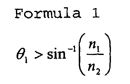
The total reflection condition is represented by
Formula 1.
where n
1 is the refractive index of outside material, n
2
is the refractive index of the
windshield 100, and
1 is
the angle at which the irradiation light is incident to
the sensing surface.
Herein, when n1, which is the refractive index of
air, that is, outside material when no rain drop is
present, as shown in FIG. 1(c), is 1, and n2, which is
the refractive index of the windshield 100, is about
1.51, for example, then Formula 1 results in 41.47° < 1.
Furthermore, when a rain drop is attached as shown in
FIG. 1B, the refractive index of water is about 1.33, so
that 1 < 61.74° is sufficient. In other words, the
light incident angle 1 that switches whether the total
reflection condition shown in Formula 1 on the sensing
surface 110 is satisfied or not satisfied is selected
from the range of 41.47° < 1 < 61.74°. In this example,
the arrangement of the components and the angles at
which the components are provided are adjusted such that
the incident angle to the sensing surface 110 of the
irradiation light from the light source 10 and the
reflection angle therefrom are 47° so as to satisfy the
condition.
Next, the light source 20 for scattering will be
described. The light source 20 for scattering also can
irradiate directional irradiation light and is disposed
at a position and an angle that allow the irradiated
light to be incident at a predetermined angle with
respect to the sensing surface 110. Herein, it is
necessary to detect with high sensitivity the presence
of a light scattered by the object in the light-receiving
element portion 50, which is the light
receiver, so that the configuration is such that the
irradiation light of the light source 20 for scattering
is not incident directly to the light-receiving element
portion 50 when there is no object on the sensing
surface. That is to say, the light source 20 for
scattering is disposed at an angle displaced from the
angle used for the light source 10 for total reflection
so that the totally reflected light at the windshield of
the light source for scattering is not incident directly
on the light-receiving element portion 50. For example,
the incident angle of the irradiation light of the light
source 20 for scattering is set to an angle that does
not satisfy Formula 1, which is the total reflection
condition with respect to the sensing surface 110. In
other words, when n1 is the refractive index of outside
material, n2 is the refractive index of the windshield
100, and 1' is the angle at which the irradiation light
is incident to the sensing surface, the angle 1' is set
to be 41.47° or less, which is the condition that does
not allow the light from the light source for scattering
to be reflected totally. In the example of FIG. 1, 1'
is 0°.
The prism 30a is a prism serving as a medium that
brings the light source 10 for total reflection and the
windshield 100 optically in contact with each other, and
functions to guide the irradiated light from the light
source 10 for total reflection into the windshield 100.
Even if there is no prism serving as a medium that
brings the light source 20 for scattering and the
windshield 100 optically in contact with each other,
light for scattering can be let in, so that this prism
is not necessarily provided, but can be provided.
The prism 30c functions to guide the reflected
light from the light source 10 for total reflection on
the sensing surface 110 and the scattered light from the
light source 20 for scattering out from the windshield
100.
The condenser lens 40 is a lens for focusing light
input from the prism 30c on the light-receiving element
portion 50, which is the light receiver. The present
invention is not limited thereto, and a configuration
without a lens can be used.
The light-receiving element portion 50, which is
the light receiver, is provided with a light-receiving
element for outputting a photo detection signal in
accordance with the amount of light irradiated, and the
angle and the distance of the condenser lens 40 and the
light-receiving element of the light-receiving element
portion 50 are adjusted such that light incident on the
condenser lens 40 is focused on the light-receiving
element of the light-receiving element portion 50.
As described above, the light source 10 for total
reflection, the prisms 30a and 30c, the condenser lens
40, and the light-receiving element portion 50
constitute an object sensor. The light source 20 for
scattering, the prism 30c, the condenser lens 40, and
the light-receiving element portion 50 constitute a
light-scattering-object sensor. In the object-sensing
device of Embodiment 1, the object detection mode in
which the object sensor operates and the light
scattering object detection mode in which the light-scattering-object
sensor operates can be switched by
switching the timing of the light irradiation by the
light source 10 for total reflection and the timing of
the light irradiation by the light source 20 for
scattering. Although a control portion is not shown in
FIG. 1, it is assumed that there is a control portion
provided with functions for controlling the light source
10 for total reflection to be on/off, controlling the
light source 20 for scattering to be on/off, and
notifying the object-estimating portion 60 of an
operation mode, that is, whether or not the mode is the
object detection mode or the light scattering object
detection mode. The object-estimating portion 60 can
serve also as the control portion.
Next, the object-estimating portion 60 will be
described. The object-estimating portion 60 is a
portion for receiving a photo detection signal from the
light-receiving element portion 50 and analyzing the
photo detection signal to estimate the presence of the
object, the kind of the object, and the state of the
object. Since estimation is performed by using a
relative change from the previous photo detection signal
value in each mode in the estimation process, the
object-estimating portion 60 includes a latch portion
for latching the photo detection signal value detected
in the previous detection in each mode. The latch
portion for a photo detection signal in the object
detection mode is referred to as a first latch portion,
and the latch portion for a photo detection signal in
the light scattering object detection mode is referred
to as a second latch portion.
Hereinafter, the process for estimating the
presence of an object, the kind of the object, and the
state of the object with the object-estimating portion
60 will be described. First, the concept of the
estimation process with the object estimation portion 60
will be described with respect to an object when a rain
drop is attached on the sensing surface 110 as the
object.
FIG. 2A is a schematic view showing the manner in
which light is traveling in the object detection mode
when a rain drop is on the sensing surface. In the
object detection mode, light is irradiated from the
light source 10 for total reflection onto the sensing
surface 110, and the light source 20 for scattering is
turned off in the object detection mode. Since the rain
drop is present on the sensing surface 110, as discussed
above, the total reflection condition on the sensing
surface 110 is not satisfied, so that irradiated light
escapes to the outside. In this case, no light is
received by the light-receiving element portion 50. In
principle, "signal level drop" with respect to the
previous signal level is detected in the photo detection
signal received by the object-estimating portion 60 in
the object detection mode.
FIG. 4 is a diagram showing an example of photo
detection signals detected by the light-receiving
element portion 50. The horizontal axis is the time
axis, and the modes are switched alternately. Reference
numeral 401 denotes the object detection mode, 402
denotes the light scattering object detection mode, 403
denotes the object detection mode, and 404 denotes the
light scattering object detection mode. In this manner,
the modes alternate with each other.
FIG. 4A shows an example of a photo detection
signal when the object is a rain drop. As shown in FIG.
4A, the object-estimating portion 60 detects that the
signal level of the latest object detection mode 403 is
lower than that of the previous object detection mode
401 that is latched in the first latch portion. The
reference signal values are not necessarily managed with
absolute values, and the device may start to operate
from a default state and only a relative change from a
signal value captured in the previous object detection
mode may be used for determination. However, it is
preferable to set a threshold value in a ratio in
relative changes and determine that "the signal level is
dropped", only when the signal level is dropped more
than the threshold value in order to eliminate the
influence of noise.
FIG. 2B is a schematic view showing the manner in
which light is traveling in the light scattering object
mode when a rain drop is attached on the sensing
surface. In the light scattering detection mode, light
is irradiated from the light source 20 for scattering
onto the sensing surface 110, and the light source 10
for total reflection is turned off in the light
scattering object detection mode. A rain drop is
present on the sensing surface 110, but the light
scattering properties of the rain drop are poor, so that
light scattering does not occur in principle, and
therefore the irradiated light escapes to the outside.
In this case, the light-receiving element portion 50
receives no light. The photo detection signal received
by the object-estimating portion 60 in the light
scattering object detection mode is in a low level.
In the example of the photo detection signal of
FIG. 4A, the signal level of the latest light scattering
object detection mode 404 is at a low level similarly to
the photo detection signal level of the previous light
scattering object detection mode 402 that is latched in
the second latch portion. However, it is preferable to
set a certain threshold value and determine that "the
signal level is low", only when the signal level does
not exceed the threshold value in order to eliminate the
influence of noise.
The object-estimating portion 60 estimates the
presence of a rain drop, that is, the presence of an
object having poor light scattering properties, when
"signal level drop" is obtained in the object detection
mode and "no change in the signal level (low level is
maintained)" is obtained in the light scattering object
detection mode. FIG. 8 is a diagram showing an
estimation of the presence of the object, the kind of
the object and the state of the object with the photo
detection signal level in the object detection mode and
the light scattering detection mode, and the above
estimation of the rain drop corresponds to the case of
(2) of FIG. 8.
Next is described the concept of an estimation
process with respect to an object by the object-estimating
portion 60 when muddy water is attached on
the sensing surface 110 as the object.
FIG. 3A is a schematic view showing the manner in
which light is traveling in the object detection mode
when muddy water is attached on the sensing surface.
Similarly to the case of FIG. 2A, light is irradiated
from the light source 10 for total reflection onto the
sensing surface 110, and the light source 20 for
scattering is turned off. Since the muddy water 120a is
present on the sensing surface 110, the total reflection
condition on the sensing surface 110 is not satisfied,
so that irradiated light escapes to the outside, or is
scattered or absorbed in the muddy water, and no light
is received by the light-receiving element portion 50.
The object-estimating portion 60 compares and analyzes a
photo detection signal received in the object detection
mode so that "signal level drop" with respect to the
previous signal level can be detected.
FIG. 4B shows an example of a photo detection
signal when the object is muddy water. As in the case
of FIG. 4A, the object-estimating portion 60 detects
that the signal level of the latest object detection
mode 403 is lower than that of the previous object
detection mode 401 that is latched in the first latch
portion.
FIG. 3B is a schematic view showing the manner in
which light is traveling in the light scattering object
mode when muddy water is on the sensing surface. Light
is irradiated from the light source 20 for scattering
onto the sensing surface 110, and the light source 10
for total reflection is turned off. Light from the
light source for scattering falls on the object that is
muddy water 120a. Since the muddy water 120a has light
scattering properties, light scattering occurs.
Therefore, scattered light is released from the muddy
water 120a to the surroundings, and a part thereof is
received by the light-receiving element portion 50 via
the prism 30c and the condenser lens 40. The photo
detection signal received by the object-estimating
portion 60 in the light scattering object detection mode
in principle means "a signal level increase" with
respect to the previous signal level.
In the example of the photo detection signal of
FIG. 4B, the signal level of the latest light scattering
object detection mode 404 is higher than the signal
level in the vicinity of the "0" level of the previous
light scattering object detection mode 402 that is
latched in the second latch portion. However, it is
preferable to set a certain threshold value and
determine that the signal level is increased only when
the signal level exceeds the threshold value in order to
eliminate the influence of noise.
The object-estimating portion 60 estimates the
presence of muddy water, that is, the presence of an
object having light scattering properties, when "signal
level drop" is obtained in the object detection mode and
"signal level increase" is obtained in the light
scattering object detection mode. This estimation
corresponds to the case of (3) of FIG. 8. The process
for estimating the state in which the muddy water has a
water content or the state in which the mud is dry in
distinction from each other will be described later in
Embodiment 2.
The object-estimating portion 60 estimates that the
object has been removed from the sensing surface when
"signal level increase" is detected in the object
detection mode, and estimates that the light scattering
object has been removed from the sensing surface when
"signal level drop" is detected in the light scattering
detection mode. This estimation corresponds to (5) of
FIG. 8.
FIG. 5 is a flowchart showing a process for
estimating the presence of an object, the kind of the
object and the state of the object by the object-estimating
portion 60 of the object-sensing device of
Embodiment 1. In this example, the object-estimating
portion 60 serves also as a control portion for
switching the object detection mode and the light
scattering object detection mode, and is provided with a
latch function to latch a photo detection signal value.
First, the object-estimating portion 60 sets the
operation mode to the object detection mode and sends
out a light irradiation control signal to the light
source 10 for total reflection (operation Op 501). The
light source 10 for total reflection irradiates
irradiation light onto the sensing surface 110, and the
light-receiving element portion 50, which is a light
receiver, receives reflected light from the sensing
surface 110.
Next, the object-estimating portion 60 acquires the
signal level of the light-receiving element portion 50
(operation Op 502). This latest signal level is a
signal based on which the presence of an object is
estimated.
Next, the object-estimating portion 60 acquires the
photo detection signal level detected from the light-receiving
element portion 50 in the previous object
detection mode that is latched in the first latch
portion (operation Op 503). In a process in an initial
state in which there is no previously latched signal,
the signal level of an initial value is set to "low
level".
Next, the object-estimating portion 60 compares and
analyzes the latest signal level of the light-receiving
element portion 50 with the previous signal level of the
light-receiving element portion 50 to detect a change
(operation Op 504).
The object-estimating portion 60 has a threshold
value to determine whether the relative change ratio of
the two signal levels is "signal level drop" or "signal
level increase", and detects either one of three states
of "signal level drop", "signal level increase" and "no
change in the signal level" (operation Op 505).
Next, the first latch portion of the object-estimating
portion 60 latches the latest signal level of
the light-receiving element portion 50 that replaces the
previously latched signal level of the light-receiving
element portion 50 (operation Op 506).
Next, the object-estimating portion 60 sets the
operation mode to the light scattering object detection
mode and sends out a light irradiation control signal to
the light source 20 for scattering (step 507). The
light source 20 for scattering irradiates irradiation
light onto the sensing surface 110, and the light-receiving
element portion 50, which is a light receiver,
receives scattered light from the sensing surface 110.
Next, the object-estimating portion 60 acquires the
signal level of the light-receiving element portion 50
(operation Op 508). This latest signal level is a
signal based on which the presence of a light scattering
object is estimated.
Next, the object-estimating portion 60 acquires the
photo detection signal level detected from the light-receiving
element portion 50 in the previous light
scattering object detection mode that is latched in the
second latch portion (operation Op 509). In a process
in an initial state in which there is no previously
latched signal, the signal level of an initial value is
set to "low level".
Next, the object-estimating portion 60 compares and
analyzes the latest signal level of the light-receiving
element portion 50 with the previous signal level of the
light-receiving element portion 50 to detect a change
(operation Op 510).
The object-estimating portion 60 has a threshold
value to determine whether the relative change ratio of
the two signal levels is "signal level drop" or "signal
level increase", and detects either one of three states
of "signal level drop", "signal level increase" and "no
change in the signal level" (operation Op 511).
Next, the second latch portion of the object-estimating
portion 60 latches the latest signal level of
the light-receiving element portion 50 that replaces the
previously latched signal level of the light-receiving
element portion 50 (operation Op 512).
Next, the object-estimating portion 60 estimates
the presence of an object and the kind of the object
based on the table shown in FIG. 8, in accordance with a
combination of either one of the three states of "signal
level drop", "signal level increase" and "no change in
the signal level" detected in the object detection mode
in operation Op 505 and either one of the three states
of "signal level drop", "signal level increase" and "no
change in the signal level" detected in the light
scattering object detection mode in operation Op 511
(operation Op 513).
According to the above configuration, the four
states of "no object", "rain drops (object having light
transmission properties)", "muddy water (object having
light scattering properties)", and "object removed" as
shown in (1), (2), (3), and (5) of FIG. 8 can be
estimated.
The object-estimating portion 60 outputs an output
signal indicating the above-described estimation results
(operation Op 514), goes back to operation Op 501 when
the process continues (operation Op 515: Y), and ends
the process when the process does not continue
(operation Op 515: N).
In the above description, the object detection mode
comes first, and the light scattering object detection
mode comes after that, but the order can be opposite.
As described above, the object-sensing device of
Embodiment 1 makes it possible to estimate whether or
not an object is present on the sensing surface and
whether or not the object is a substance having light
scattering properties, and in particular, to distinguish
whether the object is a rain drop, muddy water or other
substances as shown as examples.
(Embodiment 2)
An object-sensing device of Embodiment 2 is an
example in which an additional application function is
provided for the process for estimating the kind and the
state of an object in the object-sensing device of
Embodiment 1 of the present invention. In particular,
in this embodiment, it is estimated whether muddy water
is in the state of so-called "muddy water" having a
water content or in a dry state in distinction from each
other when the object is muddy water, for example.
The device configuration and the arrangement of the
components can be the same as in Embodiment 1, so that
the description thereof is omitted. The process of the
object-estimating portion 60 is different.
First, the principle of estimating whether muddy
water is in the state of so-called "muddy water" having
a water content or it is dry mud in distinction from
each other will be described.
The so-called "muddy water" having a water content
will not be described in detail, because it is described
in Embodiment 1. The path of light in the object
detection mode is the same as in FIG. 3A. The signal
level can be detected in the same manner as in FIG. 4A,
and "signal level drop" relative to the previous signal
level is detected. In the light scattering object
detection mode, as shown in FIG. 3B, the presence of
muddy water on the sensing surface 110 causes scattering
on the sensing surface 110, and a part of the scattered
light is captured by the light-receiving element portion
50, which is a light receiver. Thus, "signal level
drop" relative to the previous signal level is detected,
as shown in FIG. 4B.
Then, FIG. 6A is a schematic view showing the
manner in the object detection mode when dry mud is
attached on the sensing surface 110. In the object
detection mode, as in the case of muddy water having a
water content in FIG. 3A, the presence of dry muddy
water on the sensing surface 110 causes a part of
irradiation light to be scattered or absorbed in the
mud, so that the light becomes relatively smaller than
when totally reflected light is received. However, the
scattered light of a part of the irradiation light is
received by the light-receiving element portion 50.
Therefore, a drop in the photo detection signal level is
relatively smaller than in the case of a rain drop.
Thus, the object-estimating portion 60 detects "signal
level drop" relative to the previous signal level.
Then, FIG. 6B is a schematic view showing the
manner in the light scattering object detection mode
when dry mud is attached on the sensing surface 110. In
the light scattering object detection mode, as in the
case of muddy water having a water content in FIG. 3B,
the presence of dry mud 120b on the sensing surface 110
causes light scattering on the sensing surface 110, and
a part of the scattered light is received by the light-receiving
element portion 50, but the amount of the
light received by the light-receiving element portion 50
becomes relatively smaller than in the case of light
scattering by the muddy water having a water content.
The light scattering photo detection level becomes
relatively smaller than in the case of the muddy water
having a water content for the following reason. In the
case of muddy water having a water content, as shown in
FIG. 6(C), the presence of the water content allows
close contact with the sensing surface 110, and light
scattering occurs in the entire area that is in contact
with the muddy water. On the other hand, dry mud is not
in close contact with the sensing surface 110 because of
no water content, as shown in FIG. 6(D), so that light
scattering occurs only at the contact points of mud
particles with respect to the sensing surface.
In principle, the object-sensing device of
Embodiment 2 analyzes the photo detection signal level
of the light-receiving element portion 50 in the light
scattering object detection mode so as to estimate
whether the water content of the object is excessive,
that is, the object is muddy water with a water content
or dry muddy water in distinction from each other. An
example of a process for estimating whether or not the
object has an excessive water content is to compare the
latest signal level of the light-receiving element
portion 50 with the previous signal level of the light-receiving
element portion 50 in the light scattering
object detection mode and estimate whether or not the
water content of the object is excessive based on the
excessiveness of the ratio of "signal level increase"
thereof. In some cases, it is difficult to obtain the
ratio of the signal level increase, for example, because
the previous signal level of the light-receiving element
portion 50 is as small as in the vicinity of "0 level".
In that case, it is possible to estimate whether or not
the water content of the object is excessive based on
the excessiveness of the absolute value of the signal
level, and also possible to determine it, based on both
the relative change and the absolute change.
Thus, the estimating portion 60 estimates that
muddy water with a water content is attached, when it is
determined to be "signal level drop" in the object
sensor operation mode and it is determined to be "signal
level increase (large increase ratio)" in the light-scattering-object
sensor operation mode. The estimating
portion 60 estimates that dry mud is attached, when it
is determined to be "signal level drop" in the object
sensor operation mode and it is determined to be "signal
level increase (small increase ratio)" in the light-scattering-object
sensor operation mode. The degree of
dryness can be estimated in view of the magnitude of the
signal level change.
FIG. 7 is a flowchart showing a process for
estimating the presence of an object, the kind of the
object and the state of the object by the object-estimating
portion 60 of the object-sensing device of
Embodiment 2. In this example, the object-estimating
portion 60 serves also as a control portion for
switching the object detection mode and the light
scattering object detection mode, and is provided with a
latch function to latch a photo detection signal value.
In the estimation process step by the object-estimating
portion 60 of the object-sensing device of
the present invention, the steps after the start can be
the same as the operations Op 501 to Op 506 in the
object detection mode up to the operations Op 507 to Op
509 after moving onto the light scattering object
detection mode, as shown in FIG. 5 of Embodiment 1, so
that these steps are not shown in the flowchart of FIG.
7.
In the operation Op 509, the object-estimating
portion 60 acquires the photo detection signal level
detected from the light-receiving element portion 50 in
the previous light scattering object detection mode that
is latched in the second latch portion, and then
compares and analyzes the latest signal level of the
light-receiving element portion 50 with the previous
signal level of the light-receiving element portion 50
to detect a change (operation Op 701).
The object-estimating portion 60 has a threshold
value to determine whether the relative change ratio of
the two signal levels is "signal level drop" or "signal
level increase", and detects either one of three states
of "signal level drop", "signal level increase" and "no
change in the signal level" (operation Op 702).
In the case of "signal level increase" (operation
Op 703: Y), the object-estimating portion 60 holds the
relative change ratio (operation Op 704).
Next, the second latch portion of the object-estimating
portion 60 latches the latest signal level of
the light-receiving element portion 50 that replaces the
previously latched signal level of the light-receiving
element portion 50 (operation Op 705).
Next, the object-estimating portion 60 estimates
the presence of an object and the kind of the object
based on the table shown in FIG. 8, in accordance with a
combination of either one of the three states of "signal
level drop", "signal level increase" and "no change in
the signal level" detected in the object detection mode
in operation Op 505 and either one of the three states
of "signal level drop", "signal level increase" and "no
change in the signal level" detected in the light
scattering object detection mode in operation Op 702,
and further in view of the relative change ratio in the
case of "signal level increase" held in operation Op 704
(operation Op 706). In this operation Op 706, it is
possible to estimate with the absolute value of the
signal level of the light-receiving element portion 50
in the light scattering object detection mode that is
latched in the second latch portion in the operation Op
705. As shown in (3) and (4) of FIG. 8, in the
estimation that the object is muddy water, when the
relative change ratio of "signal level increase" is
large, it is estimated to be "muddy water having a water
content". When the relative change ratio of "signal
level increase" is small, it is estimated to be "dry
muddy".
The output of the estimation results, the process
continuation confirmation and the end process can be the
same as those in Embodiment 1, and after the operation
Op 706, the process goes to the operation Op 514 of FIG.
5.
In the above description, the object detection mode
comes first, and the light scattering object detection
mode comes after that, but the order can be opposite.
The object-sensing device of Embodiment 2 makes it
possible to estimate the kind of the object and the
excessiveness of the water content of the object in the
process for estimating the kind of the object and the
state thereof. When the object is muddy water, a
distinction as to whether the muddy water is in the
state of so-called "muddy water" or dry mud can be
performed in the estimation.
(Embodiment 3)
An embodiment of a second object-sensing device of
the present invention will be described.
The second object-sensing device of Embodiment 3
includes a light-receiving element array corresponding
to the sensing surface, and light obtained via the
sensing surface forms an image in the light-receiving
element array by an imaging system lens and thus is
received, and photo detection signals are formed into a
signal pattern corresponding to an alignment of micro-light-receiving
elements. The change portion of the
signal pattern is analyzed, so that the presence of an
object on the sensing surface, the kind thereof, or the
like is detected. First, as Embodiment 3, an object-sensing
device that can estimate the presence of an
object on the sensing surface and whether or not the
object is a substance having light scattering properties
will be described. In particular, by taking as an
example the case where the object is a rain drop and the
case where the object is muddy water, it is shown that
the two cases can be distinguished.
The second object-sensing device of the present
invention has a configuration, for example, like the
first object-sensing device, where the object detection
mode using the light source of total reflection and the
light scattering object detection mode using the light
source for scattering are provided in order to estimate
the presence, the kind and the state of the object on
the sensing surface of a transparent substrate.
Alternatively, a configuration without the object
detection mode and only with the light scattering object
detection mode, or a configuration without the light
scattering object detection mode and only with the
object detection mode can be configured as alternative
embodiments. The basic principle of the object-sensing
device of the present invention is as follows. A
reflected light from the light source for total
reflection and scattered light of the light source for
scattering that are irradiated onto a sensing surface
are received by a light receiver, and the photo
detection signals are formed into a signal pattern and
analyzed so that a change in the total reflection
condition and the scattering condition on the sensing
surface due to the presence, the kind and the state of
the object on the sensing surface is detected, so that
the presence, the kind and the state of the object are
estimated.
A device configuration example of the object-sensing
device of the present invention will be
described. FIG. 9 is a simplified schematic view
showing an example of a device configuration of the
object-sensing device of the present invention of
Embodiment 3. This shows the cross-section of the
device configuration, and a plurality of each component
in the cross-section is arranged in an array in the
direction perpendicular to the paper sheet of the
drawing. In FIG. 9, reference numeral 100 denotes a
windshield 100 as an example of a transparent substrate.
The layer below the windshield 100 is the outside. A
sensing surface 110 is in a predetermined region in on a
boundary surface between the windshield 100 and the
outside. Reference numeral 10a denotes a light source
for total reflection, and reference numeral 20a denotes
a light source for scattering. Reference numerals 30a
and 30c are prisms. Reference numeral 40a denotes an
imaging lens, and reference numeral 50a denotes a light-receiving
element portion (charge coupled device) as a
light receiver. Reference numeral 60a denotes an
object-estimating portion. In this example, the light
source 10a for total reflection, the prisms 30a and 30c,
the imaging lens 40a, and the light-receiving element
portion 50a constitute an object sensor. The light
source 20a for scattering, the prism 30c, the imaging
lens 40a, and the light-receiving element portion 50a
constitute a light-scattering-object sensor.
The light source 10a for total reflection has a
plurality of light sources such as LED at one end or
both ends, and light beams are emitted from an linear
opening portion. The angle at which the light source
10a for total reflection is provided is the same as in
Embodiment 1, and the light incident angle 1 is selected
from the range of 41.47° < 1 < 61.74°. Also in the
example of this embodiment, the arrangement is adjusted
such that the incident angle and the reflection angle of
the irradiation light from the light source 10a for
total reflection onto the sensing surface 110 are 47°.
Next, the light source 20a for scattering will be
described. Like the light source 10a for total
reflection, the light source 20a for scattering also has
a plurality of light sources such as LEDs at one end or
both ends, and beams are emitted from a linear opening
portion. The angle at which the light source 20a for
scattering is provided is the same as in Embodiment 1,
and the light incident angle 1' of the irradiation light
of the light source 20a for scattering is 41.47° < 1',
which are angles that does not allow the total
reflection condition to be satisfied with respect to the
sensing surface 110. In this example, 1' is set to 0°.
FIG. 10A shows an end face of the light source 10
for total reflection, and FIG. 10B is a view showing the
front face in which an opening portion 14 is seen. The
light source 10a for total reflection includes, for
example, a plurality of light sources provided at end
portions, and light is emitted from the linear opening
portion 14. Beams are emitted from the linear opening
portion 14, and a plurality of beams is let out as
straight light 15 traveling in parallel. In FIG. 10A,
reference numeral 11 denotes a LED as a light source,
reference numeral 12 is a conductor made of a
transparent material, reference numeral 13 denotes a
cover for shielding light, reference numeral 14 is an
opening portion from which LED light is emitted, and
reference numeral 15 denotes a beam emitted from the
LED. The LED 11 is provided at the left or right end or
both ends in FIG. 10B, and reflection is repeated at the
inner surface of the cover 13, leading to each portion
of the opening portion 14. The LEDs can be arranged at
the surface opposing the opening portion 14 of the
conductor at an equal interval.
The light emitted from the opening portion 14 of
FIG. 10B is incident on the prism 30a.
The size of a rain drop on the windshield 100 was
examined. The size of an attached rain drop varies
depending on the size of fallen rain drop and the state
of object on the windshield 100, but examination is
performed with specific values as general standards. In
general, the diameter of a rain drop that is called
misty rain is about 0.1 to 0.2 mm in the air. The
diameter of a rain drop that is called a small rain drop
is about 0.2 to 1 mm in the air. The diameter of a rain
drop that is called a large rain drop is about 2 to 4 mm
in the air. The diameter of a rain drop that is a
particularly fierce rain drop such as an evening shower
is about 4 to 6 mm in the air. The size of these rain
drops attached on the windshield 100 varies depending on
whether the glass surface is hydrophilic or water-repelling.
It is assumed that the glass surface is
water-repelling, and rain drops are attached on the
surface with substantially the same size as that in the
air. When a small rain drop having an average size, for
example, a diameter of 0.5 mm is selected as the
smallest rain drop to be detected, the area of the
micro-region corresponding to one rain drop is about 0.2
mm2. When a small rain drop having the smallest size,
for example, a diameter of 0.2 mm is selected as the
smallest rain drop to be detected, the area of the
micro-region corresponding to one rain drop is about
0.03 mm2.
Next, each prism will be described.
The prism 30a is a prism serving as a medium that
brings the light source 10a for total reflection and the
windshield 100 optically in contact with each other, and
functions to guide the irradiated light from the light
source 10a for total reflection into the windshield 100.
The prism 30c functions to guide the reflected
light from the light source 10a for total reflection and
the scattered light from the light source 20a for
scattering on the sensing surface 110 out from the
windshield 100.
Next, the imaging lens 40a will be described. The
imaging lens 40a is configured so as to form an image
formed on the sensing surface irradiated with
irradiation light of the light source 10a for total
reflection and the light source 20a for scattering on a
micro-light-receiving element of the light-receiving
element portion 50a. The angle and the distance of
imaging lens 40a and the light-receiving element of the
light-receiving element portion 50a are adjusted such
that the image is formed on the light-receiving element
of the light-receiving element portion 50a with the
light incident to the imaging lens 40a.
FIG. 11 is a schematic view showing an example of
the imaging lens 40a. Here, an example employing a
refractive index distribution type lens array as the
imaging lens 40a will be described. FIG. 11 is a view
showing a basic configuration of SLA® (Selfoc Lense
Array), which is one type of the refractive index
distribution type lens array of an equal magnification
imaging system. Reference numeral 41 is a rod lens as a
small lens, reference numeral 42 is black resin, and
reference numeral 43 is a FRP plate. The rod lens 41 is
rod-shaped, and the lens face thereof is seen in FIG.
11. In the configuration view of FIG. 9, only one rod
lens 41 is shown in cross-section. If this SLA is used,
the incident beams are bent so as to form an erect image
having an equal magnification at a predetermined
position. In other words, an image can be formed on the
light-receiving element array with the reflected light
obtained from the sensing surface 110 as it is.
In the above example, the rod lenses 41 are
arranged linearly, but the lenses can be arranged in
accordance with the alignment of beams emitted from the
light source 10a for total reflection and light source
20a for scattering and the arrangement of each light-receiving
element of the light-receiving element portion
50a, which will be described later.
An example of an equal magnification imaging system
has been described above, but it is important that the
light-receiving surface of each light-receiving element,
which is a light-receiving element of the light-receiving
element portion 50a, and the sensing surface
110 forms an imaging optical system.
Next, the light-receiving element portion 50a,
which is a light receiver, will be described.
The light-receiving element portion 50a has a
plurality of micro-light-receiving elements, and the
plurality of micro-light-receiving elements are arranged
so as to correspond to parallel light of the light
source 10a for total reflection or the light source 20a
for scattering. In other words, the light-receiving
element portion is provided with a micro light receiver
for individually detecting the plurality of straight
light irradiated from the light source 10a for total
reflection or the light source 20a for scattering.
FIG. 12 is a schematic view showing an example of
the light-receiving element portion 50a. In the example
of FIG. 12, the light-receiving elements of the light-receiving
element portion 50a are arranged linearly.
Reference numeral 51 is each light-receiving element,
that is, a conceptually shown light-receiving surface.
Capacitors, transistor circuits, sense amplifier
circuits and the like inside the light-receiving element
51 are not shown to clearly show a linear arrangement of
the light-receiving surfaces of the light-receiving
elements 51. The light-receiving surfaces of the light-receiving
elements 51 are arranged so as to correspond
to the arrangement of the opening portion 14 of the
light source 10a for total reflection and the light
source 20a for scattering, and the distance and the
angle thereof are adjusted such that an image is formed
with the reflected light from the sensing surface 110
via the imaging lens 40a.
The effective area of the light-receiving surface
of the light-receiving element 51 can be adjusted
corresponding to the area of an object to be detected.
According to the examination of the size of an object to
be detected on the sensing surface 110, if the imaging
lens 40a is of an equal magnification imaging system,
the area preferably is about 0.2 mm2 or less, more
preferably about 0.03 mm2 or less. However, a light-receiving
element having an effective area of the light-receiving
surface that is different from the above range
can be used.
With the above-described components, the light
source 10a for total reflection, the prisms 30a and 30c,
the imaging lens 40a, and the light-receiving element
portion 50a constitute an object sensor. The light
source 20a for scattering, the prism 30c, the imaging
lens 40a, and the light-receiving element portion 50a
constitute a light-scattering-object sensor. FIG. 9 is
a cross-sectional view and a plurality of each component
is arranged in an array in the direction perpendicular
to the sheet of the drawing. In the object-sensing
device of Embodiment 3, the object detection mode, the
light scattering object detection mode, and an outside
incident light amount increase detection mode can be
switched by switching the timing of the light
irradiation by the light source 10a for total reflection
and the timing of the light irradiation by the light
source 20a for scattering. Although a control portion
is not shown in FIG. 9, there is a control portion
provided with functions for controlling the light source
10a for total reflection to be on/off, controlling the
light source 20a for scattering to be on/off, and
notifying the object-estimating portion 60a of an
operation mode, that is, whether or not the mode is the
object detection mode, the light scattering object
detection mode or the outside incident light amount
increase detection mode. The object-estimating portion
60a can serve also as the control portion.
Next, the object-estimating portion 60a will be
described.
The object-estimating portion 60a is a portion for
receiving a photo detection signal from the light-receiving
element portion 50a and analyzing the photo
detection signal to estimate the presence of the object,
the kind of the object, and the shape of the object.
The light-receiving element used in the second object-sensing
device has a micro array structure, so that the
object-estimating portion 60 receives photo detection
signals from the light-receiving elements 51 of the
light-receiving element portion 50 and analyzes the
photo detection signals, so as to join the signal levels
of the photo detection signals detected by the light-receiving
elements in one mode, in accordance with the
arrangement of the micro array structure and thus a
signal pattern is derived. If there is a difference in
the total reflection condition or a difference in the
scattering condition due to objects such as rain drops
on the sensing surface 110, the photo detection signal
level in the corresponding micro-light-receiving element
is different from other micro-light-receiving elements,
and a drop portion or an increase portion appears in the
signal pattern. The present invention detects the
presence of an object on the sensing surface and the
kind thereof by analyzing the signal pattern in this
manner.
Hereinafter, the signal pattern of the object
detection mode and the signal pattern of the light
scattering object detection mode, and the analysis using
these signal patterns will be described in detail.
First, the detection of the presence of an object
and the detection of the kind of the object in the
operation in the object detection mode and the light
scattering object detection mode in the case where three
rain drops are present on the sensing surface 110 will
be described.
First, the operation in the object detection mode
will be described.
When rain drops are on the sensing surface 110,
light travels in the object detection mode in the same
manner as in FIG. 2A in Embodiment 1, in which the total
reflection condition is not satisfied on the sensing
surface 110, and irradiation light escapes to the
outside. Therefore, in principle, light is not received
by the corresponding light-receiving element of the
light-receiving element portion 50a. Therefore, in the
corresponding portion of the signal pattern, a drop
portion of the signal level relative to the neighboring
signal levels is detected. In this example, since there
are three rain drops, three drop portions can be seen in
the signal pattern. This case is shown in the upper
signal pattern of FIG. 13A. As shown in the upper
signal pattern of FIG. 13A, there are three pattern
portions in which the signal level drops relative to the
neighboring signal levels.
Next, the operation in the light scattering object
detection mode will be described.
When rain drops are on the sensing surface 110,
light travels in the light scattering object detection
mode in the same manner as in FIG. 2B in Embodiment 1,
in which the rain drops have poor light scattering
properties so that light scattering does not occur in
principle, and thus irradiation light escapes to the
outside. Therefore, in principle, light is not received
by the corresponding light-receiving element of the
light-receiving element portion 50a. Therefore, the
photo detection signal of each light-receiving element
has a low signal level, regardless of the presence or
the absence of the object of the rain drops. The signal
pattern in this case is shown in the lower signal
pattern of FIG. 13A. In this example, there are three
portions in which a rain drop is attached on the sensing
surface 110, but the signal pattern obtained in the
light scattering object detection mode is low and flat,
as seen in the lower signal pattern of FIG. 13A, and
thus "no change in the signal level pattern" is
detected.
The object-estimating portion 60a estimates that
the object is removed from the sensing surface, when a
change from "the presence of a signal pattern drop
portion" to "no change in the signal pattern" is
detected in the object detection mode. This estimation
corresponds to (2) of FIG. 19.
Next, the detection of the presence of an object
and the detection of the kind of the object in the
operation in the object detection mode and the light
scattering object detection mode when three spots of
muddy water are present on the sensing surface 110 will
be described.
When muddy water is on the sensing surface 110,
light travels in the object detection mode in the same
manner as in FIG. 3A in Embodiment 1, in which the total
reflection condition is not satisfied on the sensing
surface 110 because of the presence of the muddy water
120a on the sensing surface 110, and irradiation light
escapes to the outside or is scattered. Therefore, in
principle, light is not received by the light-receiving
element portion 50a. However, a part of the scattered
light due to light scattering of the muddy water 120a
may be received, but that is far smaller than when the
totally reflected light is received. Therefore, in the
corresponding portion of the signal pattern, a drop
portion of the signal level relative to the neighboring
signal levels is detected. This case is shown in the
upper signal pattern of FIG. 13B. As shown in the upper
signal pattern of FIG. 13B, there are three pattern
portions in which the signal level drops relative to the
neighboring signal levels.
Next, the operation in the light scattering object
detection mode will be described.
When muddy water is attached on the sensing surface
110, light travels in the light scattering object
detection mode in the same manner as in FIG. 3B in
Embodiment 1, in which when light from the light source
for scattering falls on the object, which is muddy water
120a, then light scattering occurs because the muddy
water 120a has light scattering properties. Therefore,
scattered light is released from the muddy water 120a to
the surroundings, and a part thereof is received by the
light-receiving element portion 50a via the prism 30c
and the lens 40a. Therefore, the photo detection signal
received by the micro-light-receiving element
corresponding to the sensing surface where muddy water
is attached is relatively large. Consequently, in the
corresponding portion in the signal pattern, the portion
in which the signal level increases relatively to the
neighboring signal levels is detected in the signal
pattern. This case is shown in the lower signal pattern
of FIG. 13B. As shown in the lower signal pattern of
FIG. 13B, there are three pattern portions in which the
signal level increases relative to the neighboring
signals.
The object-estimating portion 60a estimates the
presence of muddy water, that is, the presence of an
object having light scattering properties, when "the
presence of a signal pattern drop portion" is obtained
in the object detection mode and "the presence of a
signal pattern increase portion" is obtained in the
light scattering object detection mode. This estimation
corresponds to (3) and (4) of FIG. 19. A distinction
whether the state is muddy water having a water content
or dry mud will be described later in Embodiment 4.
The object-estimating portion 60a estimates that
the light scattering object such as muddy water is
removed from the sensing surface, when a change from
"the presence of a signal pattern drop portion" to "no
change in a signal pattern" is detected in the object
detection mode, and a change from "the presence of a
signal pattern increase portion" to "no change in a
signal pattern" is detected in the light scattering
detection mode.
FIG. 14 is a flowchart showing a process for
estimating the presence of an object, the kind of the
object and the state of the object by the object-estimating
portion 60a of the object-sensing device of
the present invention.
The object-estimating portion 60a sets the
operation mode to the object detection mode and sends
out a light irradiation control signal to the light
source 10a for total reflection (operation Op 1401).
The light source 10 for total reflection irradiates
irradiation light onto the sensing surface 110, and the
light-receiving element portion 50, which is a light
receiver, receives reflected light from the sensing
surface 110.
Next, the object-estimating portion 60a acquires a
signal pattern in the object detection mode based on the
signal level obtained from the light-receiving elements
of the light-receiving element portion 50a (operation Op
1402).
Next, the object-estimating portion 60a analyzes
the signal pattern and detects a change thereof
(operation Op 1403).
The object-estimating portion 60a detects either
one of "the presence of a signal pattern drop portion",
"the presence of a signal pattern increase portion", and
"no change in the signal pattern" with respect to a
relative change of the signal pattern (operation Op
1404). For example, in the example of rain drops, "the
presence of a signal pattern drop portion" is detected
based on the signal pattern (the upper signal pattern of
FIG. 13 A).
Next, the object-estimating portion 60a sets the
operation mode to the light scattering object detection
mode and sends out a light irradiation control signal to
the light source 20a for scattering (step 1405). The
light source 20a for scattering irradiates irradiation
light onto the sensing surface 110, and the light-receiving
element portion 50a, which is a light
receiver, receives scattered light from the sensing
surface 110.
Next, the object-estimating portion 60a acquires a
signal pattern in the light scattering object detection
mode, based on the signal level of the light-receiving
elements of the light-receiving element portion 50a
(operation Op 1406).
Next, the object-estimating portion 60a analyzes
the signal pattern and detects a change thereof
(operation Op 1407).
The object-estimating portion 60a detects either
one of "the presence of a signal pattern drop portion",
"the presence of a signal pattern increase portion", and
"no change in the signal pattern" with respect to a
relative change of the signal pattern (operation Op
1408). For example, in the example of rain drops, "no
change in the signal pattern portion" is detected based
on the signal pattern (the lower signal pattern of FIG.
13 A) .
Next, the object-estimating portion 60a estimates
the presence of an object and the kind of the object
based on the table shown in FIG. 19, in accordance with
a combination of either one of the three states of "the
presence of a signal pattern drop portion", "the
presence of a signal pattern increase portion" and "no
change in the signal pattern" detected in the object
detection mode in operation Op 1404 and either one of
the three states of "the presence of a signal pattern
drop portion", "the presence of a signal pattern
increase portion" and "no change in the signal pattern"
detected in the light scattering object detection mode
in operation Op 1408 (operation Op 1409). For example,
the example of rain drops corresponds to (2) of FIG. 19,
so that it is estimated that rain drops are attached,
and the example of muddy water corresponds to (3) or (4)
of FIG. 19, so that it is estimated that muddy water is
attached.
The analysis of the signal pattern of the object-estimating
portion 60a makes it possible to
approximately estimate the size of attached water drops.
The width of the portion of the signal pattern in which
the signal level drops is changed corresponding to the
size of an attached water drop, so that it is possible
to approximately estimate the size of an attached water
drop, based on the width of the signal level drop
portion of the signal pattern.
As described above, the second object-sensing
device of the present invention according to Embodiment
3 can estimate the presence, the kind and the state of
an object, based on a relative change in the signal
pattern by analyzing a signal pattern of a photo
detection signal obtained corresponding to the light-receiving
element array structure. Since a relative
change between micro-sections of the signal pattern is
analyzed, the presence of a fine object can be detected
with high precision, and the detection hardly is
affected by a change in the surroundings due to the
temperature characteristics.
(Embodiment 4)
As a second object-sensing device of the present
invention according to Embodiment 4, an example in which
an additional application function is provided for the
process for estimating the kind and the state of an
object will be described. In particular, in this
embodiment, it is estimated whether muddy water is in
the state of so-called "muddy water" having a water
content or in a dry state in distinction from each other
when the object is muddy water, for example.
The device configuration and the arrangement of the
components can be the same as in Embodiment 3, so that
the description thereof is omitted. The process of the
object-estimating portion 60a is different.
First, the principle of estimating whether muddy
water is in the state of so-called "muddy water" having
a water content or it is dry mud in distinction with
each other will be described.
The so-called "muddy water" having a water content
will not be described in detail, because it is described
in Embodiment 3. The path of light in the object
detection mode is the same as in FIG. 2A, and the signal
pattern can be detected in the same manner as in the
upper signal pattern of FIG. 13B. If there are three
spots of muddy water on the sensing surface, there are
three portions in which the signal level drops relative
to the neighboring signal levels in the signal pattern.
Furthermore, the path of light in the light scattering
object detection mode is the same as in FIG. 3B, and the
signal pattern can be detected in the same manner as in
the lower signal pattern of FIG. 13B. If there are
three spots of muddy water on the sensing surface, there
are three portions in which the signal level increases
relative to the neighboring signal levels in the signal
pattern.
Furthermore, the state of dry mud, the path of
light in the object detection mode and the path of light
in the light scattering object detection mode in the
case where dry mud is attached are the same as those in
FIG. 6 described in Embodiment 2. Although the photo
detection signal level received by the micro-light-receiving
element corresponding to dry mud on the
sensing surface 110 drops, this drop is relatively
smaller than when muddy water having a water content is
attached. Thus, if dry mud is attached, there is a
portion in which the signal level drops relatively to
the neighboring signal levels in the signal pattern in
the object detection mode.
FIG. 15 shows an example of signal patterns in the
case where muddy water has a water content (A) and the
case where mud is dry (B). The upper patterns are the
signal patterns in the object detection mode, and the
lower patterns are the signal patterns in the light
scattering object detection mode. The object-sensing
device of Embodiment 4 estimates the amount of the water
content of an object, that is, whether it is muddy water
having a water content or dry muddy water, in principle,
by analyzing the signal pattern in the light scattering
object detection mode. In other words, it is sufficient
to evaluate the height of the waveform of the top
portion in the signal pattern in FIGS. 15A and 15B. One
method for increasing the estimation precision is such
that a flat portion (signal pattern in a portion without
an object) is taken as 100 in the two modes, and a
relative magnitude of a change portion (signal pattern
in a portion with an object) is evaluated. When the
ratio of the magnitude of a change in the signal pattern
is larger than a predetermined value, the object is
estimated to be muddy water, and when it is smaller than
a predetermined value, the object is estimated to be dry
mud.
There is another method as follows. The signal
pattern in the object detection mode is superimposed on
the signal pattern in the light scattering object
detection mode, and a difference in height of the signal
pattern in the signal pattern portion without an object
is compared with a difference in height of the signal
pattern in the signal pattern portion with an object, so
that the radio of the magnitude of a change in the
signal pattern is evaluated quantitatively.
The process step by the object-estimating portion
60a can have the same flow as in FIG. 14. In Embodiment
4, the state detected in the object detection mode in
the operation Op 1404 and the state detected in the
light scattering object detection mode in the operation
Op 1408 include five states of "the presence of a signal
pattern drop portion (large drop ratio)", "the presence
of a signal pattern drop portion (small drop ratio)",
"the presence of a signal pattern increase portion
(large increase ratio)", "the presence of a signal
pattern increase portion (small increase ratio)" and "no
change in the signal pattern". In accordance with a
combination of either one of these states, the process
for estimating the presence of an object and the kind of
the object in the operation Op 1409 is performed based
on the table shown in FIG. 19. Muddy water corresponds
to the case of (3) of the table of FIG. 19, and in this
case, it is estimated that muddy water is attached. On
the other hand, dry mud corresponds to the case of (4)
of the table of FIG. 19, and in this case, it is
estimated that dry mud is attached.
As described above, according to the second object-sensing
device of the present invention according to
Embodiment 4, a signal pattern of a photo detection
signal obtained corresponding to the light-receiving
element array structure is analyzed, and it can be
estimated whether the object is muddy water or dry mud,
based on a relative change in the signal pattern. Since
a relative change between micro-sections of the signal
pattern is analyzed, the presence of a fine object can
be detected with high precision, and the detection
hardly is affected by a change in the surroundings due
to the temperature characteristics or the like.
(Embodiment 5)
An object-sensing device of Embodiment 5 estimates
whether or not there are condensed water droplets, that
is, whether or not there is fogging, on the sensing
surface.
The device configuration and the arrangement of the
components can be the same as those in Embodiment 3 and
therefore will not be described here.
The signal patterns that can be obtained in the
object detection mode and the light scattering object
detection mode when there are condensed water droplets
on the sensing surface 110, that is, fogging on the
sensing surface 110 will be described. The object-sensing
device of the present invention employs the
micro-array structure in each component, and the signal
level of a photo detection signal detected corresponding
to the object state on the sensing surface 110 is
obtained as a pattern. The size of a condensed water
droplet that causes fogging is far smaller than that of
one light-receiving element of the object-sensing device
of the present invention. Furthermore, in general, it
seems that fogging due to condensation occurs not
locally on the sensing surface, but occurs entirely at
least on the sensing surface. Therefore, the object
state is similar across the entire sensing surface 110,
so that a relative change portion does not occur in the
signal pattern. However, total reflection of
irradiation light from a light source for total
reflection and scattering of irradiation light from a
light source for scattering also occur in water droplets
produced by condensation, so that the signal pattern
drops or increases as a whole. However, some portions
are covered with water droplets due to condensation and
other are not covered therewith, and therefore in the
object detection mode, the signal pattern drops as a
whole, but the drop ratio is smaller than in the case
where rain drops are attached. In the light scattering
object detection mode, the signal pattern increases as a
whole, but the increase ratio is smaller than in the
case where muddy water is attached.
FIG. 16A is a signal pattern in the case where
there is no fogging due to condensation. FIG. 16B is a
signal pattern in the case where there is fogging due to
condensation.
The upper signal pattern of FIG. 16B in the object
detection mode is lower as a whole than the upper signal
pattern of FIG. 16A, and is smooth and flat.
The lower signal pattern of FIG. 16B in the light
scattering object detection mode is higher as a whole
than the lower signal pattern of FIG. 16A, and is smooth
and flat.
In short, it can be detected whether or not there
is fogging due to condensation on the sensing surface by
determining which of FIG. 16A and FIG. 16B the obtained
signal pattern corresponds to. In this case, the two
signal patterns are smooth and flat, so that
determination is difficult only with the signal pattern
geometry. Therefore, it is preferable to provide a mode
in which all the light source 10a for total reflection
and the light source 20a for scattering are turned off.
If so-called "0" signal pattern based on the signal
pattern obtained in this all-off mode is compared with
the signal pattern obtained in the light scattering
object detection mode, that makes it clear that the
signal pattern obtained in the light scattering object
mode increases as a whole. If light scattering occurs
on the sensing surface 110, and the signal pattern is
flat, then it can be estimated that water droplets due
to condensation are attached, that is, fogging occurs.
FIG. 17 is a process step by the object-estimating
portion 60a. The operations Op 1701 to 1708 of FIG. 17
can be the same as the operations Op 1401 to 1408 of
FIG. 14. In Embodiment 5, "no change in the signal
pattern" is detected in the object detection mode in the
operation Op 1704, and "no change in the signal pattern"
is detected in the light scattering object detection
mode in the operation Op 1708.
Next, the light source 10a for total reflection and
the light source 20a for scattering are turned off, and
a photo detection signal pattern, that is, "0" signal
pattern is acquired (operation Op 1709). Then, the
signal pattern acquired in the light scattering object
mode at operation Op 1706 is compared with the "0"
signal pattern acquired in operation Op 1709, so as to
detect whether or not the signal level has increased in
the light scattering object mode (operation Op 1710).
Next, in the object-estimating portion 60, an object is
estimated based on the table shown in FIG. 19 (operation
Op 1711). This case corresponds to (5) of FIG. 19 and
therefore it is estimated that fogging due to
condensation is attached.
The second object-sensing device of the present
invention according to Embodiment 5 analyzes the signal
pattern of a photo detection signal obtained
corresponding to the micro-array structure and compares
a relative change in the signal pattern and the "0"
signal pattern so as to estimate whether or not the
sensing surface fogs because of condensation.
(Embodiment 6)
The second object-sensing device of the present
invention according to Embodiment 6 estimates whether or
not ice is present on the sensing surface.
The device configuration and the arrangement of the
components can be the same as those in Embodiment 3 and
therefore will not be described here.
The signal patterns that can be obtained in the
object detection mode and in the light scattering object
detection mode when there is ice on the sensing surface
110 will be described.
In general, when the outside temperature is lower
than the freezing temperature, some water content such
as moisture in the air is solidified, and thus ice is
produced. In general, it seems that freezing occurs not
locally on the sensing surface, but occurs entirely at
least on the sensing surface 110. Therefore, the entire
signal pattern can be affected by the ice deposition.
In the case of fogging due to condensation
described in Embodiment 5, water droplets are attached
uniformly, so that a relative change portion is not
created in the signal pattern. However, in the case of
ice, the object state on the sensing surface 110 is
changed irregularly because of a difference in the
manner of deposition of ice crystal or a difference in a
fine surface shape of ice crystal. Therefore, irregular
change portions appear throughout the signal pattern.
FIG. 18A is a graph showing a signal pattern in the
case where there is no ice. FIG. 18B is a graph showing
a signal pattern in the case where there is ice. In
FIGS. 18A and 18B, the upper signal pattern is one
obtained in the object detection mode, and the lower
signal pattern is one obtained in the light scattering
object detection mode. As seen in FIG. 18B, in the case
where there is ice, the signal level drops as a whole in
the object detection mode, and furthermore irregular
change can be seen throughout the signal pattern. In
the light scattering object detection mode, the signal
level increases as a whole, and furthermore irregular
change can be seen throughout the signal pattern.
In short, it can be detected whether or not there
is ice on the sensing surface by determining which of
FIG. 18A and FIG. 18B the obtained signal pattern
corresponds to. In this case, determination can be
performed by evaluating the signal level and its
irregularity
The estimation process step by the object-estimating
portion 60a of Embodiment 6 is the same as
that shown in FIG. 14, but in Embodiment 6, "the
presence of signal pattern irregular changes" is
detected in the object detection mode in the operation
Op 1404, and "the presence of signal pattern irregular
changes" is detected in the light scattering object
detection mode in the operation Op 1408.
In the object estimation process of the object-estimating
portion 60a at operation Op1409, this case
corresponds to (6) of FIG. 19 and therefore it is
estimated that ice is attached.
The second object-sensing device of the present
invention according to Embodiment 6 analyzes the signal
pattern of a photo detection signal obtained
corresponding to the micro-array structure so as to
estimate the presence of ice on the sensing surface,
based on a relative change in the signal pattern.
(Embodiment 7)
Embodiment 7 is an example of a device
configuration of a windshield wiper control device
employing the object-sensing device as a rain sensor as
one embodiment of a control device using the object-sensing
device of the present invention.
FIG. 20 is a block diagram of the windshield wiper
control device employing the object-sensing device as a
rain sensor. Reference numeral 700 denotes a functional
block of the rain sensor, which is the object-sensing
device of the present invention described in Embodiments
1 to 6. Reference numeral 710 denotes a windshield
wiper controller. Reference numeral 720 denotes a
windshield wiper driver. Reference numeral 730 denotes
a windshield wiper. These components are connected as
shown in FIG. 20. FIG. 21 is a flowchart showing an
example of the flow of the process operation of the
windshield wiper control device of Embodiment 7.
In the rain sensor 700, the angle at which the
components are provided and the material of the
components have been selected are as described in
Embodiment 1, and a photo detection signal is output
from each light-receiving element to detect a rain drop
from rainfall. The object-estimating portion of the
object-sensing device used as the rain sensor can
perform either one of the estimation process of rain
drop estimation, muddy water estimation, estimation of
muddy water having a water content, estimation of dry
muddy water, fogging estimation, and ice estimation
processes or all the estimation processes.
The rain sensor 700 outputs six kinds of detection
signals such as a "no object" estimation signal, a "a
rain drop" estimation signal, "muddy water having a
water content" estimation signal, a "dry muddy water"
estimation signal, a "water droplets in a foggy state"
estimation signal, and a "water droplets in an ice
state" estimation signal.
The windshield wiper controller 710 receives the
various estimation signals from the object-estimating
portion of the rain sensor 700, and outputs wiper
control signals in accordance with each estimation state
of the surface of the windshield to the windshield wiper
driver 720.
For example, a control signal to stop the wiper is
output with respect to the "no object" estimation
signal.
A control signal to drive the wiper is output with
respect to the "a rain drop" estimation signal and the
"water droplets in a foggy state" estimation signal.
A control signal to eject a cleaning agent and
drive the wiper is output with respect to the "muddy
water having a water content" estimation signal.
Seemingly, it is preferable to wipe muddy water with a
wiper together with a cleaning agent.
A control signal to stop the wiper is output with
respect to the "dry muddy water" estimation signal.
When dry muddy water is on the windshield, if it is
wiped with the wiper as it is, the wiper control device
and the windshield may be damaged. Alternatively, the
control can be such that a warning that dry muddy water
is present is issued to a driver. In this case, a
warning indication control signal is output with respect
to a control portion for controlling a warning to a
driver.
A control signal to stop the wiper is output with
respect to the "water droplets in an ice state"
estimation signal. When water droplets in an ice state
are on the windshield, if it is wiped with the wiper as
it is, the wiper control device and the windshield may
be damaged. Alternatively, the control can be such that
a freezing prevention function incorporated in the
windshield can be turned on automatically. In this
case, a driving control signal is output with respect to
a control portion for controlling the freezing
prevention function.
The windshield wiper driver 720 receives a control
signal from the windshield wiper controller 710 so as to
control the driving of the windshield wiper 730.
The windshield wiper 730 is supplied with a torque
by the windshield wiper driver 720 so as to be driven
and put in a stop state or a driven state. The driven
state includes a plurality of states that have a short
or long pitch of intermittent driving. In the driven
state, the predetermined surface on the windshield is
wiped.
Referring to the flowchart of FIG. 21, the flow of
the process operation of the windshield wiper control
device will be described below.
When the windshield wiper control device is in
operation (operation Op 2101: Y), the windshield wiper
controller 710 monitors a control signal from the
object-estimating portion 60 of the rain sensor 700
(operation Op 2102).
The windshield wiper controller 710 decodes the
control signal from the object-estimating portion 60,
and analyzes the control method (operation Op 2103).
The windshield wiper controller 710 controls the
driving of the windshield wiper 730 in accordance with
the control method obtained at the operation Op 2103
(operation Op 2104). After the operation Op2104, the
process goes to the operation Op 2101 again to form a
loop and continues control (return to operation Op
2101).
FIG. 22 is a view showing a basic configuration
example in which the windshield wiper control device
employing the object-sensing device of the present
invention as a rain sensor is provided. As shown in
FIG. 22, the rain sensor 700, which is the object-sensing
device, is provided in a windshield portion 910
located at the back surface of a rearview mirror 900 of
an automobile. When the windshield portion 910 is
provided at the back surface of the rearview mirror 900
in this manner, the driving view of a driver is not
unnecessarily shielded and the sensing surface can be
obtained on the windshield. Although the windshield
wiper controller 710 and the windshield wiper driver 720
are not shown, they are housed in a cabin as a car-equipped
component near the windshield wiper 730.
The control device employing the object-sensing
device shown in Embodiment 7 as described above is
illustrative and the object-sensing device of the
present invention is not limited to the above-described
specific device configuration examples, and other device
configurations can be created based on the technical
idea of the present invention. The present invention
can be used for applications other than the windshield
wiper control device.
Industrial Applicability
According to the first and second object-sensing
devices of the present invention, the presence of an
object on a sensing surface, the kind of the object and
the state of the object can be estimated. For example,
an object such as rain drops, muddy water having a water
content, dry muddy water, water droplets in a foggy
state, and water droplets in an ice state can be
estimated.
According to the second object-sensing device of
the present invention, the signal pattern of a photo
detection signal obtained corresponding to a micro-array
structure is analyzed so as to estimate the presence,
the kind and the state of an object based on a relative
change in the signal pattern. Since a relative change
between micro-sections of the signal pattern is
analyzed, the presence of a fine object can be detected
with high precision and the detection hardly is affected
by a change in the surroundings due to the temperature
characteristics or the like.
Furthermore, according to a control device
employing the first and second object-sensing devices of
the present invention, the control method can be
controlled in accordance with the estimation of the
presence of an object on a sensing surface, the kind of
the object and the state of the object. For example, if
the object-sensing device is used as a rain sensor, and
the control device employing the object-sensing device
is used as a wiper control device, the wiper driving
state can be controlled in accordance with the
estimation of the object on the windshield.