EP1333226A2 - Indicator light for telephone set - Google Patents
Indicator light for telephone set Download PDFInfo
- Publication number
- EP1333226A2 EP1333226A2 EP03250642A EP03250642A EP1333226A2 EP 1333226 A2 EP1333226 A2 EP 1333226A2 EP 03250642 A EP03250642 A EP 03250642A EP 03250642 A EP03250642 A EP 03250642A EP 1333226 A2 EP1333226 A2 EP 1333226A2
- Authority
- EP
- European Patent Office
- Prior art keywords
- light
- light guide
- diffuser
- emitting diode
- housing
- Prior art date
- Legal status (The legal status is an assumption and is not a legal conclusion. Google has not performed a legal analysis and makes no representation as to the accuracy of the status listed.)
- Withdrawn
Links
Images

Classifications
-
- H—ELECTRICITY
- H04—ELECTRIC COMMUNICATION TECHNIQUE
- H04M—TELEPHONIC COMMUNICATION
- H04M1/00—Substation equipment, e.g. for use by subscribers
- H04M1/02—Constructional features of telephone sets
-
- G—PHYSICS
- G02—OPTICS
- G02B—OPTICAL ELEMENTS, SYSTEMS OR APPARATUS
- G02B6/00—Light guides; Structural details of arrangements comprising light guides and other optical elements, e.g. couplings
- G02B6/0001—Light guides; Structural details of arrangements comprising light guides and other optical elements, e.g. couplings specially adapted for lighting devices or systems
- G02B6/0005—Light guides; Structural details of arrangements comprising light guides and other optical elements, e.g. couplings specially adapted for lighting devices or systems the light guides being of the fibre type
- G02B6/0008—Light guides; Structural details of arrangements comprising light guides and other optical elements, e.g. couplings specially adapted for lighting devices or systems the light guides being of the fibre type the light being emitted at the end of the fibre
-
- F—MECHANICAL ENGINEERING; LIGHTING; HEATING; WEAPONS; BLASTING
- F21—LIGHTING
- F21V—FUNCTIONAL FEATURES OR DETAILS OF LIGHTING DEVICES OR SYSTEMS THEREOF; STRUCTURAL COMBINATIONS OF LIGHTING DEVICES WITH OTHER ARTICLES, NOT OTHERWISE PROVIDED FOR
- F21V2200/00—Use of light guides, e.g. fibre optic devices, in lighting devices or systems
-
- F—MECHANICAL ENGINEERING; LIGHTING; HEATING; WEAPONS; BLASTING
- F21—LIGHTING
- F21W—INDEXING SCHEME ASSOCIATED WITH SUBCLASSES F21K, F21L, F21S and F21V, RELATING TO USES OR APPLICATIONS OF LIGHTING DEVICES OR SYSTEMS
- F21W2111/00—Use or application of lighting devices or systems for signalling, marking or indicating, not provided for in codes F21W2102/00 – F21W2107/00
-
- F—MECHANICAL ENGINEERING; LIGHTING; HEATING; WEAPONS; BLASTING
- F21—LIGHTING
- F21Y—INDEXING SCHEME ASSOCIATED WITH SUBCLASSES F21K, F21L, F21S and F21V, RELATING TO THE FORM OR THE KIND OF THE LIGHT SOURCES OR OF THE COLOUR OF THE LIGHT EMITTED
- F21Y2115/00—Light-generating elements of semiconductor light sources
- F21Y2115/10—Light-emitting diodes [LED]
Definitions
- the present invention relates to indicator lights for telephones, and in particular, a low cost light guide for a message waiting light.
- Message waiting indicators for telephone sets are typically constructed using a custom molded clear polycarbonate light guide.
- the light guide captures light from a light emitting diode (LED), that is located on the circuit board, and directs it via total internal reflection to a molded, red coloured, diffuser, which is located on the surface of the telephone set.
- LED light emitting diode
- the diffuser must be located at a predetermined distance from the LED so that the light is able to diffuse adequately. If the board and the diffuser are too close together, the brightness of the light across the diffuser may be uneven, which creates hot spots.
- the shape of the light guide is partially dependent on the limitations presented by the internal volume available between the LED and diffuser. In order to avoid loss of light between the LED and the diffuser, light guides must avoid tight bends and arrangements in which the angle of incidence of the light is too close to perpendicular to the internal surface of the guide.
- the light guide part must be made larger, which is more expensive. Alternately, a method of mounting the LED to the light guide and connecting to the board must be developed.
- an indicator light for a device such as a telephone
- a device such as a telephone
- a light emitting diode disposed within a housing of the device
- a diffuser located on an outer face of the housing
- a light guide coupled to the housing for directing light from the light emitting diode to the diffuser, wherein the light guide is comprised of a flexible reflective material.
- an indicator light for a device such as a telephone
- a light emitting diode disposed within a housing of the device; a diffuser located on an outer face of the housing; a light guide extending between the diffuser and the light emitting diode for directing light from the light emitting diode to the diffuser, the light guide having a first end and a second end, the first end being coupled to the diffuser and the second end being coupled to the light emitting diode; and wherein the light guide is comprised of a flexible reflective material.
- a telephone set 10 is shown.
- the telephone set 10 has a message waiting light 12 mounted on a front face 13 of a housing 15 thereof.
- the message waiting light is typically a molded, red coloured, diffuser.
- the telephone set 10 of Figure 1 is by way of example only.
- the present invention may be used with message waiting lights on all types of telephone sets.
- Figure 2 shows a light guide 14 having a conical shape.
- the light guide 14 has a base 16 and an apex 18 and is constructed from a flexible, reflective material, such as metalised mylar film. Other suitable materials having at least one reflective surface may also be used.
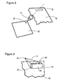
- the exploded view of Figure 3 shows a light emitting diode (LED) 22 that is electrically coupled to a circuit board 20.
- LED 22 is inserted into the apex 18 of the light guide 14 so that essentially all of the light emitted from the LED 22 is contained inside the light guide 14 and reflects off the internal surfaces thereof.
- the base 16 of the light guide 14 is aligned with the diffuser 12 so that the light can only escape through the diffuser 12.
- the diffuser 12 includes flanges 24 that project rearwardly from a diffusing surface 26 thereof.
- the flanges 24 typically project at a right angle from the diffusing surface 26, however, the flanges may be angled if necessary to achieve an optimum fit with the base 16 of the light guide 14.
- the flexible material of the light guide 14 is adhered to the flanges 24 in a manner that ensures that generally all of the light from the LED is directed to the diffuser 14.
- the flexible material may be adhered to the flanges 24 using glue or heat-sealed to the flanges 24.
- the light guide 14 may be held against the flanges 24 by an elastic band. It will be appreciated by a person skilled in the art that the light guide 14 may be coupled to the diffuser 12 in any manner that forms a suitable seal between the light guide 14 and the diffuser 12.
- the apex 18 of the light guide 14 is sized to surround the LED 22.
- the apex 18 of the light guide 14 is coupled to the board 20, using glue, for example.
- the light guide 14 may be clamped to the board 20 by another part of the telephone set 10.
- the LED 22 is not located on the board, but attached thereto by wires. If the LED 22 is a torpedo-type, the LED 22 must be clamped or clipped to a suitable component inside the telephone set 10. The light guide 14 can then be directly clamped, clipped, glued or heat sealed to the LED 22. If the LED 22 is a lighter weight type, the LED 22 may be directly sealed inside the light guide 14 by gluing or heat sealing the apex 18 of the light guide 14 shut so that it forms a bag around the LED 22, thus trapping the wires leading to the LED 22.
- An LED 22 assembly of this type is very light weight so there is no need to mount it to the telephone set 10, the rigidity of the wires and the bonding of the diffuser 12 is adequate to retain the LED 22.
- a glue patch may be added to the outer surface of the light guide 14 so that the light guide 14 may be bonded to the inside the housing of the telephone set 10.
- the outer surface of the light guide 14 may be provided with a flange or projection that can be coupled to the housing by gluing or heat sealing.
- the light emitted from message waiting light 12 appears to be evenly distributed because the light that a user sees is a reflection off the surface of the light guide 14. The user does not see any hot spots.
- the diffuser 12 of figures 1, 3 and 4 is shown as rectangular in shape. A person skilled in the art will appreciate that the diffuser may be curved rectangular, elliptical or any other suitable shape.
- the diffusing surface 26 is shown as being generally flush with the front face 13 of the telephone set 10, however, the diffusing surface 26 may project outwardly from the front face 13, if desired.
- the light guide 14 is shown as being generally conical, however, the light guide 14 is not limited to this shape. Since it is reflected light that is emitted through the diffuser, alternate shapes are also effective. Because the light guide is flexible, it can be formed into different shapes in order to accommodate a wide range of telephone sets 10 having many different internal structures.
Landscapes
- Physics & Mathematics (AREA)
- General Physics & Mathematics (AREA)
- Optics & Photonics (AREA)
- Engineering & Computer Science (AREA)
- Signal Processing (AREA)
- Telephone Set Structure (AREA)
Abstract
Description
Claims (9)
- An indicator light for a device, comprising a light emitting diode disposed within a housing of said device, a diffuser located on an outer face of the housing, and a light guide coupled to the housing for directing light from the light emitting diode to the diffuser, wherein said light guide is comprised of a flexible reflective material.
- An indicator light as claimed in claim 1 wherein said light guide is conical shaped having an apex and a base.
- An indicator light as claimed in claim 2 wherein said light emitting diode is inserted into said apex of the light guide and said diffuser is located at said base of said light guide.
- For use with an indicator light having a light emitting diode disposed within a housing of a device, the improvement comprising a light guide fabricated from a flat piece of flexible reflective material molded to provide a conical shape, said flat piece of flexible reflective material being coupled inside said housing between said light emitting diode and a diffuser.
- An indicator light for a device, comprising:a light emitting diode disposed within a housing of said device;a diffuser located on an outer face of the housing;a light guide extending between the diffuser and the light emitting diode for directing light from the light emitting diode to the diffuser, said light guide having a first end and a second end, said first end being coupled to the diffuser; andwherein said light guide is comprised of a flexible reflective material.
- An indicator light as claimed in claim 5, wherein said light guide has a base located at said first end and an apex located at said second end, said base being larger that said apex.
- An indicator light as claimed in claim 6, wherein said apex of said light guide surrounds the light emitting diode.
- An indicator light as claimed in claim 7 wherein said light guide is conical shaped, tapering from said base to said apex.
- An indicator light in accordance with any one of the foregoing claims wherein said device is a telephone.
Applications Claiming Priority (2)
| Application Number | Priority Date | Filing Date | Title |
|---|---|---|---|
| GBGB0202314.1A GB0202314D0 (en) | 2002-02-01 | 2002-02-01 | Indicator light for a telephone set |
| GB0202314 | 2002-02-01 |
Publications (2)
| Publication Number | Publication Date |
|---|---|
| EP1333226A2 true EP1333226A2 (en) | 2003-08-06 |
| EP1333226A3 EP1333226A3 (en) | 2007-09-12 |
Family
ID=9930182
Family Applications (1)
| Application Number | Title | Priority Date | Filing Date |
|---|---|---|---|
| EP03250642A Withdrawn EP1333226A3 (en) | 2002-02-01 | 2003-01-31 | Indicator light for telephone set |
Country Status (4)
| Country | Link |
|---|---|
| US (1) | US20030179565A1 (en) |
| EP (1) | EP1333226A3 (en) |
| CA (1) | CA2418251A1 (en) |
| GB (1) | GB0202314D0 (en) |
Cited By (3)
| Publication number | Priority date | Publication date | Assignee | Title |
|---|---|---|---|---|
| WO2006003510A1 (en) | 2004-06-30 | 2006-01-12 | Nokia Corporation | Multi colours device illumination |
| GB2449632A (en) * | 2007-05-23 | 2008-12-03 | O2 | A mobile telecommunications device, and an accessory for a mobile telecommunications device |
| EP2548758A3 (en) * | 2011-07-19 | 2017-12-20 | Siemens Industry, Inc. | Status indicating electric vehicle charging station |
Families Citing this family (3)
| Publication number | Priority date | Publication date | Assignee | Title |
|---|---|---|---|---|
| US9208783B2 (en) * | 2007-02-27 | 2015-12-08 | Nuance Communications, Inc. | Altering behavior of a multimodal application based on location |
| USD717762S1 (en) * | 2013-07-19 | 2014-11-18 | Samsung Electronics Co., Ltd. | Telephone set |
| EP3865764B1 (en) * | 2018-07-30 | 2025-09-03 | Thorn Lighting Ltd. | Luminaire |
Family Cites Families (11)
| Publication number | Priority date | Publication date | Assignee | Title |
|---|---|---|---|---|
| US3867019A (en) * | 1973-06-22 | 1975-02-18 | J R Eyerman | Photographic reflector |
| US4329017A (en) * | 1979-08-14 | 1982-05-11 | Kaptron, Inc. | Fiber optics communications modules |
| DE3419320C2 (en) * | 1984-05-24 | 1986-09-11 | Rheometron AG, Basel | Optoelectrical distance measuring device with an optical measuring probe |
| CA2134902C (en) * | 1994-04-07 | 2000-05-16 | Friedrich Bertignoll | Light diffusing apparatus |
| US5613761A (en) * | 1994-09-21 | 1997-03-25 | Raby, Sr.; Frederick R. | Material and method for fabricating a light fixture reflector, and, reflector produced thereby |
| US6176598B1 (en) * | 1999-04-16 | 2001-01-23 | Lowel-Light Manufacturing, Inc. | Light fixture flexible reflector |
| US6382817B1 (en) * | 1999-10-21 | 2002-05-07 | General Innovation, Llc | Convertible lighting fixture with adjustable reflectors and a method of installing a reflector to a lighting fixture |
| US6511204B2 (en) * | 1999-12-16 | 2003-01-28 | 3M Innovative Properties Company | Light tube |
| US6473552B1 (en) * | 2000-05-01 | 2002-10-29 | 3Com Corporation | Apparatus and method for signaling using a light pipe stylus |
| US6686847B1 (en) * | 2000-05-12 | 2004-02-03 | Hewlett-Packard Development Company, L.P. | Indicator with daylight visibility using a single light emitting diode |
| US6663261B1 (en) * | 2002-03-20 | 2003-12-16 | Thin-Lite Corporation | Moisture resistant flourescent light fixture |
-
2002
- 2002-02-01 GB GBGB0202314.1A patent/GB0202314D0/en not_active Ceased
-
2003
- 2003-01-31 EP EP03250642A patent/EP1333226A3/en not_active Withdrawn
- 2003-01-31 US US10/355,181 patent/US20030179565A1/en not_active Abandoned
- 2003-01-31 CA CA002418251A patent/CA2418251A1/en not_active Abandoned
Cited By (6)
| Publication number | Priority date | Publication date | Assignee | Title |
|---|---|---|---|---|
| WO2006003510A1 (en) | 2004-06-30 | 2006-01-12 | Nokia Corporation | Multi colours device illumination |
| EP1769622A1 (en) * | 2004-06-30 | 2007-04-04 | Nokia Corporation | Multi colours device illumination |
| US8167458B2 (en) | 2004-06-30 | 2012-05-01 | Core Wireless Licensing S.A.R.L. | Multi colours device illumination |
| US8608345B2 (en) | 2004-06-30 | 2013-12-17 | Core Wireless Licensing, S.a.r.l. | Multi colours device illumination |
| GB2449632A (en) * | 2007-05-23 | 2008-12-03 | O2 | A mobile telecommunications device, and an accessory for a mobile telecommunications device |
| EP2548758A3 (en) * | 2011-07-19 | 2017-12-20 | Siemens Industry, Inc. | Status indicating electric vehicle charging station |
Also Published As
| Publication number | Publication date |
|---|---|
| GB0202314D0 (en) | 2002-03-20 |
| EP1333226A3 (en) | 2007-09-12 |
| CA2418251A1 (en) | 2003-08-01 |
| US20030179565A1 (en) | 2003-09-25 |
Similar Documents
| Publication | Publication Date | Title |
|---|---|---|
| CN1954173B (en) | Lighting device for producing a substantially uniform illuminated appearance | |
| JPH07235207A (en) | Backlight | |
| US6685342B2 (en) | Prism structure for flash illumination devices | |
| TW200304531A (en) | Panel light source device and display device | |
| JP3699414B2 (en) | Backlight module connection structure | |
| JP2006032020A (en) | Liquid crystal display | |
| TW200424667A (en) | Liquid crystal display device with reinforced side | |
| CN114217472B (en) | Backlight module and display device | |
| CN100580518C (en) | Liquid crystal display device and dustproof method for liquid crystal display device | |
| US20030179565A1 (en) | Indicator light for a telephone set | |
| US8092052B2 (en) | Light emitting diode package for projection system | |
| US6966686B2 (en) | Surface light source device | |
| JP3624577B2 (en) | Backlight device | |
| JP3073340B2 (en) | Light guide plate device | |
| US7198379B2 (en) | Lens for electronic device and disk device having same | |
| JPH10319860A (en) | Liquid crystal display | |
| JPH09252337A (en) | Light guide | |
| CN209979975U (en) | Lateral-entering backlight module with light and thin structure | |
| JP5110582B2 (en) | Mobile device | |
| CN219225269U (en) | Side-in type backlight module capable of optimizing visual effect in front of lamp | |
| CN211554572U (en) | Backlight module with circular structure | |
| JP3798963B2 (en) | Information terminal | |
| JP2594609B2 (en) | Backlighting structure of display panel | |
| JPH07218913A (en) | Liquid crystal display device with backlight | |
| CN210072265U (en) | Side-in type backlight module |
Legal Events
| Date | Code | Title | Description |
|---|---|---|---|
| PUAI | Public reference made under article 153(3) epc to a published international application that has entered the european phase |
Free format text: ORIGINAL CODE: 0009012 |
|
| AK | Designated contracting states |
Designated state(s): AT BE BG CH CY CZ DE DK EE ES FI FR GB GR HU IE IT LI LU MC NL PT SE SI SK TR |
|
| AX | Request for extension of the european patent |
Extension state: AL LT LV MK RO |
|
| PUAL | Search report despatched |
Free format text: ORIGINAL CODE: 0009013 |
|
| AK | Designated contracting states |
Kind code of ref document: A3 Designated state(s): AT BE BG CH CY CZ DE DK EE ES FI FR GB GR HU IE IT LI LU MC NL PT SE SI SK TR |
|
| AX | Request for extension of the european patent |
Extension state: AL LT LV MK RO |
|
| RAP1 | Party data changed (applicant data changed or rights of an application transferred) |
Owner name: MITEL NETWORKS CORPORATION |
|
| AKX | Designation fees paid | ||
| REG | Reference to a national code |
Ref country code: DE Ref legal event code: 8566 |
|
| STAA | Information on the status of an ep patent application or granted ep patent |
Free format text: STATUS: THE APPLICATION IS DEEMED TO BE WITHDRAWN |
|
| 18D | Application deemed to be withdrawn |
Effective date: 20080313 |