EP1333128A1 - An insulating panel, a transport unit comprising such panels and a method of manufacture of suchs panels - Google Patents
An insulating panel, a transport unit comprising such panels and a method of manufacture of suchs panels Download PDFInfo
- Publication number
- EP1333128A1 EP1333128A1 EP02075500A EP02075500A EP1333128A1 EP 1333128 A1 EP1333128 A1 EP 1333128A1 EP 02075500 A EP02075500 A EP 02075500A EP 02075500 A EP02075500 A EP 02075500A EP 1333128 A1 EP1333128 A1 EP 1333128A1
- Authority
- EP
- European Patent Office
- Prior art keywords
- panel
- panels
- transport unit
- insulating
- cuts
- Prior art date
- Legal status (The legal status is an assumption and is not a legal conclusion. Google has not performed a legal analysis and makes no representation as to the accuracy of the status listed.)
- Withdrawn
Links
- 238000000034 method Methods 0.000 title claims description 14
- 238000004519 manufacturing process Methods 0.000 title claims description 8
- 230000036961 partial effect Effects 0.000 claims abstract description 22
- 239000011888 foil Substances 0.000 claims abstract description 14
- 239000011810 insulating material Substances 0.000 claims abstract description 8
- 230000000717 retained effect Effects 0.000 claims abstract description 5
- 239000002657 fibrous material Substances 0.000 claims description 33
- 238000005520 cutting process Methods 0.000 claims description 22
- 238000009413 insulation Methods 0.000 claims description 11
- 230000014759 maintenance of location Effects 0.000 claims description 7
- 230000001681 protective effect Effects 0.000 claims description 5
- 230000003313 weakening effect Effects 0.000 claims description 5
- 239000000853 adhesive Substances 0.000 claims description 2
- 230000001070 adhesive effect Effects 0.000 claims description 2
- 239000012774 insulation material Substances 0.000 abstract description 3
- 101100008050 Caenorhabditis elegans cut-6 gene Proteins 0.000 description 7
- 230000009471 action Effects 0.000 description 5
- 238000005452 bending Methods 0.000 description 5
- 239000000463 material Substances 0.000 description 5
- 238000009435 building construction Methods 0.000 description 4
- 210000002105 tongue Anatomy 0.000 description 3
- XLYOFNOQVPJJNP-UHFFFAOYSA-N water Substances O XLYOFNOQVPJJNP-UHFFFAOYSA-N 0.000 description 3
- 239000005022 packaging material Substances 0.000 description 2
- 238000011144 upstream manufacturing Methods 0.000 description 2
- 239000011230 binding agent Substances 0.000 description 1
- 230000033228 biological regulation Effects 0.000 description 1
- 238000010276 construction Methods 0.000 description 1
- 238000005553 drilling Methods 0.000 description 1
- 239000003292 glue Substances 0.000 description 1
- 238000005304 joining Methods 0.000 description 1
- 238000005259 measurement Methods 0.000 description 1
- 238000003801 milling Methods 0.000 description 1
- 238000004806 packaging method and process Methods 0.000 description 1
- 230000000149 penetrating effect Effects 0.000 description 1
- 230000035515 penetration Effects 0.000 description 1
- 230000008569 process Effects 0.000 description 1
- 230000009467 reduction Effects 0.000 description 1
- 230000002829 reductive effect Effects 0.000 description 1
- 230000006641 stabilisation Effects 0.000 description 1
- 230000003019 stabilising effect Effects 0.000 description 1
- 238000003860 storage Methods 0.000 description 1
- 239000013589 supplement Substances 0.000 description 1
- 239000002699 waste material Substances 0.000 description 1
Images



Classifications
-
- B—PERFORMING OPERATIONS; TRANSPORTING
- B65—CONVEYING; PACKING; STORING; HANDLING THIN OR FILAMENTARY MATERIAL
- B65D—CONTAINERS FOR STORAGE OR TRANSPORT OF ARTICLES OR MATERIALS, e.g. BAGS, BARRELS, BOTTLES, BOXES, CANS, CARTONS, CRATES, DRUMS, JARS, TANKS, HOPPERS, FORWARDING CONTAINERS; ACCESSORIES, CLOSURES, OR FITTINGS THEREFOR; PACKAGING ELEMENTS; PACKAGES
- B65D71/00—Bundles of articles held together by packaging elements for convenience of storage or transport, e.g. portable segregating carrier for plural receptacles such as beer cans or pop bottles; Bales of material
- B65D71/0088—Palletisable loads, i.e. loads intended to be transported by means of a fork-lift truck
- B65D71/0092—Palletisable loads, i.e. loads intended to be transported by means of a fork-lift truck provided with one or more rigid supports, at least one dimension of the supports corresponding to a dimension of the load, e.g. skids
-
- E—FIXED CONSTRUCTIONS
- E04—BUILDING
- E04B—GENERAL BUILDING CONSTRUCTIONS; WALLS, e.g. PARTITIONS; ROOFS; FLOORS; CEILINGS; INSULATION OR OTHER PROTECTION OF BUILDINGS
- E04B1/00—Constructions in general; Structures which are not restricted either to walls, e.g. partitions, or floors or ceilings or roofs
- E04B1/62—Insulation or other protection; Elements or use of specified material therefor
- E04B1/74—Heat, sound or noise insulation, absorption, or reflection; Other building methods affording favourable thermal or acoustical conditions, e.g. accumulating of heat within walls
- E04B1/76—Heat, sound or noise insulation, absorption, or reflection; Other building methods affording favourable thermal or acoustical conditions, e.g. accumulating of heat within walls specifically with respect to heat only
- E04B1/78—Heat insulating elements
- E04B1/80—Heat insulating elements slab-shaped
-
- B—PERFORMING OPERATIONS; TRANSPORTING
- B65—CONVEYING; PACKING; STORING; HANDLING THIN OR FILAMENTARY MATERIAL
- B65D—CONTAINERS FOR STORAGE OR TRANSPORT OF ARTICLES OR MATERIALS, e.g. BAGS, BARRELS, BOTTLES, BOXES, CANS, CARTONS, CRATES, DRUMS, JARS, TANKS, HOPPERS, FORWARDING CONTAINERS; ACCESSORIES, CLOSURES, OR FITTINGS THEREFOR; PACKAGING ELEMENTS; PACKAGES
- B65D2571/00—Bundles of articles held together by packaging elements for convenience of storage or transport, e.g. portable segregating carrier for plural receptacles such as beer cans, pop bottles; Bales of material
- B65D2571/00006—Palletisable loads, i.e. loads intended to be transported by means of a fork-lift truck
- B65D2571/00012—Bundles surrounded by a film
-
- B—PERFORMING OPERATIONS; TRANSPORTING
- B65—CONVEYING; PACKING; STORING; HANDLING THIN OR FILAMENTARY MATERIAL
- B65D—CONTAINERS FOR STORAGE OR TRANSPORT OF ARTICLES OR MATERIALS, e.g. BAGS, BARRELS, BOTTLES, BOXES, CANS, CARTONS, CRATES, DRUMS, JARS, TANKS, HOPPERS, FORWARDING CONTAINERS; ACCESSORIES, CLOSURES, OR FITTINGS THEREFOR; PACKAGING ELEMENTS; PACKAGES
- B65D2571/00—Bundles of articles held together by packaging elements for convenience of storage or transport, e.g. portable segregating carrier for plural receptacles such as beer cans, pop bottles; Bales of material
- B65D2571/00006—Palletisable loads, i.e. loads intended to be transported by means of a fork-lift truck
- B65D2571/0008—Load supporting elements
- B65D2571/00092—Load supporting elements formed by specially placed articles or parts thereof
-
- B—PERFORMING OPERATIONS; TRANSPORTING
- B65—CONVEYING; PACKING; STORING; HANDLING THIN OR FILAMENTARY MATERIAL
- B65D—CONTAINERS FOR STORAGE OR TRANSPORT OF ARTICLES OR MATERIALS, e.g. BAGS, BARRELS, BOTTLES, BOXES, CANS, CARTONS, CRATES, DRUMS, JARS, TANKS, HOPPERS, FORWARDING CONTAINERS; ACCESSORIES, CLOSURES, OR FITTINGS THEREFOR; PACKAGING ELEMENTS; PACKAGES
- B65D85/00—Containers, packaging elements or packages, specially adapted for particular articles or materials
- B65D85/30—Containers, packaging elements or packages, specially adapted for particular articles or materials for articles particularly sensitive to damage by shock or pressure
- B65D85/46—Containers, packaging elements or packages, specially adapted for particular articles or materials for articles particularly sensitive to damage by shock or pressure for bricks, tiles or building blocks
-
- E—FIXED CONSTRUCTIONS
- E04—BUILDING
- E04B—GENERAL BUILDING CONSTRUCTIONS; WALLS, e.g. PARTITIONS; ROOFS; FLOORS; CEILINGS; INSULATION OR OTHER PROTECTION OF BUILDINGS
- E04B1/00—Constructions in general; Structures which are not restricted either to walls, e.g. partitions, or floors or ceilings or roofs
- E04B1/62—Insulation or other protection; Elements or use of specified material therefor
- E04B1/74—Heat, sound or noise insulation, absorption, or reflection; Other building methods affording favourable thermal or acoustical conditions, e.g. accumulating of heat within walls
- E04B2001/741—Insulation elements with markings, e.g. identification or cutting template
Definitions
- the present invention relates to an insulating panel according to the preamble of claim 1, a transport unit comprising a plurality of insulating panels and a method of manufacture of said panels.
- the fibrous materials are frequently supplied to the users in the form of panels in relatively large dimensions.
- the insulating panels are supplied in standard dimensions, typically 2000 mm in length and 600 mm in width, or multiples of these measurements, e.g. 2000 mm x 1200 mm or 1000 mm x 600 mm.
- the insulating panels are stacked on a palette in transport units and transported from the manufacturer to the building site. The dimensions are determined by industry standards as well as constrictions by the transport storage facilities.
- the insulation material manufacturer and the users want a reduction in the packaging materials, since these packaging materials cannot be used at the building site and therefore need to be disposed of.
- a transport unit is known where insulating panels are stacked in a stack on two support elements made of an insulating material. A foil is wrapped around the stack of panels and each of the support elements.
- This transport unit is only suitable for supporting one single stack in each transport unit.
- the dimensions of each panel may be relatively large (2000x1200 mm) and thus may result in extensive handling and fitting by the end user at the building site.
- a transport unit where a plurality of insulating panels are stacked in two or more stacks adjacent each other on mutually spaced support elements of a material suitable for use for insulation purposes.
- the support elements may have different orientations relative to the position of the stacks.
- the stacks of panels and the support elements are enclosed in a protective foil wrapping.
- This wrapping also provides for a stable transport unit.
- Several insulating panels can only be stacked in a specific way and up to a predetermined height.
- this transport unit is composed of insulating panels of small format, e.g. 1000x600 mm, length and width respectively, and it is lifted by normal lifting means, such as a lift fork, there is a risk that the whole transport unit may bend or even collapse as the stacks of panels collapse or the panels in each of the stacks slide away from each other. Rather, in order to ensure a stable transport unit, the dimensions of the panels are typically 2000x600 mm in the two stacks. At the user's end, the panels may be cut into size before it is fitted into the building construction, e.g. a roof construction.
- an object of the present invention to provide an insulating panel that allows for a transport unit with a good stability. It is another object to provide a insulating panel and a transport unit, which results in greater flexibility in the handling of the insulating panels at the user's end, whilst maintaining the advantages relating to the transport. In addition, it is the object to provide a transport unit without the above-identified drawbacks concerning the water penetration. Moreover, it is an object to keep the costs of producing the insulating panels according to the invention low.
- the invention relates to an insulating panel of fibrous material for insulation purposes, said panel being stackable on support means with one or more similarly dimensioned panels provided in predetermined sizes for transport and handling, said panel comprising a top and bottom surface, wherein the panel is provided with at least one line of partial slitting in at least the top surface leaving a section of fibrous material with a thickness which is less than the thickness of the panel.
- the insulating panel may be produced in large dimensions and transported in a stack in a stable transport unit since the slit helps the two portions of a panel to prevent the panel from bending down in the middle when the transport unit or the panel alone is lifted up.
- the section layer of fibrous material ensures the stability of the stack as this section functions as a bridge between what would otherwise be two stacks of panels.
- An insulating panel according to the invention is suitable for transport on support units of fibrous material, thus reducing the amount of waste material considerably.
- This "bridging" section is preferably substantially thin - e.g. 3-50 %, most preferably approx. 5-30% of the panel thickness - so that the person fitting the panels into the building construction can easily break the panel into the predetermined smaller sizes defined in the panel by the position of the slitting without the need of tools.
- the at least one line of partial slitting is preferably a traverse line of slitting in the panel, so that e.g. a panel of 2000x600 mm may be divided into two 1000x600 mm.
- the panels may even be bigger, e.g. 4000x2400 mm or other dimensions. Other suitable divisions of cause may also be provided.
- the standard-sized insulation panels for the transport unit may be provided with customer-specified subdivisions.
- the slitting consists of first and second pre-cuts from each side with a distance between the first and second pre-cuts.
- the slits are provided such that there is a distance between the bottoms of the two pre-cuts.
- the pre-cuts provide stability from both bending tendencies in both the upward and the downward direction when the transport unit is lifted or the panel is lifted off the stack in the transport unit.
- the thickness of the bridging section of fibrous material may be reduced, leaving the resulting edge relatively smooth.
- the first and second pre-cuts are substantially perpendicular to the top surface of the panel.
- the resulting edges of the divided panels have a shape, which is easy to fit to a neighbouring panel when fitting the insulation into the building construction.
- the first and second slits are substantially of the same depth.
- the panels have the same stability independent of their orientation.
- the first and second pre-cuts may be in the same plane.
- the resulting edges of the divided panels are relatively smooth and planar corresponding to the normal side edges of the panel.
- the second pre-cut is provided in a plane displaced from the first pre-cut.
- the resulting edges are automatically provided with an overlap for an overlap fitting in the building construction, i.e. a tongue and groove type of fitting.
- ⁇ -supplement extra thickness in the insulation
- the sum of the depth lengths of the first and second pre-cuts is substantially equal to the thickness of the panel.
- first and second pre-cuts are provided with an inclined angle relative to the top surface.
- an alternative geometry of the resulting edges of the divided panel may be provided, e.g. one or more inclined edge surfaces on the resulting edge.
- a weakening line is provided in the panel constituting the slitting line.
- the insulating panel may be provided with a weak breaking line during the production of the fibrous material, e.g. by providing a line substantially free of fibres but mainly comprising binding material in the fibrous web.
- two or more slitting lines may be provided in the panel.
- several sub-divisions may be provided in the panels, e.g. customer-specific sub-divisions.
- the slitting line provided preferably divides the panel in two equal halves.
- the panel may be divided into two panels in corresponding standard size.
- the insulating panel may involve at least one longitudinal slitting line apart from traverse slitting lines.
- the invention also relates to a transport unit comprising a plurality of panels of insulating material said panels being stacked on support means, wherein the transport unit comprises at least one stack of a number of stacked panels, where at least one is provided with one or more partial slits, said panels being retained together and protected by wrapping foil.
- a stable transport unit of insulating panels is provided, which reduces or even removes the initially mentioned drawbacks with the known transport units with respect to handling and transport.
- the transport unit according to the invention may in particular include that the panels are stacked in one or more stacks on support means consisting of mutually spaced support elements consisting of fibrous material suitable to be used for insulation purposes.
- support means consisting of mutually spaced support elements consisting of fibrous material suitable to be used for insulation purposes.
- the invention furthermore relates to a method of manufacture of an insulating panel with at least one partial slitting, said method involving the step of providing at least one weakening line by means for longitudinal cutting in an advancing web of insulating material, where the width of the web constitutes the panel length, and intermittently cutting the advancing web into insulating panels with a predetermined panel width by a second traverse cutting means downstream the longitudinal cutting means after having cured the advancing web of insulating material.
- one or more partial pre-cuts in the resulting insulating panels may be provided in a simple manner without adding significantly to the production costs as the method of producing the partial slitting may be implemented without major problems in an existing production line.
- the longitudinal cutting is provided either before or after the curing of the advancing web.
- the longitudinal cutting preferably includes a first and second cutting means providing slits on each side of the web.
- a transport unit 2 is shown where two stacks 1a and 1b of insulating panels 1 of insulating fibrous material are stacked on two support elements 3 and provided with retention means, such as a wrapping foil 4.
- the insulating panels 1 have a traverse, partial slitting 5 dividing the individual panels 1 into sections 1', 1".
- the insulating panel 1 is made of an insulation material with a density of more than approx. 20-30 kg/m 3 and preferably in the order of 60-80 kg/m 3 .
- the slitting 5 comprises one or two pre-cuts 6, 8 leaving a section 7 of fibrous material connecting or "bridging" the sections 1', 1" of the panel 1.
- the remaining section 7 has a thickness d, which is substantially smaller than the overall thickness D of the panel 1 (see fig. 8). This remaining section 7 is easily breakable by a person without the need of tools but sufficiently strong to hold the panels together during transport and handling of the insulating panel during both loading and unloading to and from the transport unit.
- the panel 1 is provided with a pre-cut 6 extending from the top surface of the panel 1 into the fibrous panel 1 dividing the panel 1 into a first panel section 1' and a second panel section 1" leaving a layer of fibrous material in the lower section 7 of the panel 1.
- the panel 1 is provided with a first pre-cut 6 and a second pre-cut 8 extending perpendicularly from the top surface and the bottom surface of the panel 1, respectively.
- the pre-cuts 6, 8 are cut in the same (perpendicular) plane extending into the fibrous panel 1 dividing the panel 1 into a first panel section 1' and a second panel section 1" leaving a layer of fibrous material in the central section 7 of the panel 1.
- the panel 1 is provided with a first pre-cut 6 and a second pre-cut 8 extending perpendicularly from the top surface and the bottom surface of the panel 1, respectively.
- the pre-cuts 6, 8 are cut in parallel planes displaced from one another.
- the pre-cuts extend into the fibrous panel 1 dividing the panel 1 into a first panel section 1' and a second panel section 1" leaving a layer of fibrous material in the central section 7 of the panel 1.
- the pre-cuts 6, 8 are off-set and extend less than half way through the panel 1 leaving an expected breakage line in the remaining section of fibrous material, which is inclined.
- the panel 1 is provided with a first pre-cut 6 and a second pre-cut 8 extending perpendicularly from the top surface and the bottom surface of the panel 1, respectively.
- the pre-cuts 6, 8 are cut in parallel planes displaced from one another, both planes being parallel with the top and bottom surfaces.
- the pre-cuts extend into the fibrous panel 1 dividing the panel 1 into a first panel section 1' and a second panel section 1" leaving a layer of fibrous material in the central section 7 of the panel 1.
- the pre-cuts 6, 8 extend substantially half way through the panel 1 leaving an expected breakage line in the remaining section of fibrous material, which is essentially parallel with the top and bottom surfaces of the panel 1.
- the panel 1 is provided with a first pre-cut 6 and a second pre-cut 8 extending from the top surface and the bottom surface of the panel 1, respectively, and cut in planes inclined relative to the top surface and displaced from one another.
- the pre-cuts 6, 8 could be in the same inclined plane.
- the pre-cuts extend into the fibrous panel 1 dividing the panel 1 into a first panel section 1' and a second panel section 1" leaving a layer of fibrous material in the central section 7 of the panel 1.
- an insulating panel 1 may be provided with a plurality of traverse, partial slits 5, e.g. two as shown in the figure dividing the panel 1 into three sub-sections 1', 1'', 1'''.
- the panel 1 has a panel thickness D and the pre-cuts 6, 8 extend into the panel 1 with a distance d 1 , d 2 respectively.
- the distances d 1 , d 2 may be either substantially equal or different, preferably d 1 ⁇ d 2 .
- the distance d may be 10-15 mm.
- the distance i.e. the thickness d of the connecting or "bridging" section of fibrous material, may be between 3-50 %, most preferably 5-30 %, of the insulating panel thickness D, which typically may be 30-200 mm or even up to 300 mm.
- FIG 9 is shown a detailed view of two panel sections 1' and 1" of a panel 1 according to the embodiment shown in fig. 5 after the panel 1 has been divided.
- the panel 1 is broken along the partial slit consisting of two pre-cuts 6, 8.
- the pre-cuts 6, 8 define a first and second edge surface 61, 62 and 81, 82 of the first and second panel sections 1', 1", respectively.
- the breaking action results in a breaking surface 71 and 72 of the two panel sections, as the connecting section 7 of fibrous material is broken apart.
- breaking surfaces 71, 72 are essentially parallel with the top and bottom surfaces of the panel 1, since the pre-cuts are perpendicular to the top surface and the sum of the depths of the first and second pre-cuts equals the thickness of the panel 1. Due to the off-set of the first and second pre-cuts 6, 8, the resulting joining edge of the panel sections 1'; 1" are provided with geometrically corresponding, overlapping tongues. When the panel sections 1', 1" are rejoined, these tongues ensure that no gap appears in the insulation.
- FIG 10 is shown a detailed view of two panel sections 1' and 1" of a panel 1 according to the embodiment shown in fig. 3 after the panel 1 has been divided.
- the panel 1 is broken along the partial slit consisting of two pre-cuts 6, 8.
- the pre-cuts 6, 8 define a first and second edge surface 61, 62 and 81, 82 of the first and second panel sections 1', 1", respectively.
- the breaking action results in a breaking surface 71 and 72 of the two panel sections, as the connecting section 7 of fibrous material is broken apart.
- These breaking surfaces 71, 72 are essentially parallel and in the same plane as the other edge surfaces 61, 81 and 62, 82 of each of the sections 1', 1".
- the panel sections 1'; 1" are subsequently rejoined.
- a small gap g may appear between the two panel sections 1', 1". However, if the distance d , i.e. the length of the breaking surfaces 71, 72, is relatively small, the breakage results in relative even breaking surfaces, and the size of the gap g is consequently minimised.
- the application of lifting forces F 1 when handling the panel causes a bending action f 1 in the bridging section 7 between the panel sections 1' and 1".
- the two surfaces 61 and 62 of the upper pre-cut 6 will then be moved against each other. This results in a resistance against the bending and thus contributes to the stabilisation of the panel 1.
- a bending action f 2 may be applied if the panel is lifted up from a stack in a transport unit as forces F 2 are applied to the panel.
- the applied forces F 2 have an opposite direction than the first described example.
- the stabilising effect is then provided by the second, lower pre-cut 8 by its surfaces 81 and 82.
- a transport unit 2 may comprise more than one stack of insulating panels 1.
- the panels 1 on the transport unit 2 may be a mix of different types of insulating panels 1, i.e. insulating panels with one or more pre-cuts 5 mixed with insulating panels 1c without pre-cuts, or also panels having inclined pre-cuts, as shown in figure 6.
- FIG. 13 to 16 various embodiments of the method of producing the pre-cuts in the insulating panels are shown.
- an advancing web 10 of fibrous material is advanced through a curing oven 13 in which the fibrous material is cured. Downstream the curing 13, the web 10 of insulating fibrous material is cut into panels in a cutting station generally referred to by 14.
- the pre-cuts are made in the advancing web 10 by inserting blades 11, 12 from each side into the soft web 10 upstream the curing 13. These blades 11, 12 each leave a groove in the web 10. The web 10 is then cured and cut into panels and these grooves then constitute traverse pre-cuts in the resulting panels.
- the grooves may be provided by a cutting action downstream the curing 13.
- cutting means are positioned at each side of the web 10.
- the cutting means could be a first and second circular saw 15, 16 placed at each side of the web 10.
- the cutting means 15, 16 provide a longitudinal groove in each side of the web 10.
- the web 10 is cut into panels and the longitudinal groove in the web becomes a transverse partial pre-cut in the insulating panels.
- Other suitable cutting means could be drilling or milling the pre-cuts in the web.
- a single blade 17 is inserted extending through the entire "wet" web 10 upstream the curing 13, as shown in fig. 15 and 16.
- This blade 17 provides the web 10 with a longitudinal groove 18.
- the web 10 is bonded together along the groove 18 as the binder material binds the two sections 10', 10" of the web together.
- the fibres of the web material are removed by the blade 17.
- the web 10 is cut into panels at the cutting station 14.
- the resulting panel is shown in fig. 17.
- the panel 1 comprises two partial sections 1', 1", which are joined together by a slit or line of weakness 5', and wherein said slit is substantially free of fibres compared to the rest of the panel.
- the groove 18 provided by the blade 17 may extend throughout the entire thickness of the web 10, or may only extend partially into the thickness of the web.
- the insulating panel 1 may comprise both traverse and longitudinal partial slittings 5, dividing the panel 1 into e.g. four panel sections 1', 1", 1''', 1"".
- the preferred dimensions of such insulating panel sections could be 1000 x 600 mm and the overall dimensions of the insulating panel 1 remaining 2000 x 1200 mm, whereby the existing packaging and transport equipment may be used.
- FIG 19 an embodiment of a transport unit is shown, where the stack of insulating panels 1 is wrapped by a foil 4a and the support feet 3 are wrapped in separate foils 4b.
- the foil-wrapped feet 3 are joined to the foil 4a of the stack by adhesive means, such as glue.
- FIG 20 an embodiment is shown, where two or more adjacent stacks 1a, 1b of insulating panels 1 are positioned on a load carrying surface of a common base support pallet 30.
- This base support pallet 30 is made of one or more support panels 31 of a fibrous material suitable for insulation purposes. Underneath, support feet 32 made of a similar fibrous material are arranged for creating a clearance underneath the base support surface in order to allow for lifting equipment to handle the transport unit. Alternatively, the panels may be stacked on conventional pallets.
- the stack of panels 1 are positioned on feet supporting elements 3 of a fibrous material.
- a flexible top cover 4d is placed on top of the stack.
- This top cover 4d could be a sheet of foil material or the like.
- a foil 4c is wrapped around the stack of panels 1, the top cover 4d and the feet elements 3. In this manner, the panels 1 in the stack are retained and the stability of the transport unit is ensured in a simple way.
Landscapes
- Engineering & Computer Science (AREA)
- Physics & Mathematics (AREA)
- Architecture (AREA)
- Mechanical Engineering (AREA)
- Acoustics & Sound (AREA)
- Electromagnetism (AREA)
- Civil Engineering (AREA)
- Structural Engineering (AREA)
- Building Environments (AREA)
- Panels For Use In Building Construction (AREA)
- Refrigerator Housings (AREA)
- Laminated Bodies (AREA)
- Insulating Of Coils (AREA)
- Securing Of Glass Panes Or The Like (AREA)
- Pallets (AREA)
- Packaging Of Annular Or Rod-Shaped Articles, Wearing Apparel, Cassettes, Or The Like (AREA)
- Buffer Packaging (AREA)
Abstract
In order to improve the stability of a transport unit 2 comprising a plurality of panels
1 of insulating material, where said panels 1 are stacked on support means 3, wherein
the transport unit 2 comprises at least one stack of a number of stacked panels 1, at
least one panel 1 is provided with one or more partial slits 5, said panels 1 being
retained together and protected by wrapping foil 4. By providing an insulating panel
1 with pre-cuts 6, 8, a transport unit may be provided with a good stability which
improves both handling and transport of insulating panels between the producer of
fibrous insulation material and the end users at the building sites.
Description
- The present invention relates to an insulating panel according to the preamble of
claim 1, a transport unit comprising a plurality of insulating panels and a method of manufacture of said panels. - Traditionally, the fibrous materials are frequently supplied to the users in the form of panels in relatively large dimensions. Accordingly, the insulating panels are supplied in standard dimensions, typically 2000 mm in length and 600 mm in width, or multiples of these measurements, e.g. 2000 mm x 1200 mm or 1000 mm x 600 mm. The insulating panels are stacked on a palette in transport units and transported from the manufacturer to the building site. The dimensions are determined by industry standards as well as constrictions by the transport storage facilities.
- For economical and ecological reasons, the insulation material manufacturer and the users want a reduction in the packaging materials, since these packaging materials cannot be used at the building site and therefore need to be disposed of.
- From DE 42 18 354 A1, a transport unit is known where insulating panels are stacked in a stack on two support elements made of an insulating material. A foil is wrapped around the stack of panels and each of the support elements. This transport unit is only suitable for supporting one single stack in each transport unit. The dimensions of each panel may be relatively large (2000x1200 mm) and thus may result in extensive handling and fitting by the end user at the building site.
- From EP 0 946 394 B1, a transport unit is known, where a plurality of insulating panels are stacked in two or more stacks adjacent each other on mutually spaced support elements of a material suitable for use for insulation purposes. The support elements may have different orientations relative to the position of the stacks. The stacks of panels and the support elements are enclosed in a protective foil wrapping.
- This wrapping also provides for a stable transport unit. Several insulating panels can only be stacked in a specific way and up to a predetermined height. When this transport unit is composed of insulating panels of small format, e.g. 1000x600 mm, length and width respectively, and it is lifted by normal lifting means, such as a lift fork, there is a risk that the whole transport unit may bend or even collapse as the stacks of panels collapse or the panels in each of the stacks slide away from each other. Rather, in order to ensure a stable transport unit, the dimensions of the panels are typically 2000x600 mm in the two stacks. At the user's end, the panels may be cut into size before it is fitted into the building construction, e.g. a roof construction.
- With a protective wrapping foil of the entire transport unit, there may be a risk of water penetrating the foil and becoming trapped in the bottom of the unit, i.e. the support element. This is a particular problem, when support elements of fibrous material useable for insulation purposes are used. These support elements are useless if they are soaked in water.
- In view of the transport units known in the art, it is an object of the present invention to provide an insulating panel that allows for a transport unit with a good stability. It is another object to provide a insulating panel and a transport unit, which results in greater flexibility in the handling of the insulating panels at the user's end, whilst maintaining the advantages relating to the transport. In addition, it is the object to provide a transport unit without the above-identified drawbacks concerning the water penetration. Moreover, it is an object to keep the costs of producing the insulating panels according to the invention low.
- These objects are achieved by the invention.
- The invention relates to an insulating panel of fibrous material for insulation purposes, said panel being stackable on support means with one or more similarly dimensioned panels provided in predetermined sizes for transport and handling, said panel comprising a top and bottom surface, wherein the panel is provided with at least one line of partial slitting in at least the top surface leaving a section of fibrous material with a thickness which is less than the thickness of the panel.
- Due to the partial slitting or pre-cut, the insulating panel may be produced in large dimensions and transported in a stack in a stable transport unit since the slit helps the two portions of a panel to prevent the panel from bending down in the middle when the transport unit or the panel alone is lifted up. The section layer of fibrous material ensures the stability of the stack as this section functions as a bridge between what would otherwise be two stacks of panels. An insulating panel according to the invention is suitable for transport on support units of fibrous material, thus reducing the amount of waste material considerably.
- This "bridging" section is preferably substantially thin - e.g. 3-50 %, most preferably approx. 5-30% of the panel thickness - so that the person fitting the panels into the building construction can easily break the panel into the predetermined smaller sizes defined in the panel by the position of the slitting without the need of tools. The at least one line of partial slitting is preferably a traverse line of slitting in the panel, so that e.g. a panel of 2000x600 mm may be divided into two 1000x600 mm. The panels may even be bigger, e.g. 4000x2400 mm or other dimensions. Other suitable divisions of cause may also be provided. By the invention, it is also realised that the standard-sized insulation panels for the transport unit may be provided with customer-specified subdivisions.
- In the preferred embodiment of the invention, the slitting consists of first and second pre-cuts from each side with a distance between the first and second pre-cuts. The slits are provided such that there is a distance between the bottoms of the two pre-cuts. Hereby, the pre-cuts provide stability from both bending tendencies in both the upward and the downward direction when the transport unit is lifted or the panel is lifted off the stack in the transport unit. Moreover, the thickness of the bridging section of fibrous material may be reduced, leaving the resulting edge relatively smooth.
- In a first preferred embodiment of the invention, the first and second pre-cuts are substantially perpendicular to the top surface of the panel. Hereby, the resulting edges of the divided panels have a shape, which is easy to fit to a neighbouring panel when fitting the insulation into the building construction.
- In the preferred first embodiment of the invention, the first and second slits are substantially of the same depth. Hereby, the panels have the same stability independent of their orientation.
- In the preferred first embodiment, the first and second pre-cuts may be in the same plane. Hereby, the resulting edges of the divided panels are relatively smooth and planar corresponding to the normal side edges of the panel.
- In another preferred embodiment of the invention, the second pre-cut is provided in a plane displaced from the first pre-cut. Hereby, the resulting edges are automatically provided with an overlap for an overlap fitting in the building construction, i.e. a tongue and groove type of fitting. This is particularly advantageous since regulations prescribe the use of extra thickness in the insulation (the so-called λ-supplement) if the gap between two insulating panels is more than a certain amount, typically if more than 5 mm. In a particular advantageous embodiment of this insulating panel, the sum of the depth lengths of the first and second pre-cuts is substantially equal to the thickness of the panel. Hereby, the resulting breaking line when the panel is divided, is essentially parallel with the top and bottom surfaces making the fitting easier.
- In another embodiment, first and second pre-cuts are provided with an inclined angle relative to the top surface. Hereby, an alternative geometry of the resulting edges of the divided panel may be provided, e.g. one or more inclined edge surfaces on the resulting edge.
- In an alternative embodiment of the invention, a weakening line is provided in the panel constituting the slitting line. The insulating panel may be provided with a weak breaking line during the production of the fibrous material, e.g. by providing a line substantially free of fibres but mainly comprising binding material in the fibrous web.
- By the invention, it is realised that two or more slitting lines may be provided in the panel. Hereby, several sub-divisions may be provided in the panels, e.g. customer-specific sub-divisions. In particular, the slitting line provided preferably divides the panel in two equal halves. Hereby, the panel may be divided into two panels in corresponding standard size. Accordingly, the insulating panel may involve at least one longitudinal slitting line apart from traverse slitting lines.
- The invention also relates to a transport unit comprising a plurality of panels of insulating material said panels being stacked on support means, wherein the transport unit comprises at least one stack of a number of stacked panels, where at least one is provided with one or more partial slits, said panels being retained together and protected by wrapping foil. Hereby, a stable transport unit of insulating panels is provided, which reduces or even removes the initially mentioned drawbacks with the known transport units with respect to handling and transport.
- The transport unit according to the invention may in particular include that the panels are stacked in one or more stacks on support means consisting of mutually spaced support elements consisting of fibrous material suitable to be used for insulation purposes. Hereby, there is no need for a wooden palette or the like which the end user must be disposed of.
- The invention furthermore relates to a method of manufacture of an insulating panel with at least one partial slitting, said method involving the step of providing at least one weakening line by means for longitudinal cutting in an advancing web of insulating material, where the width of the web constitutes the panel length, and intermittently cutting the advancing web into insulating panels with a predetermined panel width by a second traverse cutting means downstream the longitudinal cutting means after having cured the advancing web of insulating material.
- Hereby, one or more partial pre-cuts in the resulting insulating panels may be provided in a simple manner without adding significantly to the production costs as the method of producing the partial slitting may be implemented without major problems in an existing production line.
- The longitudinal cutting is provided either before or after the curing of the advancing web. The longitudinal cutting preferably includes a first and second cutting means providing slits on each side of the web.
- In the following the invention is described in more detail with reference to the accompanying drawings, in which
- fig. 1 is a perspective view of a transport unit according to an embodiment of the invention,
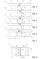
- figs. 2 to 7 are schematic cross-sectional views of an insulating panel according to various embodiments of the invention,
- fig. 8 is a detailed schematic cross-sectional view of the insulating panel of fig. 3,
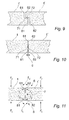
- figs. 9 and 10 are detailed schematic cross-sectional view of the panels of fig. 3 and fig. 5, respectively, reassembled after the breakage along the weakening line,
- fig. 11 is a schematic cross-sectional view of a panel prior to the breakage,
- fig. 12 is a perspective view of a transport unit according to a second embodiment of the invention,
- figs. 13 and 14 are principal side view of two embodiments of producing the partial pre-cuts,
- fig. 15 is a principal side view of an alternative method of producing the slitting in the insulating panels,
- fig. 16 is the same viewed from above,
- fig. 17 is a schematic, cross-sectional view of the insulating panel resulting from the method shown in figs. 15 and 16,
- fig. 18 is a schematic top view of an insulating panel according to a variant of the preferred embodiment of the invention and
- figs. 19 to 21 show various further embodiments of a transport unit according to the invention.
-
- In figure 1, a
transport unit 2 is shown where twostacks panels 1 of insulating fibrous material are stacked on twosupport elements 3 and provided with retention means, such as a wrappingfoil 4. The insulatingpanels 1 have a traverse,partial slitting 5 dividing theindividual panels 1 intosections 1', 1". The insulatingpanel 1 is made of an insulation material with a density of more than approx. 20-30 kg/m3 and preferably in the order of 60-80 kg/m3. - As shown in the figures 2 to 7, the slitting 5 comprises one or two
pre-cuts section 7 of fibrous material connecting or "bridging" thesections 1', 1" of thepanel 1. The remainingsection 7 has a thickness d, which is substantially smaller than the overall thickness D of the panel 1 (see fig. 8). This remainingsection 7 is easily breakable by a person without the need of tools but sufficiently strong to hold the panels together during transport and handling of the insulating panel during both loading and unloading to and from the transport unit. - In figure 2, the
panel 1 is provided with a pre-cut 6 extending from the top surface of thepanel 1 into thefibrous panel 1 dividing thepanel 1 into a first panel section 1' and asecond panel section 1" leaving a layer of fibrous material in thelower section 7 of thepanel 1. - In figure 3, the
panel 1 is provided with afirst pre-cut 6 and asecond pre-cut 8 extending perpendicularly from the top surface and the bottom surface of thepanel 1, respectively. Thepre-cuts fibrous panel 1 dividing thepanel 1 into a first panel section 1' and asecond panel section 1" leaving a layer of fibrous material in thecentral section 7 of thepanel 1. - In figure 4, the
panel 1 is provided with afirst pre-cut 6 and asecond pre-cut 8 extending perpendicularly from the top surface and the bottom surface of thepanel 1, respectively. Thepre-cuts fibrous panel 1 dividing thepanel 1 into a first panel section 1' and asecond panel section 1" leaving a layer of fibrous material in thecentral section 7 of thepanel 1. Thepre-cuts panel 1 leaving an expected breakage line in the remaining section of fibrous material, which is inclined. - In figure 5, the
panel 1 is provided with afirst pre-cut 6 and asecond pre-cut 8 extending perpendicularly from the top surface and the bottom surface of thepanel 1, respectively. Thepre-cuts fibrous panel 1 dividing thepanel 1 into a first panel section 1' and asecond panel section 1" leaving a layer of fibrous material in thecentral section 7 of thepanel 1. Thepre-cuts panel 1 leaving an expected breakage line in the remaining section of fibrous material, which is essentially parallel with the top and bottom surfaces of thepanel 1. - In figure 6, the
panel 1 is provided with afirst pre-cut 6 and asecond pre-cut 8 extending from the top surface and the bottom surface of thepanel 1, respectively, and cut in planes inclined relative to the top surface and displaced from one another. Alternatively, thepre-cuts fibrous panel 1 dividing thepanel 1 into a first panel section 1' and asecond panel section 1" leaving a layer of fibrous material in thecentral section 7 of thepanel 1. - As shown in figure 7, an insulating
panel 1 according to the invention may be provided with a plurality of traverse,partial slits 5, e.g. two as shown in the figure dividing thepanel 1 into three sub-sections 1', 1'', 1'''. - As shown in figure 8, the
panel 1 has a panel thickness D and thepre-cuts panel 1 with a distance d1, d2 respectively. The distances d1, d2 may be either substantially equal or different, preferably d1 ≥ d2. Irrespective of the direction and the depths of thepre-cuts second pre-cut - In figure 9 is shown a detailed view of two
panel sections 1' and 1" of apanel 1 according to the embodiment shown in fig. 5 after thepanel 1 has been divided. Thepanel 1 is broken along the partial slit consisting of twopre-cuts pre-cuts second edge surface second panel sections 1', 1", respectively. The breaking action results in a breakingsurface section 7 of fibrous material is broken apart. These breaking surfaces 71, 72 are essentially parallel with the top and bottom surfaces of thepanel 1, since the pre-cuts are perpendicular to the top surface and the sum of the depths of the first and second pre-cuts equals the thickness of thepanel 1. Due to the off-set of the first andsecond pre-cuts panel sections 1', 1" are rejoined, these tongues ensure that no gap appears in the insulation. - In figure 10 is shown a detailed view of two
panel sections 1' and 1" of apanel 1 according to the embodiment shown in fig. 3 after thepanel 1 has been divided. Thepanel 1 is broken along the partial slit consisting of twopre-cuts pre-cuts second edge surface second panel sections 1', 1", respectively. The breaking action results in a breakingsurface section 7 of fibrous material is broken apart. These breaking surfaces 71, 72 are essentially parallel and in the same plane as the other edge surfaces 61, 81 and 62, 82 of each of thesections 1', 1". The panel sections 1'; 1" are subsequently rejoined. A small gap g may appear between the twopanel sections 1', 1". However, if the distance d, i.e. the length of the breaking surfaces 71, 72, is relatively small, the breakage results in relative even breaking surfaces, and the size of the gap g is consequently minimised. - As shown in figure 11, the application of lifting forces F1 when handling the panel causes a bending action f1 in the
bridging section 7 between thepanel sections 1' and 1". However, as shown in the figure, the twosurfaces upper pre-cut 6 will then be moved against each other. This results in a resistance against the bending and thus contributes to the stabilisation of thepanel 1. Likewise, a bending action f2 may be applied if the panel is lifted up from a stack in a transport unit as forces F2 are applied to the panel. In this case, the applied forces F2 have an opposite direction than the first described example. The stabilising effect is then provided by the second,lower pre-cut 8 by itssurfaces - As shown in figure 12, a
transport unit 2 according to the invention may comprise more than one stack of insulatingpanels 1. Thepanels 1 on thetransport unit 2 may be a mix of different types of insulatingpanels 1, i.e. insulating panels with one or more pre-cuts 5 mixed with insulatingpanels 1c without pre-cuts, or also panels having inclined pre-cuts, as shown in figure 6. - In figs. 13 to 16, various embodiments of the method of producing the pre-cuts in the insulating panels are shown. In the production line, an advancing
web 10 of fibrous material is advanced through a curingoven 13 in which the fibrous material is cured. Downstream the curing 13, theweb 10 of insulating fibrous material is cut into panels in a cutting station generally referred to by 14. - In an embodiment shown in fig. 13, the pre-cuts are made in the advancing
web 10 by insertingblades soft web 10 upstream the curing 13. Theseblades web 10. Theweb 10 is then cured and cut into panels and these grooves then constitute traverse pre-cuts in the resulting panels. - In an alternative embodiment, such as indicated in fig. 14, the grooves may be provided by a cutting action downstream the curing 13. In this embodiment, cutting means are positioned at each side of the
web 10. The cutting means could be a first and secondcircular saw web 10. The cutting means 15, 16 provide a longitudinal groove in each side of theweb 10. Subsequently, theweb 10 is cut into panels and the longitudinal groove in the web becomes a transverse partial pre-cut in the insulating panels. Other suitable cutting means could be drilling or milling the pre-cuts in the web. - In an alternative embodiment, a
single blade 17 is inserted extending through the entire "wet"web 10 upstream the curing 13, as shown in fig. 15 and 16. Thisblade 17 provides theweb 10 with alongitudinal groove 18. In thecuring process 13, theweb 10 is bonded together along thegroove 18 as the binder material binds the twosections 10', 10" of the web together. In the groove, the fibres of the web material are removed by theblade 17. Subsequently, theweb 10 is cut into panels at the cuttingstation 14. The resulting panel is shown in fig. 17. Thepanel 1 comprises twopartial sections 1', 1", which are joined together by a slit or line of weakness 5', and wherein said slit is substantially free of fibres compared to the rest of the panel. Thegroove 18 provided by theblade 17 may extend throughout the entire thickness of theweb 10, or may only extend partially into the thickness of the web. - As shown in the top view of the transport unit in fig. 18, the insulating
panel 1 according to an embodiment of the invention may comprise both traverse and longitudinalpartial slittings 5, dividing thepanel 1 into e.g. fourpanel sections 1', 1", 1''', 1"". As indicated in figure 18, the preferred dimensions of such insulating panel sections could be 1000 x 600 mm and the overall dimensions of the insulatingpanel 1 remaining 2000 x 1200 mm, whereby the existing packaging and transport equipment may be used. - In figure 19, an embodiment of a transport unit is shown, where the stack of insulating
panels 1 is wrapped by afoil 4a and thesupport feet 3 are wrapped inseparate foils 4b. The foil-wrappedfeet 3 are joined to thefoil 4a of the stack by adhesive means, such as glue. - In figure 20, an embodiment is shown, where two or more
adjacent stacks panels 1 are positioned on a load carrying surface of a commonbase support pallet 30. Thisbase support pallet 30 is made of one ormore support panels 31 of a fibrous material suitable for insulation purposes. Underneath, supportfeet 32 made of a similar fibrous material are arranged for creating a clearance underneath the base support surface in order to allow for lifting equipment to handle the transport unit. Alternatively, the panels may be stacked on conventional pallets. - In figure 21, the stack of
panels 1 are positioned onfeet supporting elements 3 of a fibrous material. On top of the stack, a flexibletop cover 4d is placed. Thistop cover 4d could be a sheet of foil material or the like. Afoil 4c is wrapped around the stack ofpanels 1, thetop cover 4d and thefeet elements 3. In this manner, thepanels 1 in the stack are retained and the stability of the transport unit is ensured in a simple way. - The invention is described with reference to some preferred embodiments. However, by the invention, it is realised that other embodiments and equivalent solutions may be provided without departing from the scope of the invention, as set forth in the accompanying claims.
Claims (27)
- An insulating panel of fibrous material for insulation purposes, said panel being stackable on support means with one or more similarly dimensioned panels provided in predetermined sizes for transport and handling, said panel comprising a top and bottom surface,
characterised in that
the panel is provided with at least one line of partial slitting in at least the top surface dividing the panel into sections and leaving a section of bridging fibrous material with a thickness, which is less than the thickness of the panel. - An insulating panel according to claim 1, wherein the at least one line of partial slitting is a traverse line of slitting in the panel.
- An insulating panel according to claim 1 or 2, wherein the slitting consists of first and second pre-cuts from each side with a distance between the first and second pre-cuts.
- An insulating panel according to claim 3, wherein the first and second pre-cuts are substantially perpendicular to the top surface of the panel.
- An insulating panel according to claim 3, wherein the first and second slits are substantially of the same depth length.
- An insulating panel according to any of the claims 3 to 5, wherein the first and second pre-cuts are in the same plane.
- An insulating panel according to any of the claims 3 to 5, wherein the second pre-cut is provided in a plane displaced from the first pre-cut.
- An insulating panel according to claim 7, wherein the sum of the depth lengths of the first and second pre-cuts are substantially equal to the thickness of the panel.
- An insulating panel according to claim 3, wherein the first and second pre-cuts are provided with an inclined angle relative to the top surface.
- An insulating panel according to any of the preceding claims, wherein the thickness of the bridging section of fibrous material is between 5-30% of the thickness of the panel.
- An insulating panel according to claim 1, wherein a weakening line (i.e. line of weakness) is provided in the panel constituting the slitting line.
- An insulating panel according to any of the preceding claims, wherein two or more slitting lines are provided in the panel.
- An insulating panel according to claim 12, wherein at least one longitudinal slitting line is provided.
- An insulating panel according to any of the preceding claims, wherein the slitting line provided divides the panel in two equal halves.
- A transport unit comprising a plurality of panels of insulating material, said panels being stacked on support means, wherein the transport unit comprises at least one stack of a number of stacked panels, where at least one panel is provided with one or more partial slits, said panels being retained together by retention means.
- A transport unit according to claim 15, wherein a multiple of panels are stacked in such a manner that the partial slits of two adjacent panels in the stack are positioned in different vertical planes.
- A transport unit according to claim 15 or 16, wherein a multiple of panels are stacked in such a manner that the partial slits of two adjacent panels are orientated in different directions, preferably at a mutually perpendicular angle.
- A transport unit according to any of the claims 15 to 17, wherein the panels are stacked in one or more stacks on support means consisting of mutually spaced support elements consisting of fibrous material suitable to be used for insulation purposes.
- A transport unit according to claim 18, wherein the support elements are wrapped in protective foil and joined to the retention means by means of an adhesive.
- A transport unit according to claim 15, where one or more stacks are placed on a common base support pallet comprising a load carrying surface and two or more mutually spaced feet elements, and retained in the transport unit by retention means, wherein the base support pallet is made of one or more stacked panels of fibrous material constituting the load carrying surface with feet elements of fibrous material attached underneath.
- A transport unit according to claims 15 to 20, wherein the retention means include protective wrapping foil.
- A transport unit according to claims 15 to 20, wherein the retention means include protective top cover.
- A transport unit according to any of the claims 15 to 22, wherein the retention means may include one or more straps.
- A method of manufacture of an insulating panel with at least one partial slitting, said method involving the step of
providing at least one weakening line by means for longitudinal cutting in an advancing web of insulating material, where the width of the web corresponds to the panel length or an integer number thereof, and
intermittently cutting the advancing web into insulating panels with a predetermined panel width by a second traverse cutting means downstream the longitudinal cutting means after having cured the advancing web of insulating material. - A method according to claim 24, whereby the longitudinal cutting is provided before the curing of the advancing web.
- A method according to claim 24, whereby the longitudinal cutting is provided after the curing of the advancing web.
- A method according to any of the claims 24 to 26, whereby the longitudinal cutting includes a first and second cutting means providing slits on each side of the web.
Priority Applications (8)
| Application Number | Priority Date | Filing Date | Title |
|---|---|---|---|
| EP02075500A EP1333128A1 (en) | 2002-02-04 | 2002-02-04 | An insulating panel, a transport unit comprising such panels and a method of manufacture of suchs panels |
| DE60309288T DE60309288T2 (en) | 2002-02-04 | 2003-01-28 | AN INSULATING PANEL COMPRISING TRANSPORT UNIT |
| PL03371097A PL371097A1 (en) | 2002-02-04 | 2003-01-28 | An insulating panel, a transport unit comprising such panels and a method of manufacturing of suchs panels |
| AT03702366T ATE343691T1 (en) | 2002-02-04 | 2003-01-28 | A TRANSPORT UNIT COMPRISING INSULATING PANELS |
| AU2003205550A AU2003205550A1 (en) | 2002-02-04 | 2003-01-28 | An insulating panel, a transport unit comprising such panels and a method of manufacturing of suchs panels |
| DK03702366T DK1472421T3 (en) | 2002-02-04 | 2003-01-28 | An insulating plate, a transport unit comprising a plurality of insulating plates and a method of manufacturing said plates |
| PCT/DK2003/000050 WO2003066984A1 (en) | 2002-02-04 | 2003-01-28 | An insulating panel, a transport unit comprising such panels and a method of manufacturing of suchs panels |
| EP03702366A EP1472421B1 (en) | 2002-02-04 | 2003-01-28 | A transport unit comprising insulating panels |
Applications Claiming Priority (1)
| Application Number | Priority Date | Filing Date | Title |
|---|---|---|---|
| EP02075500A EP1333128A1 (en) | 2002-02-04 | 2002-02-04 | An insulating panel, a transport unit comprising such panels and a method of manufacture of suchs panels |
Publications (1)
| Publication Number | Publication Date |
|---|---|
| EP1333128A1 true EP1333128A1 (en) | 2003-08-06 |
Family
ID=8185589
Family Applications (2)
| Application Number | Title | Priority Date | Filing Date |
|---|---|---|---|
| EP02075500A Withdrawn EP1333128A1 (en) | 2002-02-04 | 2002-02-04 | An insulating panel, a transport unit comprising such panels and a method of manufacture of suchs panels |
| EP03702366A Expired - Lifetime EP1472421B1 (en) | 2002-02-04 | 2003-01-28 | A transport unit comprising insulating panels |
Family Applications After (1)
| Application Number | Title | Priority Date | Filing Date |
|---|---|---|---|
| EP03702366A Expired - Lifetime EP1472421B1 (en) | 2002-02-04 | 2003-01-28 | A transport unit comprising insulating panels |
Country Status (7)
| Country | Link |
|---|---|
| EP (2) | EP1333128A1 (en) |
| AT (1) | ATE343691T1 (en) |
| AU (1) | AU2003205550A1 (en) |
| DE (1) | DE60309288T2 (en) |
| DK (1) | DK1472421T3 (en) |
| PL (1) | PL371097A1 (en) |
| WO (1) | WO2003066984A1 (en) |
Cited By (1)
| Publication number | Priority date | Publication date | Assignee | Title |
|---|---|---|---|---|
| WO2012059192A1 (en) | 2010-11-05 | 2012-05-10 | Rockwool International A/S | Packing- and/or transport unit and method for producing an insulation layer |
Citations (9)
| Publication number | Priority date | Publication date | Assignee | Title |
|---|---|---|---|---|
| DE7739252U1 (en) * | 1977-12-23 | 1978-04-13 | Didier-Werke Ag, 6200 Wiesbaden | INSULATION PLATE MADE OF HARD FOAM PLASTIC |
| DE8912003U1 (en) * | 1989-10-09 | 1990-01-18 | Eduard Dyckerhoff Gmbh, 3057 Neustadt | Insulating element for full thermal insulation of buildings |
| DE4218354A1 (en) | 1992-06-04 | 1993-12-09 | Rockwool Mineralwolle | Transport unit - involves several stacked insulating material plates moved by means of pallets and further transport packages from prodn. point to building location |
| DE9317046U1 (en) * | 1993-11-08 | 1995-03-16 | Karl Morasch Dachbaustoffe GmbH, 82335 Berg | Mineral fiber insulation board |
| EP0664257A1 (en) * | 1994-01-20 | 1995-07-26 | Deutsche Rockwool Mineralwoll-GmbH | Pallet for the transport of sheets |
| EP0946394A1 (en) | 1996-11-27 | 1999-10-06 | Deutsche Rockwool Mineralwoll-GmbH | Transport unit consisting of several panels of insulating material stacked on support elements |
| EP0964110A2 (en) * | 1998-06-12 | 1999-12-15 | Deutsche Rockwool Mineralwoll-GmbH | Heat and/or sound insulation element for building construction |
| US6083594A (en) * | 1998-10-07 | 2000-07-04 | Johns Manville International, Inc. | Pre-cut fibrous insulation for custom fitting wall cavities of different widths |
| WO2001026868A1 (en) * | 1999-10-14 | 2001-04-19 | Www.Ideandersen.Dk Aps | A fibreboard and a method of manufacturing it |
-
2002
- 2002-02-04 EP EP02075500A patent/EP1333128A1/en not_active Withdrawn
-
2003
- 2003-01-28 PL PL03371097A patent/PL371097A1/en not_active Application Discontinuation
- 2003-01-28 AU AU2003205550A patent/AU2003205550A1/en not_active Abandoned
- 2003-01-28 DK DK03702366T patent/DK1472421T3/en active
- 2003-01-28 AT AT03702366T patent/ATE343691T1/en active
- 2003-01-28 EP EP03702366A patent/EP1472421B1/en not_active Expired - Lifetime
- 2003-01-28 DE DE60309288T patent/DE60309288T2/en not_active Expired - Lifetime
- 2003-01-28 WO PCT/DK2003/000050 patent/WO2003066984A1/en not_active Ceased
Patent Citations (9)
| Publication number | Priority date | Publication date | Assignee | Title |
|---|---|---|---|---|
| DE7739252U1 (en) * | 1977-12-23 | 1978-04-13 | Didier-Werke Ag, 6200 Wiesbaden | INSULATION PLATE MADE OF HARD FOAM PLASTIC |
| DE8912003U1 (en) * | 1989-10-09 | 1990-01-18 | Eduard Dyckerhoff Gmbh, 3057 Neustadt | Insulating element for full thermal insulation of buildings |
| DE4218354A1 (en) | 1992-06-04 | 1993-12-09 | Rockwool Mineralwolle | Transport unit - involves several stacked insulating material plates moved by means of pallets and further transport packages from prodn. point to building location |
| DE9317046U1 (en) * | 1993-11-08 | 1995-03-16 | Karl Morasch Dachbaustoffe GmbH, 82335 Berg | Mineral fiber insulation board |
| EP0664257A1 (en) * | 1994-01-20 | 1995-07-26 | Deutsche Rockwool Mineralwoll-GmbH | Pallet for the transport of sheets |
| EP0946394A1 (en) | 1996-11-27 | 1999-10-06 | Deutsche Rockwool Mineralwoll-GmbH | Transport unit consisting of several panels of insulating material stacked on support elements |
| EP0964110A2 (en) * | 1998-06-12 | 1999-12-15 | Deutsche Rockwool Mineralwoll-GmbH | Heat and/or sound insulation element for building construction |
| US6083594A (en) * | 1998-10-07 | 2000-07-04 | Johns Manville International, Inc. | Pre-cut fibrous insulation for custom fitting wall cavities of different widths |
| WO2001026868A1 (en) * | 1999-10-14 | 2001-04-19 | Www.Ideandersen.Dk Aps | A fibreboard and a method of manufacturing it |
Cited By (6)
| Publication number | Priority date | Publication date | Assignee | Title |
|---|---|---|---|---|
| WO2012059192A1 (en) | 2010-11-05 | 2012-05-10 | Rockwool International A/S | Packing- and/or transport unit and method for producing an insulation layer |
| CN103328343A (en) * | 2010-11-05 | 2013-09-25 | 罗克伍尔国际公司 | Packing- and/or transport unit and method for producing an insulation layer |
| EP2860132A1 (en) | 2010-11-05 | 2015-04-15 | Rockwool International A/S | Methods for producing and providing an insulation layer |
| CN103328343B (en) * | 2010-11-05 | 2016-03-23 | 罗克伍尔国际公司 | The method of transportation unit and production isolation layer |
| US9388579B2 (en) | 2010-11-05 | 2016-07-12 | Rockwool International A/S | Packing or transport unit having fibrous insulation elements |
| EA025093B1 (en) * | 2010-11-05 | 2016-11-30 | Роквул Интернешнл А/С | Packing- and/or transport unit and method for producing an insulation layer |
Also Published As
| Publication number | Publication date |
|---|---|
| WO2003066984A1 (en) | 2003-08-14 |
| PL371097A1 (en) | 2005-06-13 |
| EP1472421A1 (en) | 2004-11-03 |
| ATE343691T1 (en) | 2006-11-15 |
| AU2003205550A1 (en) | 2003-09-02 |
| DE60309288D1 (en) | 2006-12-07 |
| EP1472421B1 (en) | 2006-10-25 |
| DK1472421T3 (en) | 2007-02-26 |
| DE60309288T2 (en) | 2007-05-10 |
Similar Documents
| Publication | Publication Date | Title |
|---|---|---|
| RU2103207C1 (en) | Board pan, board platform and method of making of platform core or strap for board pan | |
| JP2001517184A (en) | Transport equipment | |
| US20110195218A1 (en) | Insulating Panel | |
| CA2616603C (en) | A packaging structure for building boards and building boards loading structure | |
| EP2635502B1 (en) | Packing- and/or transport unit and method for producing an insulation layer | |
| EP1472421B1 (en) | A transport unit comprising insulating panels | |
| GB2412111A (en) | Polymeric void-board for layers of bricks | |
| EP3590867B1 (en) | Method for packing a pre-assembled product for use at a roof and packaging unit for such a product comprising a first and second packing | |
| EP1671895A2 (en) | Transport unit for rock wool products, in particular rock wool insulation panels, arranged in a stack | |
| WO2007083988A2 (en) | Paper pallets, boards and the like | |
| US6526720B2 (en) | Masonry block | |
| CN105579360B (en) | packaging and/or shipping unit | |
| EP3865416B1 (en) | Pallet, support foot and methods for producing a pallet | |
| EP1225133B1 (en) | Package for mineral wool plates | |
| JP5976902B1 (en) | Paper pallet | |
| JP7576788B2 (en) | Formwork sheet, formwork unit, and method for manufacturing formwork unit | |
| JP7695665B2 (en) | Formwork with sheet | |
| CZ20023639A3 (en) | Insulation element of mineral wool and process for producing thereof | |
| JP3439200B2 (en) | Board tatami floor | |
| EP1384678A1 (en) | Pallet-like carrier body for stacked insulating boards | |
| JP2005170481A (en) | Eaves loading pallet | |
| US20040172794A1 (en) | Strap apparatus for stacked articles | |
| DE10117955C2 (en) | Pallet for the transport of plate stacks | |
| JP3129282U (en) | Ceramics exterior materials and their packaging structures | |
| JP4194335B2 (en) | Wood precut equipment |
Legal Events
| Date | Code | Title | Description |
|---|---|---|---|
| PUAI | Public reference made under article 153(3) epc to a published international application that has entered the european phase |
Free format text: ORIGINAL CODE: 0009012 |
|
| AK | Designated contracting states |
Designated state(s): AT BE CH CY DE DK ES FI FR GB GR IE IT LI LU MC NL PT SE TR |
|
| AX | Request for extension of the european patent |
Extension state: AL LT LV MK RO SI |
|
| AKX | Designation fees paid | ||
| REG | Reference to a national code |
Ref country code: DE Ref legal event code: 8566 |
|
| STAA | Information on the status of an ep patent application or granted ep patent |
Free format text: STATUS: THE APPLICATION IS DEEMED TO BE WITHDRAWN |
|
| 18D | Application deemed to be withdrawn |
Effective date: 20040207 |