EP1331766A1 - Système de télécommunications utilisant l'architecture d'un réseau de service virtuel - Google Patents
Système de télécommunications utilisant l'architecture d'un réseau de service virtuel Download PDFInfo
- Publication number
- EP1331766A1 EP1331766A1 EP01403312A EP01403312A EP1331766A1 EP 1331766 A1 EP1331766 A1 EP 1331766A1 EP 01403312 A EP01403312 A EP 01403312A EP 01403312 A EP01403312 A EP 01403312A EP 1331766 A1 EP1331766 A1 EP 1331766A1
- Authority
- EP
- European Patent Office
- Prior art keywords
- network
- virtual service
- virtual
- service
- vsn
- Prior art date
- Legal status (The legal status is an assumption and is not a legal conclusion. Google has not performed a legal analysis and makes no representation as to the accuracy of the status listed.)
- Withdrawn
Links
Images


Classifications
-
- H—ELECTRICITY
- H04—ELECTRIC COMMUNICATION TECHNIQUE
- H04L—TRANSMISSION OF DIGITAL INFORMATION, e.g. TELEGRAPHIC COMMUNICATION
- H04L65/00—Network arrangements, protocols or services for supporting real-time applications in data packet communication
- H04L65/10—Architectures or entities
- H04L65/102—Gateways
- H04L65/1043—Gateway controllers, e.g. media gateway control protocol [MGCP] controllers
-
- H—ELECTRICITY
- H04—ELECTRIC COMMUNICATION TECHNIQUE
- H04L—TRANSMISSION OF DIGITAL INFORMATION, e.g. TELEGRAPHIC COMMUNICATION
- H04L12/00—Data switching networks
- H04L12/28—Data switching networks characterised by path configuration, e.g. LAN [Local Area Networks] or WAN [Wide Area Networks]
- H04L12/46—Interconnection of networks
- H04L12/4641—Virtual LANs, VLANs, e.g. virtual private networks [VPN]
-
- H—ELECTRICITY
- H04—ELECTRIC COMMUNICATION TECHNIQUE
- H04L—TRANSMISSION OF DIGITAL INFORMATION, e.g. TELEGRAPHIC COMMUNICATION
- H04L47/00—Traffic control in data switching networks
- H04L47/10—Flow control; Congestion control
- H04L47/15—Flow control; Congestion control in relation to multipoint traffic
-
- H—ELECTRICITY
- H04—ELECTRIC COMMUNICATION TECHNIQUE
- H04L—TRANSMISSION OF DIGITAL INFORMATION, e.g. TELEGRAPHIC COMMUNICATION
- H04L47/00—Traffic control in data switching networks
- H04L47/10—Flow control; Congestion control
- H04L47/24—Traffic characterised by specific attributes, e.g. priority or QoS
-
- H—ELECTRICITY
- H04—ELECTRIC COMMUNICATION TECHNIQUE
- H04L—TRANSMISSION OF DIGITAL INFORMATION, e.g. TELEGRAPHIC COMMUNICATION
- H04L47/00—Traffic control in data switching networks
- H04L47/70—Admission control; Resource allocation
-
- H—ELECTRICITY
- H04—ELECTRIC COMMUNICATION TECHNIQUE
- H04L—TRANSMISSION OF DIGITAL INFORMATION, e.g. TELEGRAPHIC COMMUNICATION
- H04L47/00—Traffic control in data switching networks
- H04L47/70—Admission control; Resource allocation
- H04L47/78—Architectures of resource allocation
- H04L47/781—Centralised allocation of resources
-
- H—ELECTRICITY
- H04—ELECTRIC COMMUNICATION TECHNIQUE
- H04L—TRANSMISSION OF DIGITAL INFORMATION, e.g. TELEGRAPHIC COMMUNICATION
- H04L47/00—Traffic control in data switching networks
- H04L47/70—Admission control; Resource allocation
- H04L47/78—Architectures of resource allocation
- H04L47/783—Distributed allocation of resources, e.g. bandwidth brokers
- H04L47/785—Distributed allocation of resources, e.g. bandwidth brokers among multiple network domains, e.g. multilateral agreements
-
- H—ELECTRICITY
- H04—ELECTRIC COMMUNICATION TECHNIQUE
- H04L—TRANSMISSION OF DIGITAL INFORMATION, e.g. TELEGRAPHIC COMMUNICATION
- H04L47/00—Traffic control in data switching networks
- H04L47/70—Admission control; Resource allocation
- H04L47/80—Actions related to the user profile or the type of traffic
- H04L47/801—Real time traffic
-
- H—ELECTRICITY
- H04—ELECTRIC COMMUNICATION TECHNIQUE
- H04L—TRANSMISSION OF DIGITAL INFORMATION, e.g. TELEGRAPHIC COMMUNICATION
- H04L47/00—Traffic control in data switching networks
- H04L47/70—Admission control; Resource allocation
- H04L47/80—Actions related to the user profile or the type of traffic
- H04L47/805—QOS or priority aware
-
- H—ELECTRICITY
- H04—ELECTRIC COMMUNICATION TECHNIQUE
- H04L—TRANSMISSION OF DIGITAL INFORMATION, e.g. TELEGRAPHIC COMMUNICATION
- H04L47/00—Traffic control in data switching networks
- H04L47/70—Admission control; Resource allocation
- H04L47/80—Actions related to the user profile or the type of traffic
- H04L47/808—User-type aware
-
- H—ELECTRICITY
- H04—ELECTRIC COMMUNICATION TECHNIQUE
- H04L—TRANSMISSION OF DIGITAL INFORMATION, e.g. TELEGRAPHIC COMMUNICATION
- H04L47/00—Traffic control in data switching networks
- H04L47/70—Admission control; Resource allocation
- H04L47/82—Miscellaneous aspects
- H04L47/822—Collecting or measuring resource availability data
-
- H—ELECTRICITY
- H04—ELECTRIC COMMUNICATION TECHNIQUE
- H04L—TRANSMISSION OF DIGITAL INFORMATION, e.g. TELEGRAPHIC COMMUNICATION
- H04L47/00—Traffic control in data switching networks
- H04L47/70—Admission control; Resource allocation
- H04L47/82—Miscellaneous aspects
- H04L47/825—Involving tunnels, e.g. MPLS
-
- H—ELECTRICITY
- H04—ELECTRIC COMMUNICATION TECHNIQUE
- H04L—TRANSMISSION OF DIGITAL INFORMATION, e.g. TELEGRAPHIC COMMUNICATION
- H04L47/00—Traffic control in data switching networks
- H04L47/70—Admission control; Resource allocation
- H04L47/82—Miscellaneous aspects
- H04L47/829—Topology based
-
- H—ELECTRICITY
- H04—ELECTRIC COMMUNICATION TECHNIQUE
- H04L—TRANSMISSION OF DIGITAL INFORMATION, e.g. TELEGRAPHIC COMMUNICATION
- H04L65/00—Network arrangements, protocols or services for supporting real-time applications in data packet communication
- H04L65/1066—Session management
- H04L65/1101—Session protocols
-
- H—ELECTRICITY
- H04—ELECTRIC COMMUNICATION TECHNIQUE
- H04L—TRANSMISSION OF DIGITAL INFORMATION, e.g. TELEGRAPHIC COMMUNICATION
- H04L65/00—Network arrangements, protocols or services for supporting real-time applications in data packet communication
- H04L65/60—Network streaming of media packets
- H04L65/61—Network streaming of media packets for supporting one-way streaming services, e.g. Internet radio
- H04L65/612—Network streaming of media packets for supporting one-way streaming services, e.g. Internet radio for unicast
-
- H—ELECTRICITY
- H04—ELECTRIC COMMUNICATION TECHNIQUE
- H04L—TRANSMISSION OF DIGITAL INFORMATION, e.g. TELEGRAPHIC COMMUNICATION
- H04L65/00—Network arrangements, protocols or services for supporting real-time applications in data packet communication
- H04L65/80—Responding to QoS
Definitions
- This invention relates to a telecommunications system employing a virtual service network architecture for providing real-time multimedia and other end-user services requiring Quality-of-Service (QoS).
- QoS Quality-of-Service
- Such services are typically provided over packetised networks based on Internet protocol (IP) quality of service across multiple network provider domains.
- IP Internet protocol
- IntServ is based on the reservation of resources by Resource Reservation Protocol (RSVP) - signaling along the data path in each hop and per multimedia application. This solution is not scalable for core routers, as a result of which this technology does not get deployed.
- RSVP Resource Reservation Protocol
- DiffServ provides edge-to-edge guarantees (i.e. per DiffServ Code Point) in a single domain for an aggregate of packet streams. It does not provide a solution in a multiple domain application, and it is also not clear how it can be used for providing Internet protocol quality of service to individual multimedia services.
- the IntServ over DiffServ approach consists basically in multiplexing IntServ (micro) flows into DiffServ (pre-configured, single domain) edge-to-edge pipes.
- the concept can not be extended as such to inter-domain applications (the Internet, say). This would require either end-to-end pipes between all "Service Access Points" across the world or demultiplexing the IntServ flows at the (gigabit) Border Routers. In both cases, scalability problems hamper the solution.
- the invention proposes a solution that is applicable at a single domain and multiple domain level and is scalable to operate globally.
- the idea is to create a system analogous to Virtual Private Networks (VPN) [RFC 2547: E. Rosen, Y. Rekhter "BGP/MPLS VPNs", March 1999], which transport public services, like voice and video, and requires strict quality of service guarantees.
- VPN Virtual Private Networks
- Such a system is called a Virtual Service Network or VSN.
- the owner of the VSN leases transport capacity from a Network Provider (NP) and uses these resources himself to offer public services to end-users.
- NP Network Provider
- a VSN is a VPN with QoS guarantees between the end-point of the VPNs and a per-end-user flow admission control.
- a VSN has typical local coverage, e.g. a single network transport domain or single autonomous system. Therefore QoS for aggregate packet streams or traffic envelopes (e.g. a "pipe") within a VSN can be obtained based on DiffServ technology. However DiffServ is not sufficient for providing QoS to single applications or flows within the traffic envelope of the VSN. Therefore each VSN is controlled by an admission control server, called a VSN Controller (VSNC), which controls the VSN resources and performs per-flow admission control for every flow that wants to transit the VSN.
- VSNC VSN Controller
- VSNs have only local coverage, they need to peer with other VSNs to have worldwide reach for the public end-user services.
- Such a peering or reachability agreement between end-users basically contains three types of information:
- End-to-end flows transiting a number of VSNs need to be admitted by all corresponding VSN Controllers.
- the per-flow resource request can be communicated to the VSN controller of the first VSN in a number of ways. If the first VSN has enough resources to accommodate this flow, the first VSN controller will then forward the per-flow resource request to the VSN controller of the next VSN via a dedicated resource-signaling protocol. In this way the per-flow resource requests passes through a sequence of VSN controllers mapping to the sequence of VSNs that the packets of the flow will transit and each VSN controller checks whether there are enough resources in his VSN. In this way end-to-end QoS for end-user applications can thus be obtained in a scalable fashion.
- the VSN Controller can be implemented in a centralized (e.g. one VSNC per VSN) or a distributed way (e.g. a VSNC per Service Access Point of the VSN).
- the VSNC-to-VSNC resource signaling protocol can be out-of-band (for example for centralized VSNCs) or distributed (for example for distributed VSNCs); or a combination of both (in-band for certain parts of the network and out-of-band for other parts of the network).
- a first embodiment of the present invention is a method to provide a telecommunication system including a Virtual Service Network for allocating data network resources to user dataflows in a data transport network, the virtual service network controlling said user dataflows through said data transport network in accordance with agreed Quality-of-Service guarantees.
- This method is characterized in that said virtual service network further establishes user admission criteria for controlling the admission of dataflows in said data network.
- This method may be implemented as a virtual layer between the physical transport layer and the end user dataflows.
- the invention provides a method to provide a telecommunication system with a plurality of interconnected Virtual Service Networks, each virtual service network being associated to a data transport network and controlling user dataflows through its associated data transport network in accordance with agreed Quality-of-Service (QoS) guarantees.
- QoS Quality-of-Service
- each of said virtual service networks further establishes user admission criteria for controlling the admission of dataflows in its associated data transport network, in order to achieve said agreed Quality-of-Service guarantees, and in that each of said virtual service networks establishes a reachability agreement between end-users, said reachability agreement providing Quality-of-Service guarantees through said telecommunication system.
- Another embodiment of the invention provides a telecommunication system including a data transport network and a virtual service network for providing user dataflows with a predetermined Quality-of-Service guarantee across the data transport network.
- this telecommunication system is characterized in that the virtual service network includes a virtual service network controller (VSNC) adapted to control the resources of said virtual service network and to perform a per-user admission control on each user dataflow wanting to be transferred through said data transport network.
- VSNC virtual service network controller
- a further embodiment of the present invention provides a telecommunication system adapted to interconnect end-users and comprising a plurality of interconnected virtual service networks each associated to a data transport network.
- this telecommunication system is characterized in that each of said virtual service networks is adapted to provide Quality-of-Service guarantee for aggregated dataflows, in that each of said virtual service networks comprises a virtual service network controller (VSNC) adapted to control the resources of said virtual service network and to perform a per-user admission control on each dataflow wanting to be transferred through said associated data transport network, and in that each of said virtual service networks has a reachability agreement providing Quality-of-Service guarantees between end-users of said telecommunication system.
- VSNC virtual service network controller
- said reachability agreement preferably comprises:
- a still further embodiment of the present invention is a method of providing Quality-of-Service guaranteed communication in a telecommunication system having two or more peered virtual service networks.
- a virtual router for use in a transmission network and which includes storage means storing information on reachability service level agreements, said information identifying which subscribers can be reached by a particular service provider by means of:
- Figure 1 shows a high level view on the problem to solve, i.e. providing end-to-end QoS between the end users 10 and 12.
- the end-user may also be a physical device like e.g. a video-on-demand server.
- the end-to-end path is composed of an access part 14 and a core part 16.
- Access Media Gateways (AMGs) 18.1 and 18.2 are placed at the edge of the network.
- the AMG is a generic term for any aggregator of end-user traffic at the network edge, e.g. a Broadband Access Server (Asymmetric Digital Subscriber Line access), a GGSN (Universal Mobile Telecommunications System access), a gateway, etc.
- the end-user may activate its service, like voice or video, in several ways.
- Figure 1 shows service activation by means of an application signaling protocol (like Session Initiation Protocol or H.323), where the user sends signaling information to the application control entity of the service provider, called an MMCS (multimedia call server) 20.1 and 20.2 like e.g. a gatekeeper or a SIP proxy interconnected via call signaling 19.
- an application control entity e.g. the MMCS
- the application control entity decides on user access to services and therefore the MMCS 20.1 and 20.2 also controls the AMG, as is shown at 21.
- the latter device takes care of per flow traffic conditioning and generates statistics that may be used for accounting and billing purposes.
- the MMCS processes the user service requests and controls the access to the network by configuring the AMG to allow certain flows to pass.
- Providing QoS in the access network 14, i.e. from end-user to AMG, is solved for most of the access technologies today, like e.g. ATM (Asynchronous Transfer Mode), xDSL access or wireless UMTS (Universal Mobile Telecommunications System) access. Therefore providing end-to-end QoS to end-user applications amounts to providing QoS between any two access concentrators, i.e. AMGs, which might be inter-connected by the Internet (IP) or any large set of transport networks, e.g., via edge routers (ER) 22.1 and 22.2.
- IP Internet
- ER edge routers
- FIG. 2 shows, at a conceptual level, the different roles and agreements involved in the offering of end-user services.
- the basic idea is to create Virtual Private Networks (VPNs), which transport public services, like voice and video, and require strict quality of service (QoS) guarantees.
- VPN Virtual Private Networks
- VSN Virtual Service Network
- the owner of the VSN called the Service Provider (SP)
- SP Service Provider
- NP Network Provider
- the leased capacity is described through a contractual agreement between SP and NP, called a VSN service level agreement (VSN SLA).
- VSN SLA VSN service level agreement
- the Service Provider uses these (leased) resources to offer public services to end-users.
- Figure 2 shows a 1-to-1 relationship between Network Provider and Service Provider, in reality an any-to-any relationship is possible.
- a network provider may offer leased transport capacity to any number of Service Providers.
- a service provider may have VSN SLAs with more than one Network Provider in order to obtain larger coverage of its user base.
- connectivity agreements for exchanging "packets" as these exist today in the Internet (nothing new).
- service providers should have reachability agreements, such as those which for example voice operators of different countries have today.
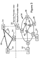
- FIG 3 shows a virtual service network (VSN) 30 covering a single transport domain.
- the VSN is a virtual overlay network between Access Media Gateways (AMG) 32 corresponding to a Service Access Points (SAP) 34 in VSN. It is owned by a service provider, who uses the VSN as infrastructure for the offering of end user services.
- the VSN offers the service to all end-users concentrated at one of the AMGs.
- the VSN SLA describes basically the VSN topology (number of SAPs, connectivity between the SAPs, e.g. full mesh-connectivity) and QoS characteristics between each set of reachable SAPs (throughput, maximum delay, etc).
- the lower tier of Figure 3 shows the transport network 36, including Edge Routers 38 via which the Access Media Gateways (AMG) are connected to networks and Core Routers 40 that interconnect the Edge Routers.
- AMG Access Media Gateways
- Core Routers 40 that interconnect the Edge Routers.
- ER Edge Routers
- P Core Routers
- DiffServ technology incorporating DiffServ Code Points (DSCP).
- the top tier of Figure 3 includes the virtual service network, interconnecting the Access Media Gateways 32 or SAPs 34 with QoS pipes.
- DiffServ offers well-defined QoS guarantees for packet aggregates, such as maximum delay or packet loss, between each pair of AMGs, thus yielding QoS-pipes 42 between AMGs 32.
- these QoS pipes 42 correspond to Service Level Specifications (SLSs).
- the QoS pipes 42 do not necessarily form a full mesh between all AMGs 32. This implies that communication between two AMGs attached to the same virtual service network might transit more than one QoS pipe (not shown in the Figure). Therefore, and to obtain QoS guarantees between each pair of SAPs, it is important that packets from a VSN are routed along the QoS pipes (SLSs) of their VSN. This requires that the routing decisions and forwarding of packets in Edge Routers and Core Routers need to be taken in the context of each VSN separately. This ensures that packets belonging to a particular VSN are routed along the QoS pipes that have been configured for that VSN, allowing e.g.
- RFC 2547 would be ideal for the present case but other VPN techniques would apply as well.
- Route and IP reachability exchange within a VSN is similar to that in VPNs.
- Access Media Gateways communicate their subnet address to the Edge Router via a routing protocol (e.g. Open Shortest Path First or BGP [Boarder Gateway Protocol] ) or via static configuration of the carrier.
- BGP Open Shortest Path First
- BGP BGP [Boarder Gateway Protocol]
- FIG 4 shows the peering or interconnection of two Virtual Service Networks 44 and 46. This allows for a larger geographical coverage and related user base for the offered (end-user) service. The goal is to obtain worldwide coverage, requiring any-to-any QoS connectivity amongst AMGs. This is obtained by interconnection of VSNs. Indeed, a single VSN has only local coverage. Although an IP VPN (and the corresponding VSN) may extend inter-domain including multiple transport domains (this is not shown in the Figures), an IP VPN can never interconnect all user aggregation points (AMGs). This would roughly require AMG-to-AMG pipes across the world, which yields an unscalable VPN. Therefore the peering of VSNs as shown in Figure 4 is an important embodiment of the solution.
- Service Providers owning a VSN, will set up peering agreements with other Service Providers. End-to-end flows connecting remote end-users likely travel along a concatenation of VSNs.
- SLSs or QoS pipes chain of service level specifications
- the VSNs need to peer at a well-defined point, called a peering point (PP) 47 corresponding to a Transit Access Point (TAP) 48.
- PP peering point
- TAP Transit Access Point
- the location of this peering point is part of the reachability agreement between the service providers.
- the physical location of the PP within the transport network infrastructure may be at the Border Routers (BR) 50 and 52 or at the link between Border Routers of neighboring transport domains.
- VSNs The confluence of VSNs at a peering point yields reachability amongst users at either side of the TAP.
- the virtual routing context of a VSN (present in all edge routers and the border router) knows reachability (routing) information about all of its own AMGs (analogously as in Figure 3).
- the VSN virtual routing context must also know the AMGs reachable in the peering VSNs and the AMGs that can be reached via this peering VSN.
- a VSN virtual routing context must know about all reachable AMGs in (directly) peering VSNs but also about AMGs in remote VSNs that can be reached via the peering VSN having its own peering points. This implies that if a VSN peers, it becomes part of a global inter-VSN network exactly like a stand-alone network becomes part of the Internet when it peers with a network which is already part of the Internet. This can be achieved by configuring the VPN routing protocols such that routing information from one VPN (VSN) is announced to another VPN. This is an important element of this embodiment and will be explained further in more details with reference to the Figure 6.
- FIG. 5 shows Virtual Service Network reference architecture, i.e. the proposed solution for the QoS problem described in Figure 1 above.
- the lower tier of Figure 5 shows three transport domains 60, 62 and 64.
- the left and the right domains are connected to access networks; i.e. their edge routers (ER) 66.1 and 66.2 are directly linked with end-user aggregator AMGs 68.1 and 68.2.
- ER edge routers
- AMGs end-user aggregator
- the middle domain 62 is shown as a transit domain, although also this domain could be connected to (non-shown) access networks.
- Each of these transport domains is controlled by an (ordinary) Network Management System (NMS) 70, 72 and 74.
- NMS Network Management System
- the NMS configures the (edge, core, and border) DiffServ routers 66.1, 70.1, 72.1, 72.2, 74.1 and 66.2. of the relevant domain by any means (e.g. Command Line Interface commands, Simple Network Management Protocol or Common Open Policy Server protocol).
- the edge and border routers of the domains are able to support several routing contexts, like for example the BGP/MPLS Virtual Routers [RFC 2547].
- the middle tier of Figure 5 shows the presence of three Virtual Service Networks 76, 78 and 80, as explained above.
- the first (second, etc) VSN owner leases capacity from the first (second, etc) network provider, which yields SLSs (or QoS pipes) between its AMGs and between any AMG 68.1 and 68.2 and the Peering Points 82 and 84.
- Any VSN SLA 86 between Service Provider and Network Provider also implies the presence of dedicated VSN virtual routing contexts in the edge and border routers ER and BR (lower tier in Figure 5).
- the Figure shows that the second (middle) VSN 78 has an SLS (or QoS pipe) between the two Peering Points.
- a first peering point 82 is located between the first 60 and the second 62 domains, whilst a second peering point 84 is located between the second 62 and the third 64 domains.
- AMGs attached to this domain and there might even be more connected transport domains, each with dedicated Peering Points.
- the presence of the Peering Points 82 and 84 is a consequence of the reachability agreements between VSN1-VSN2 and VSN2-VSN3 respectively. If no such mutual reachability agreement exists between two VSN owners, then there is no TAP corresponding to the peering point between the corresponding VSNs.
- the configuring of the VSN (or VPN) within the transport network is done by the NMS 70, 72 and 74 of the network provider.
- the control of the VSN itself i.e. the control of the leased resources amongst AMGs and between AMGs and peering point, is done by VSN Controllers (VSNC) 88, 90 and 92.
- the VSNC is owned by the owner of the VSN itself (the Service Provider) and it is a new functional element, dedicated to the VSN QoS solution.
- the VSNC may be part of an existing device such as a MultiMedia Call Server MMCS, or it may be a stand-alone device.
- the VSN Controller may be implemented in a centralized or a distributed fashion. In the former case one has e.g.
- VSN Controller per VSN (shown in figure 5). In the latter case one has multiple VSN Controllers for a single VSN, e.g. a VSN Controller at each Service Access Point (SAP) /Transit Access Point (TAP) of the VSN.
- SAP Service Access Point
- TAP Transit Access Point
- the NMS owned by the network provider, and the VSNC, owned by the service provider, share the same (contractual) information contained in the VSN SLA as has been referred to with reference to Figures 3 and 4.
- This information (SLSs or QoS pipes, topology, capacity, etc) is relatively static (typically days or months) compared to the relatively dynamic time scales of, e.g., call set-up and tear down of voice and video (typically minutes or hours).
- the NMS configures the transport network with this static information, a difficult task, but performed on a static basis.
- the VSNC installs this information in a VSNC database and will use this information for processing service (or call) requests making use of the (leased) VSN resources.
- a e.g.
- VSN SLA information containing, e.g., the full mesh of SLSs (QoS pipes) - and their capacity - between all Service Access Points.
- VSN SLA information is also distributed. For example the VSNC at the ingress SAP only "sees" the SLSs (or QoS pipes) starting at this SAP, i.e. this VSNC sees a "star of SLSs in stead of a full-mesh of SLSs.
- the NMS configures the network and the VSNC installs the virtual network information in the VSNC database.
- the routing information of the VSN must also be shared between transport and network provider equipment in the manner described below.
- the lower tier of Figure 5 also shows the presence of VSN virtual routing contexts (VR) in each edge and border router, as was explained in Figure 3.
- VSN VRs in the routers guarantee that packets (carrying a service served by the VSN) are routed along the SLSs or QoS pipes of that VSN, i.e., the routing decision of the packets is done within the VR context of the VSN.
- the same mechanism is used to guarantee the routing of packets between transport domains or border routers.
- the exchange of information between VRs of peering VSNs ensures that packets will travel along the SLS of one VSN towards the peering point and from the peering point onwards, the SLSs of the next VSN takes it over. It is important to note that if VSNs do not have a reachability agreement, then their VRs will not exchange routing information (across inter-domain links). A possible implementation of this mechanism is explained in Figures 6 and 7.
- the routing information of a dedicated VSN present in all of the VR contexts in edge and border routers carrying SLSs of the VSN, must be known by the VSN Controller VSNC. Indeed, the VSN controller must know about the sequence of SLSs (eventually both in its own VSN and in peering VSNs) that the packets will follow. Therefore the VSNC needs to be aware of the routing decisions that have been taken in the virtual routing context of the VSN. In fact, the basic routing requirements for the VSNC are twofold.
- the VSNC must be able to find the appropriate next VSNC, responsible for the resource admission control in the next VSN, if the destination can not be reached by it's own VSN. This may e.g. be fulfilled if the VSN Controller maintains a routing table, mapping each destination subnet mask to a "next hop" VSN controller if the destination is not in the same VSN.
- the second basic VSNC routing requirement is that the VSNC must be able to identify the ingress and egress points for the dataflow path as it traverses the Virtual Network
- the realization of this requirement depends on the VSNC implementation and the nature of the resource signaling mechanism. There are two extreme cases.
- the first case is a centralized VSNC implementation combined with out of band resource signaling, i.e. the resource signaling messages are not traveling along the routers on the data path.
- the VSNC which is not on the data path must nevertheless know about the information in the virtual routing tables of the VSN. This can, e.g., be realized by setting up a routing protocol session between one or more Edge Routers and the VSN controller. In this way, the VSN controller learns about the routes, which are advertised within the VSN context, and makes up its own routing table
- the second case is a distributed VSNC implementation ("living in the border router") combined with in-band signaling.
- the exchange of routing information - within virtual routing contexts -amongst VSNs is transferable across the domains. Taking for instance a case of three VSNs: VSN1, VSN2 and VSN3. If VSN1 and VSN2 have a reachability agreement and, as a consequence, exchange routing information, and if the same holds for VSN2 and VSN3, then automatically VSN1 knows about the routing information of VSN3. This is guaranteed by the operation of the routing protocols, as BGP (Boarder Gateway Protocol), themselves.
- BGP Battery Gateway Protocol
- the exchange of routing information is also relatively static (typically hours or days) compared with the more dynamic time scales of e.g. call set-up of voice and video.
- the routing information is exchanged amongst VR contexts of peering VSNs (and beyond) and this information is made available to the VSN Controllers.
- the VSNs are configured to accept user requests for QoS sensitive services (like voice, video, etc).
- FIG 5 shows at the left- and right-hand access networks which concentrate users.
- the AMGs are access concentrators and are directly connected to an Edge router of an IP transport domain (analogously as in Figure 1).
- an end-user 10 requests for, negotiates and eventually activates an end-user service by sending a request from its terminal to the application control server of the Service Provider SP via the MMCS 20.1.
- This can, e.g., be done by a call signaling protocol such as a Session Initiation Protocol [SIP] or H.323.
- SIP Session Initiation Protocol
- H.323 H.323.
- the user selects the service (by "clicking") on the portal website of the SP.
- the Service Provider SP may allocate to the user, i.e. the caller 10, a dedicated IP address for the duration of the service (or call).
- the address of the user's terminal may also be obtained at time of terminal configuration (e.g.
- the VSN solution is independent of the addressing issue, which might be private, public, IPv6, etc. The only requirement is that, within a VSN routing context, the user's IP address should be unique. Also during this initial call signaling phase, the caller 10 will retrieve the IP address of the called party 12 via a DNS like mechanism, based on the called party identifier. In summary, the call signaling protocol handles also mobility and roaming aspects as well as user authentication and authorization. All this is independent of the QoS problem as described by Figure 1.
- the user and service provider must also agree (during call set-up) on the QoS requirements of the service, such as required throughput, delay or packet-loss.
- This information can be exchanged in numerous ways between the user and SP.
- the QoS request could be "piggybacked" onto the call signaling protocol, e.g. SIP-SDP (Session Description Protocol).
- SIP-SDP Session Description Protocol
- the QoS requirements can be deduced from the codec type.
- the client selects the service (by "clicking") on the portal website of the SP and implicitly determines the QoS requirements.
- the user signals in-band its QoS requests to the AMG (by e.g. RSVP), which in turn pushes the information to the MMCS or responsible application server.
- the call resources signaling phase can start (see Figure 5).
- the call resource-signaling phase is initiated by the MMCS 20.1 (serving the caller), travels along the chain of VSNCs towards the MMCS 20.2 (serving the called party).
- the signaling protocol which is a dedicated protocol, can be in-band (the signaling is not traveling along the routers on the data-path) or out-of-band. It may also very well be a combination of both, e.g. some parts of the en-to-end path are controlled by a centralized (out-of-band) VSNC, while other parts may be controlled by distributed (in-band) VSNCs.
- the VSN Controller needs to process two things. First, the VSNC must check whether there are enough resources left in its own VSN to accommodate the flow. Second, the VSNC should eventually also forward the resource request to a peering VSN (VSNC) if the called party is not attached to its own VSN.
- VSNC peering VSN
- the VSN Based on the IP destination address of the called party, the VSN should determine on which sequence of SLSs or QoS pipes the flow will travel (in its own VSN). This implies that the VSN retrieves the ingress and egress SAP (or TAP).
- the ingress SAP can be retrieved based on the party that made the resource request: clients of a VSN should agree on a particular ingress SAP and should identify themselves when requesting resources from the VSN.
- TAP egress SAP
- the VSN In order to find the egress SAP (TAP), the VSN should find the next VSN and the peering point associated with that VSN. This is done based on a routing table that maps destination IP addresses to a next VSN.
- the VSN is also aware of the total capacity of the QoS pipes and the QoS guarantees as regards delay, jitter and the like for traffic aggregates within these QoS pipes (VSN SLA information).
- VSN SLA information When combined with the VSNs knowledge about all other ongoing calls in the QoS pipe, the VSN can perform resource admission control for the newly arriving call.
- the per-call admission control within a VSN is thus performed by the VSN Controller (VSNC 176).
- the VSNC has a view of the (leased) resources and topology of the VSN 60 by means of the VSN SLA 86 and handles the per-call resource signaling and admission.
- the VSN controller forwards the call request to the next hop VSN controller that needs to follow the same procedure, namely, determination of the next hop VSN, entry and exit point within its own VSN and admission control on the path between entry and exit point.
- the call request reaches the remote VSN 64 that serves the called party 12, the call request will be signaled back to the originating VSN 60 to perform the admission control on the backward path.
- the MMCS 20.1 will at the end acknowledge the call to the user and packets may start flowing.
- FIG. 6 and 7 illustrate the implementation of the VSN virtual routing contexts and the exchange of routing information between VSNs. While one embodiment of the invention utilizes on BGP/MPLS [RFC 2547] implementation, but extends it to links between different transport domains or - analogously - alternative embodiments include iBGP connections (RFC 2547) or eBGP connections.
- SLA Service providers want to offer their customers connectivity to a large set of subscribers.
- a single VSN manages a single transport domain, and hence, it can reach only a limited amount of subscribers. Therefore, the service provider establishes reachability SLAs with other service providers.
- SLA includes:
- Routing information can then be exchanged in the form of BGP messages. It is important that routing information is only passed upstream along the SLSs of a particular VSN. This ensures that the multimedia packets will only be routed along paths with pre-provisioned SLSs with strict delay and bandwidth guarantees and routing information is not passed along routes where the sequence of SLSs would be broken. This implies that the routing decisions for multimedia packets in the context of a VSN are different from for example the routing decisions for best-effort Internet traffic.
- One way to achieve the selective distribution of routes and separate routing tables for best-effort data and multimedia traffic is to use VPN techniques and Virtual Routers.
- Virtual routers can be configured such that they only install BGP routes from peering service providers with whom a reachability SLA has been established. Another advantage of virtual routers is that they enable the support of multiple service providers on a single transport network with each service provider having their own routing tables depending on the reachability SLAs they have.
- VSN can:
- Figure 6 shows how the SLSs of two peering VSNs 101 and 102 are concatenated and how the route information is propagated upstream the SLSs.
- the SLSs are enforced at the ingress point of the network.
- the SLSs of VSN 101 are enforced at respectively 103.1, 103.2 and 103.3.
- the two SLSs of VSN B are enforced at Border Router 2 (104).
- the border routers support virtual routers, which are L3 IP routers. This way, the connectionless and aggregate nature of IP technology is preserved. Between two virtual routers, packets will be forwarded by means of a tunneling mechanism. This can be achieved with e.g. MPLS, ATM or IP tunnels. It should be clearly noted that no end-to-end (MPLS) tunnels are setup, only intra-domain tunnels.
- MPLS end-to-end
- VSNs with BGP/MPLS VPNs will now be described.
- VSNs can be based on BGP/MPLS Virtual Private Networks (VPN) [RFC 2547] because they support the concept of virtual routers and the concept of L3 border routers that are connected to each other by MPLS tunnels. Hence, VSNs are implemented as overlay networks. Each VSN has its own routing table depending on the reachability SLAs it has.
- the traffic of a VSN is identified by means of an MPLS label. When traffic is forwarded between two virtual routers there may be MPLS switches in between which are not VSN aware. In this case two MPLS labels should be used. The inner label is used to identify which virtual router has to be used in the border router and the outer label is used to route the packet between the two border routers.
- Route distribution in VSNs can be done by means of BGP.
- a BGP speaker sends a messages to its peers to announce the routes.
- the BGP message that is exchanged contains, besides the IP addresses and path (attributes of "normal" BGP update messages), the following information (typical VPN/VSN attributes):
- Figure 7 explains how the routes are distributed and selectively installed in the virtual routers.
- the border router, 112, of VSN D, 111 will broadcast the BGP route announcements to all its peer networks, e.g., via, border routers 113, 114, 115.
- This message contains the IP address, path, VSN id and MPLS label.
- the VSN id is used in the virtual routers 113, 114, 115 of VSN A, B and C to check if they should install this route (i.e. if they have a reachability SLA with VSN D).
- VSN A and C ignore the BGP messages but VSN B, 110, installs the route and forwards the routes to its internal peers.
- VSN/MPLS VPN architecture from [RFC 2547bis], extended to eBGP connections, i.e. between border routers of two domains.
- Each Virtual Service Network should have a Virtual Service Network Controller that performs the functionality described above (centralized or distributed, in-band or out-of-band implementation).
- the VSNC When the VSNC receives a reservation request it performs an admission control. Therefore, it has to identify the correct SLS (or QoS pipe) over which the packet flow will be transported. Then the reservation request must eventually be forwarded to the next VSNC.
- the table look-up in the VSNC also yields the address of the next VSNC because the relation next hop VSN and the IP address of the VSNC are known from the reachability agreements amongst peering service providers.
- the VSNC In order to perform this routing function the VSNC has to determine what route the packets of the media flow (for which the reservation is being made) will follow. Hence, there is a need to install a routing table in the VSNC 120, 121, 122. This routing table must be synchronized with the routing tables of the (virtual) border routers 123, 124, 125. This can be achieved by making the VSNC a BGP speaker, or by configuring the VSNC as a "CE" (Customer Equipment) -device of the VPN. By creating a BGP connection 128 between the border router and the VSNC the routing information in the control plane (VSNC) is synchronized with the routing information in the transport plane (in the Virtual routers).
- CE Customer Equipment
Priority Applications (3)
| Application Number | Priority Date | Filing Date | Title |
|---|---|---|---|
| EP01403312A EP1331766A1 (de) | 2001-12-20 | 2001-12-20 | Système de télécommunications utilisant l'architecture d'un réseau de service virtuel |
| US10/322,622 US20030117954A1 (en) | 2001-12-20 | 2002-12-19 | Telecommunications system employing virtual service network architecture |
| CN02161139A CN1449162A (zh) | 2001-12-20 | 2002-12-20 | 使用虚拟业务网络结构的电信系统 |
Applications Claiming Priority (1)
| Application Number | Priority Date | Filing Date | Title |
|---|---|---|---|
| EP01403312A EP1331766A1 (de) | 2001-12-20 | 2001-12-20 | Système de télécommunications utilisant l'architecture d'un réseau de service virtuel |
Publications (1)
| Publication Number | Publication Date |
|---|---|
| EP1331766A1 true EP1331766A1 (de) | 2003-07-30 |
Family
ID=8183037
Family Applications (1)
| Application Number | Title | Priority Date | Filing Date |
|---|---|---|---|
| EP01403312A Withdrawn EP1331766A1 (de) | 2001-12-20 | 2001-12-20 | Système de télécommunications utilisant l'architecture d'un réseau de service virtuel |
Country Status (3)
| Country | Link |
|---|---|
| US (1) | US20030117954A1 (de) |
| EP (1) | EP1331766A1 (de) |
| CN (1) | CN1449162A (de) |
Cited By (1)
| Publication number | Priority date | Publication date | Assignee | Title |
|---|---|---|---|---|
| EP1708408A1 (de) † | 2004-01-20 | 2006-10-04 | Huawei Technologies Co., Ltd. | System und verfahren zur sicherstellung der dienstqualität in einem virtuellen privaten netzwerk |
Families Citing this family (109)
| Publication number | Priority date | Publication date | Assignee | Title |
|---|---|---|---|---|
| US7111163B1 (en) * | 2000-07-10 | 2006-09-19 | Alterwan, Inc. | Wide area network using internet with quality of service |
| US7111072B1 (en) | 2000-09-13 | 2006-09-19 | Cosine Communications, Inc. | Packet routing system and method |
| US7487232B1 (en) | 2000-09-13 | 2009-02-03 | Fortinet, Inc. | Switch management system and method |
| US7574495B1 (en) | 2000-09-13 | 2009-08-11 | Fortinet, Inc. | System and method for managing interworking communications protocols |
| US7272643B1 (en) * | 2000-09-13 | 2007-09-18 | Fortinet, Inc. | System and method for managing and provisioning virtual routers |
| US8250357B2 (en) | 2000-09-13 | 2012-08-21 | Fortinet, Inc. | Tunnel interface for securing traffic over a network |
| US7181547B1 (en) | 2001-06-28 | 2007-02-20 | Fortinet, Inc. | Identifying nodes in a ring network |
| US7203192B2 (en) | 2002-06-04 | 2007-04-10 | Fortinet, Inc. | Network packet steering |
| US7376125B1 (en) | 2002-06-04 | 2008-05-20 | Fortinet, Inc. | Service processing switch |
| US7177311B1 (en) * | 2002-06-04 | 2007-02-13 | Fortinet, Inc. | System and method for routing traffic through a virtual router-based network switch |
| US7161904B2 (en) | 2002-06-04 | 2007-01-09 | Fortinet, Inc. | System and method for hierarchical metering in a virtual router based network switch |
| US7171488B2 (en) * | 2002-07-03 | 2007-01-30 | International Business Machines Corporation | Managing data delivery in a data communications network |
| US7571206B2 (en) * | 2002-08-12 | 2009-08-04 | Equallogic, Inc. | Transparent request routing for a partitioned application service |
| US7096383B2 (en) | 2002-08-29 | 2006-08-22 | Cosine Communications, Inc. | System and method for virtual router failover in a network routing system |
| US7266120B2 (en) | 2002-11-18 | 2007-09-04 | Fortinet, Inc. | System and method for hardware accelerated packet multicast in a virtual routing system |
| US7461146B2 (en) * | 2003-01-20 | 2008-12-02 | Equallogic, Inc. | Adaptive storage block data distribution |
| US7627650B2 (en) * | 2003-01-20 | 2009-12-01 | Equallogic, Inc. | Short-cut response for distributed services |
| US8499086B2 (en) | 2003-01-21 | 2013-07-30 | Dell Products L.P. | Client load distribution |
| US8037264B2 (en) * | 2003-01-21 | 2011-10-11 | Dell Products, L.P. | Distributed snapshot process |
| US7127577B2 (en) * | 2003-01-21 | 2006-10-24 | Equallogic Inc. | Distributed snapshot process |
| US7937551B2 (en) | 2003-01-21 | 2011-05-03 | Dell Products L.P. | Storage systems having differentiated storage pools |
| US8254372B2 (en) | 2003-02-21 | 2012-08-28 | Genband Us Llc | Data communication apparatus and method |
| US7558844B1 (en) * | 2003-05-06 | 2009-07-07 | Juniper Networks, Inc. | Systems and methods for implementing dynamic subscriber interfaces |
| EP1623536B9 (de) * | 2003-05-15 | 2012-08-22 | TELEFONAKTIEBOLAGET LM ERICSSON (publ) | Methode für die verteilung des netzverkehrs entsprechend sla und qos betrachtungen |
| US7436840B1 (en) * | 2003-05-16 | 2008-10-14 | Sprint Communications Company L.P. | Network system manager for telecommunication carrier virtual networks |
| US7539135B1 (en) | 2003-05-16 | 2009-05-26 | Sprint Communications Company L.P. | System and method for establishing telecommunication carrier virtual networks |
| NO319422B1 (no) * | 2003-05-23 | 2005-08-08 | Tandberg Telecom As | Fremgangsmate for handtering av datahastighetsendringer |
| US7720095B2 (en) | 2003-08-27 | 2010-05-18 | Fortinet, Inc. | Heterogeneous media packet bridging |
| FI20031339A0 (fi) * | 2003-09-18 | 2003-09-18 | Nokia Corp | Menetelmä ja laite tiedon osoittamiseksi langattomassa verkossa |
| US7486684B2 (en) * | 2003-09-30 | 2009-02-03 | Alcatel-Lucent Usa Inc. | Method and apparatus for establishment and management of voice-over IP virtual private networks in IP-based communication systems |
| US7653730B1 (en) * | 2003-10-30 | 2010-01-26 | Sprint Communications Company L.P. | System and method for latency assurance and dynamic re-provisioning of telecommunication connections in a carrier virtual network |
| US7460526B1 (en) | 2003-10-30 | 2008-12-02 | Sprint Communications Company L.P. | System and method for establishing a carrier virtual network inverse multiplexed telecommunication connection |
| US7596612B1 (en) | 2003-11-25 | 2009-09-29 | Sprint Communications Company L.P. | Interface system for carrier virtual network system |
| US8027265B2 (en) * | 2004-03-19 | 2011-09-27 | Genband Us Llc | Providing a capability list of a predefined format in a communications network |
| US7990865B2 (en) * | 2004-03-19 | 2011-08-02 | Genband Us Llc | Communicating processing capabilities along a communications path |
| ATE528886T1 (de) * | 2004-06-30 | 2011-10-15 | Ericsson Telefon Ab L M | Verfahren und system zur konfiguration eines virtuellen privaten netzwerks mit mehreren domänen |
| US8150437B2 (en) * | 2004-09-09 | 2012-04-03 | Nextel Communications Company L.P. | Architecture to facilitate the monetization of disparate, inter-worked pushed to talk technologies |
| US7499419B2 (en) | 2004-09-24 | 2009-03-03 | Fortinet, Inc. | Scalable IP-services enabled multicast forwarding with efficient resource utilization |
| US8488612B2 (en) * | 2004-11-01 | 2013-07-16 | At&T Intellectual Property Ii, L.P. | System and method for method for providing quality-of service in a local loop |
| US7808904B2 (en) | 2004-11-18 | 2010-10-05 | Fortinet, Inc. | Method and apparatus for managing subscriber profiles |
| US7715395B2 (en) * | 2004-11-24 | 2010-05-11 | Microsoft Corporation | System and method for expanding the range of a mesh network |
| US7643483B2 (en) * | 2004-11-24 | 2010-01-05 | Microsoft Corporation | System and method for using a hop limited cast for internet egress point selection |
| US7593405B2 (en) * | 2004-12-09 | 2009-09-22 | Telefonaktiebolaget Lm Ericsson (Publ) | Inter-domain traffic engineering |
| US20060218353A1 (en) * | 2005-03-11 | 2006-09-28 | Interdigital Technology Corporation | Method and apparatus for implementing path-based traffic stream admission control in a wireless mesh network |
| US7609700B1 (en) | 2005-03-11 | 2009-10-27 | At&T Mobility Ii Llc | QoS channels for multimedia services on a general purpose operating system platform using data cards |
| US20090129386A1 (en) | 2005-04-29 | 2009-05-21 | Johan Rune | Operator Shop Selection |
| GB2427793B (en) | 2005-06-30 | 2010-02-17 | Vodafone Plc | Routing communications between telecommunications networks |
| US20070019568A1 (en) * | 2005-07-22 | 2007-01-25 | Sbc Knowledge Ventures, L.P. | Method of monitoring network elements supporting virtual private networks |
| US7657871B2 (en) | 2005-07-22 | 2010-02-02 | Sbc Knowledge Ventures, L.P. | Method and system of managing configuration profiles of a plurality of deployed network elements |
| US7778248B2 (en) * | 2005-10-28 | 2010-08-17 | Cisco Technology, Inc. | Method and apparatus for prioritized processing of routing information |
| US20070101018A1 (en) * | 2005-11-01 | 2007-05-03 | Meral Shirazipour | Inter-domain QoS reservation establishment and modification |
| US7978602B2 (en) * | 2005-11-14 | 2011-07-12 | Juniper Networks, Inc. | Dynamic construction of label switching protocol interfaces |
| US7668920B2 (en) * | 2006-03-01 | 2010-02-23 | Fortinet, Inc. | Electronic message and data tracking system |
| DE602006004338D1 (de) * | 2006-08-04 | 2009-01-29 | Alcatel Lucent | Vorrichtung, Modul und Verfahren zur Leitweglenkung für ein Zugangsnetz |
| US7664022B2 (en) | 2006-08-29 | 2010-02-16 | Cingular Wireless Ii, Llc | Policy-based service management system |
| CN101622711B (zh) | 2006-12-28 | 2012-07-18 | 杰恩邦德公司 | 用于无声插入描述符(sid)转换的方法、系统 |
| US7768923B2 (en) * | 2007-02-09 | 2010-08-03 | Cisco Technology, Inc. | Packet aging in a wireless network |
| WO2008136713A1 (en) * | 2007-05-08 | 2008-11-13 | Telefonaktiebolaget Lm Ericson (Publ) | Dynamic sla negotiation |
| CN101360037B (zh) * | 2007-08-03 | 2010-12-08 | 中国移动通信集团公司 | 数据业务网络系统及数据业务的访问方法 |
| US10063392B2 (en) | 2007-08-21 | 2018-08-28 | At&T Intellectual Property I, L.P. | Methods and apparatus to select a voice over internet protocol (VOIP) border element |
| US9258268B2 (en) | 2007-08-27 | 2016-02-09 | At&T Intellectual Property, I., L.P. | Methods and apparatus to dynamically select a peered voice over internet protocol (VoIP) border element |
| US9124603B2 (en) * | 2007-08-27 | 2015-09-01 | At&T Intellectual Property I., L.P. | Methods and apparatus to select a peered voice over internet protocol (VoIP) border element |
| CN101399766B (zh) * | 2007-09-28 | 2011-05-11 | 中国移动通信集团公司 | 数据业务的网络系统及访问方法 |
| WO2009070713A1 (en) * | 2007-11-29 | 2009-06-04 | Bigfoot Networks, Inc. | Remote message routing device and methods thereof |
| US9455924B2 (en) * | 2008-01-02 | 2016-09-27 | Media Network Services As | Device and system for selective forwarding |
| US8520663B2 (en) | 2008-02-26 | 2013-08-27 | At&T Intellectual Property I, L. P. | Systems and methods to select peered border elements for an IP multimedia session based on quality-of-service |
| US20100034196A1 (en) * | 2008-08-08 | 2010-02-11 | Kamala Prasad Das | RPH mapping and defaulting behavior |
| JP4647002B2 (ja) * | 2008-11-07 | 2011-03-09 | 株式会社エヌ・ティ・ティ・ドコモ | 移動端末及び通信制御方法 |
| US9692713B2 (en) * | 2008-11-12 | 2017-06-27 | Teloip Inc. | System, apparatus and method for providing a virtual network edge and overlay |
| KR101101614B1 (ko) | 2009-02-06 | 2012-01-02 | 한국외국어대학교 연구산학협력단 | 단대단 가상 홈 네트워크에서의 서비스 제어 시스템 및 방법 |
| US8908541B2 (en) | 2009-08-04 | 2014-12-09 | Genband Us Llc | Methods, systems, and computer readable media for intelligent optimization of digital signal processor (DSP) resource utilization in a media gateway |
| EP2299651A1 (de) * | 2009-09-17 | 2011-03-23 | Nokia Siemens Networks Oy | Verfahren und Vorrichtung zur Verarbeitung von Daten in einem IP-basierten Netzwerk |
| WO2011032595A1 (en) | 2009-09-18 | 2011-03-24 | Nokia Siemens Networks Gmbh & Co. Kg | Virtual network controller |
| US8484366B2 (en) * | 2010-01-05 | 2013-07-09 | Accenture Global Services Limited | Hierarchical service management |
| US8619780B1 (en) * | 2010-09-30 | 2013-12-31 | Amazon Technologies, Inc. | Processing packet routing information |
| WO2012055446A1 (en) * | 2010-10-29 | 2012-05-03 | Nokia Siemens Networks Gmbh & Co. Kg. | Dynamic creation of virtualized network topology |
| GB2485148B (en) * | 2010-11-01 | 2016-12-21 | Media Network Services | Network routing |
| EP2659622B1 (de) * | 2010-12-27 | 2016-03-09 | Telefónica, S.A. | Homegatewaysystem für den zugriff zu breitbanddienste |
| US20130114433A1 (en) | 2011-11-07 | 2013-05-09 | Qualcomm Incorporated | Scaling for fractional systems in wireless communication |
| GB2498517B (en) * | 2012-01-10 | 2019-02-27 | Media Network Services As | Data transport |
| GB2520451B (en) | 2012-03-20 | 2015-09-30 | Media Network Services As | Data distribution system |
| US9300570B2 (en) * | 2012-05-22 | 2016-03-29 | Harris Corporation | Multi-tunnel virtual private network |
| US9363204B2 (en) * | 2013-04-22 | 2016-06-07 | Nant Holdings Ip, Llc | Harmonized control planes, systems and methods |
| JP2014216812A (ja) * | 2013-04-25 | 2014-11-17 | 日本電気通信システム株式会社 | スイッチリソース制御システム及びスイッチリソース制御方法 |
| CN104168194B (zh) * | 2013-05-15 | 2018-01-02 | 华为技术有限公司 | 集群网络路径控制方法、设备和集群网络系统 |
| CN104579966B (zh) * | 2013-10-14 | 2018-08-17 | 华为技术有限公司 | 转发表项生成的方法、转发节点和控制器 |
| CN105830392B (zh) * | 2013-10-23 | 2020-07-31 | 瑞典爱立信有限公司 | 用于能够实现资源组件分配的方法、节点和计算机程序 |
| US9338094B2 (en) * | 2014-03-31 | 2016-05-10 | Dell Products, L.P. | System and method for context aware network |
| US10445339B1 (en) | 2014-05-28 | 2019-10-15 | EMC IP Holding Company LLC | Distributed contextual analytics |
| US9716660B2 (en) | 2014-12-11 | 2017-07-25 | Intel Corporation | Hierarchical enforcement of service flow quotas |
| US9930115B1 (en) | 2014-12-18 | 2018-03-27 | EMC IP Holding Company LLC | Virtual network storage function layer comprising one or more virtual network storage function instances |
| US10356169B1 (en) | 2014-12-23 | 2019-07-16 | EMC IP Holding Company LLC | Virtual content delivery network |
| US10778601B1 (en) | 2014-12-23 | 2020-09-15 | EMC IP Holding Company LLC | Automated assurance analysis providing feedback to orchestration of resources in virtualization infrastructure |
| US20160204916A1 (en) * | 2015-01-08 | 2016-07-14 | Ngoc-Dung DAO | System and method for joint optimization of source selection and traffic engineering |
| CN104753952A (zh) * | 2015-04-13 | 2015-07-01 | 成都双奥阳科技有限公司 | 基于虚拟机业务数据流的入侵检测分析系统 |
| US10111163B2 (en) | 2015-06-01 | 2018-10-23 | Huawei Technologies Co., Ltd. | System and method for virtualized functions in control and data planes |
| EP3257320B1 (de) | 2015-06-01 | 2020-04-08 | Huawei Technologies Co., Ltd. | System und verfahren für virtualisierte funktionen auf steuerungs- und datenebenen |
| US10313887B2 (en) | 2015-06-01 | 2019-06-04 | Huawei Technologies Co., Ltd. | System and method for provision and distribution of spectrum resources |
| US10700936B2 (en) | 2015-06-02 | 2020-06-30 | Huawei Technologies Co., Ltd. | System and methods for virtual infrastructure management between operator networks |
| US10212589B2 (en) | 2015-06-02 | 2019-02-19 | Huawei Technologies Co., Ltd. | Method and apparatus to use infra-structure or network connectivity services provided by 3rd parties |
| US20160373441A1 (en) * | 2015-06-16 | 2016-12-22 | Avaya Inc. | Providing secure networks |
| US9588815B1 (en) | 2015-06-17 | 2017-03-07 | EMC IP Holding Company LLC | Architecture for data collection and event management supporting automation in service provider cloud environments |
| US9769087B2 (en) * | 2015-08-03 | 2017-09-19 | Infinera Corporation | Providing ownership-based view and management of shared optical network resources |
| US10862818B2 (en) | 2015-09-23 | 2020-12-08 | Huawei Technologies Co., Ltd. | Systems and methods for distributing network resources to network service providers |
| WO2017080578A1 (en) * | 2015-11-09 | 2017-05-18 | Rwe Ag | System and method for transporting an object |
| CN111224857A (zh) * | 2016-06-29 | 2020-06-02 | 华为技术有限公司 | 用于实现组合虚拟专用网vpn的方法与装置 |
| CN106028453B (zh) * | 2016-07-01 | 2019-04-16 | 南京邮电大学 | 基于排队论的无线虚拟网络资源跨层调度映射方法 |
| KR102168047B1 (ko) | 2016-09-26 | 2020-10-20 | 난트 홀딩스 아이피, 엘엘씨 | 클라우드 네트워크들에서의 가상 회로들 |
| US10693715B1 (en) * | 2017-10-26 | 2020-06-23 | Amazon Technologies, Inc. | Dynamic network address space allocation for virtual networks |
Citations (4)
| Publication number | Priority date | Publication date | Assignee | Title |
|---|---|---|---|---|
| US5491694A (en) * | 1994-01-28 | 1996-02-13 | Cabletron Systems, Inc. | System and method for allocating a shared resource among competing devices |
| EP0952755A2 (de) * | 1998-03-27 | 1999-10-27 | Nec Corporation | Verfahren und Vorrichtung zur Bildung eines virtuellen Privatnetzes |
| WO2000031929A2 (en) * | 1998-11-25 | 2000-06-02 | Enron Warpspeed Services,Inc. | Method and apparatus for providing guaranteed quality/class of service within and across networks using existing reservation protocols and frame formats |
| US6085238A (en) * | 1996-04-23 | 2000-07-04 | Matsushita Electric Works, Ltd. | Virtual LAN system |
-
2001
- 2001-12-20 EP EP01403312A patent/EP1331766A1/de not_active Withdrawn
-
2002
- 2002-12-19 US US10/322,622 patent/US20030117954A1/en not_active Abandoned
- 2002-12-20 CN CN02161139A patent/CN1449162A/zh active Pending
Patent Citations (4)
| Publication number | Priority date | Publication date | Assignee | Title |
|---|---|---|---|---|
| US5491694A (en) * | 1994-01-28 | 1996-02-13 | Cabletron Systems, Inc. | System and method for allocating a shared resource among competing devices |
| US6085238A (en) * | 1996-04-23 | 2000-07-04 | Matsushita Electric Works, Ltd. | Virtual LAN system |
| EP0952755A2 (de) * | 1998-03-27 | 1999-10-27 | Nec Corporation | Verfahren und Vorrichtung zur Bildung eines virtuellen Privatnetzes |
| WO2000031929A2 (en) * | 1998-11-25 | 2000-06-02 | Enron Warpspeed Services,Inc. | Method and apparatus for providing guaranteed quality/class of service within and across networks using existing reservation protocols and frame formats |
Cited By (2)
| Publication number | Priority date | Publication date | Assignee | Title |
|---|---|---|---|---|
| EP1708408A1 (de) † | 2004-01-20 | 2006-10-04 | Huawei Technologies Co., Ltd. | System und verfahren zur sicherstellung der dienstqualität in einem virtuellen privaten netzwerk |
| EP1708408B2 (de) † | 2004-01-20 | 2012-05-23 | Huawei Technologies Co., Ltd. | System und verfahren zur sicherstellung der dienstqualität in einem virtuellen privaten netzwerk |
Also Published As
| Publication number | Publication date |
|---|---|
| CN1449162A (zh) | 2003-10-15 |
| US20030117954A1 (en) | 2003-06-26 |
Similar Documents
| Publication | Publication Date | Title |
|---|---|---|
| EP1331766A1 (de) | Système de télécommunications utilisant l'architecture d'un réseau de service virtuel | |
| US8929394B2 (en) | End-to-end service quality for latency-intensive internet protocol (IP) applications in a heterogeneous, multi-vendor environment | |
| EP1282995B1 (de) | Policyserver und architektur zur bereitstellung von zuteilungsregeln für funknetzwerkressourcen | |
| US8458332B2 (en) | Multiplexing several individual application sessions over a pre-allocated reservation protocol session | |
| US7561586B2 (en) | Method and apparatus for providing network VPN services on demand | |
| US8411564B2 (en) | Architectural framework of communication network and a method of establishing QOS connection | |
| US6714987B1 (en) | Architecture for an IP centric distributed network | |
| US20090116382A1 (en) | Resource and admission control subsystem and method thereof in ngn | |
| US20040223500A1 (en) | Communications network with converged services | |
| US20020062376A1 (en) | QoS server and control method for allocating resources | |
| US20070147243A1 (en) | Method and system for guaranteeing end-to-end quality of service | |
| US7266683B1 (en) | Selective encryption of application session packets | |
| US9485176B2 (en) | Global IP-based service-oriented network architecture | |
| Fang et al. | Interprovider IP-MPLS services: requirements, implementations, and challenges | |
| Callejo-Rodrigitez et al. | EuQoS: end-to-end QoS over heterogeneous networks | |
| Le Faucheur | Aggregation of Resource ReSerVation Protocol (RSVP) Reservations over MPLS TE/DS-TE Tunnels | |
| Kim et al. | Session and connection management for QoS-guaranteed multimedia service provisioning on IP/MPLS networks | |
| Kim | Inter-AS session & connection management for QoS-guaranteed DiffServ provisioning | |
| Sijben et al. | Application‐level control of IP networks: IP beyond the Internet | |
| WO2004042533A2 (en) | End-to-end qos internet protocol | |
| Ghazel et al. | An improved model for next generation networks with guaranteed end-to-end quality of service | |
| Sargento et al. | IP access networks with QoS support | |
| IP | Call Admission Control | |
| Mogale | Quality of Service in IP Networks | |
| Terzis et al. | A Two-Tier Resource Management Model for Differentiated Services Networks |
Legal Events
| Date | Code | Title | Description |
|---|---|---|---|
| PUAI | Public reference made under article 153(3) epc to a published international application that has entered the european phase |
Free format text: ORIGINAL CODE: 0009012 |
|
| AK | Designated contracting states |
Designated state(s): AT BE CH CY DE DK ES FI FR GB GR IE IT LI LU MC NL PT SE TR |
|
| AX | Request for extension of the european patent |
Extension state: AL LT LV MK RO SI |
|
| 17P | Request for examination filed |
Effective date: 20040130 |
|
| AKX | Designation fees paid |
Designated state(s): AT BE CH CY DE DK ES FI FR GB GR IE IT LI LU MC NL PT SE TR |
|
| 17Q | First examination report despatched |
Effective date: 20060517 |
|
| RAP1 | Party data changed (applicant data changed or rights of an application transferred) |
Owner name: ALCATEL LUCENT |
|
| STAA | Information on the status of an ep patent application or granted ep patent |
Free format text: STATUS: THE APPLICATION HAS BEEN WITHDRAWN |
|
| 18W | Application withdrawn |
Effective date: 20070414 |