EP1331706A2 - Insulation displacement apparatus - Google Patents
Insulation displacement apparatus Download PDFInfo
- Publication number
- EP1331706A2 EP1331706A2 EP03250415A EP03250415A EP1331706A2 EP 1331706 A2 EP1331706 A2 EP 1331706A2 EP 03250415 A EP03250415 A EP 03250415A EP 03250415 A EP03250415 A EP 03250415A EP 1331706 A2 EP1331706 A2 EP 1331706A2
- Authority
- EP
- European Patent Office
- Prior art keywords
- die
- guards
- insulation displacement
- connector
- contacts
- Prior art date
- Legal status (The legal status is an assumption and is not a legal conclusion. Google has not performed a legal analysis and makes no representation as to the accuracy of the status listed.)
- Granted
Links
Images


Classifications
-
- H—ELECTRICITY
- H01—ELECTRIC ELEMENTS
- H01R—ELECTRICALLY-CONDUCTIVE CONNECTIONS; STRUCTURAL ASSOCIATIONS OF A PLURALITY OF MUTUALLY-INSULATED ELECTRICAL CONNECTING ELEMENTS; COUPLING DEVICES; CURRENT COLLECTORS
- H01R43/00—Apparatus or processes specially adapted for manufacturing, assembling, maintaining, or repairing of line connectors or current collectors or for joining electric conductors
- H01R43/01—Apparatus or processes specially adapted for manufacturing, assembling, maintaining, or repairing of line connectors or current collectors or for joining electric conductors for connecting unstripped conductors to contact members having insulation cutting edges
Definitions
- the present invention relates to an insulation displacement apparatus constructed such that unbared electric wire ends will be pressed into the respective wire end-receiving receptacle portions of a contact so as to establish a forced and direct electric connection between each wire end and each receptacle portion.
- Each contact of a connector handled in and by any insulation displacement apparatus of this type does comprise a receptacle portion made of a flat piece of metal plate.
- This receptacle portion has a pair of piercing blades facing one another and defining between them a slot for receiving an unbared wire end covered with an insulation layer. With a punch pressing the wire end into this slot, its blades will make slits in the insulation layer so that the wire end is exposed in part and gripped fixedly due to a moderate force which those blades apply to said wire end.
- the means for prevention of an excessive widening of said receptacle portions comprised guide walls or guide pins disposed in and along both the sides of a punch reciprocating vertically to press the wire ends into the receptacle portions.
- These guide walls or pins were intended to bear sideways against a pair of partitions defining between them one receptacle portion.
- the connector comprises two or more insulation displacement type contacts, then the punch or the apparatus itself will become complicated to an undesirable degree. It may be very intricate or almost difficult to replace the pressing punch with another whenever the number of contacts changes. Further, it is an inevitable problem that relevant parts of such an apparatus become considerably expensive.
- the present invention was made to address the drawbacks inherent in the prior art structures.
- an insulation displacement apparatus comprising a means for protecting the insulation displacement receptacle portions of a connector from being widened, wherein this means is disposed in an insulation displacing stationary die that operates to temporarily hold therein the connector.
- Such a means employed in this invention has to be concise in its overall structure, easy to be replaced with another compatible one, and must be composed of simpler and inexpensive constituent parts.
- the present invention will provide an insulation displacement apparatus comprising an insulation displacing stationary die for holding in place a connector that comprises an insulated housing and a plurality of contacts each having a receptacle portion, with the contacts being individually held in compartments that are formed in the insulated housing.
- the apparatus further comprises an insulation displacing punch facing the die and driven to press unbared wire ends into the receptacle portions so as to establish electric connection between each wire end and each receptacle portion.
- the apparatus provided herein is however characterized in that a pair of upright guards are disposed in the die so as to protect the receptacle portions from being widened during an insulation displacement operation, with the upright guards being spaced from each other a distance substantially equal to the sideways width of the insulated housing, so that end walls of the housing are propped up by the guards sideways from the outside while the insulation displacement operation is being carried out.
- the insulation displacement apparatus of the invention may be constructed such that the upright guards protrude integrally from opposite ends of a supporting plate capable of moving up and down in the die, so that upon delivery of the connector to be held in place on the die, the supporting plate will be driven upwards to cause its upright guards to prop up the end walls of the housing sideways and from the outside.
- the supporting plate is of a sideways width corresponding to multiple polarities of the punch having a plurality of pressing teeth integral therewith. If each connector has multiple polarities whose number is equal to the number of pressing teeth which the insulation displacing punch comprises, then the upright guards will be disposed at opposite ends of the supporting plate. In another case wherein each connector has a less number of polarities than the punch, one of the upright guards will be formed to be broader than the other so as to adjust a distance between them to correspond to the width of insulated housing of each connector. Further in this case, relief grooves will be engraved in the top of such a broadened upright guard so that idle teeth not pressing the wire ends are allowed to loosely fit in those relief grooves.
- one and the same insulation displacing punch can be used even if connectors having any different number of polarities are fed to the stationary die, by merely and simply replacing the supporting plate with another one. Now, a noticeably reduced number of constituent parts will suffice well to conduct easily and inexpensively the insulation displacement operation for electric connection.
- Figs. 1 and 2 show an insulation displacement type connector 1 to which a group of unbared wire ends (see Fig. 3) will be secured using an apparatus of the present invention.
- the connector 1 comprises an insulated housing 2 and a plurality of insulation displacement type contacts 3 accommodated therein.
- Each compartment vertically extending to have an open top and an open bottom is defined between two adjacent ones of intermediate partitions 5, or between one of the outermost partitions 5 and one of end walls 6.
- Each partition 5 is of a thickness 'a' that is large as twice as that 'b' of each end wall 6. Owing to this feature, if two or more connectors 1 are placed side by side in a die (detailed later) of this apparatus, all the contacts 3 will take their positions arranged at regular intervals. All of the wire ends 15 can thus be pressed simultaneously at a stroke into the respective connectors 1, conveniently to the insulation displacement type operation.
- Each compartment 4 has a recess 7 formed as a frontal region of its open top so as to support the wire end 15.
- Each contact 3 is a piece punched off a thin conductive metal plate and bent into a designed shape.
- a mating connector (not shown) will engage with a contacting portion 8 of this contact 3, whose top continues to a receptacle portion 9.
- the receptacle portion 9 comprises a pair of flat blades 10 and 10, each having a U-shaped slot 11 into which the unbared wire end 15 will be forced.
- Such contacts 3 held in the respective compartments 4 are insulated from each other.
- Figs. 3 and 4 show the principal parts of the apparatus of the invention, wherein an insulation displacing stationary die 21 temporarily holds the connector or connectors 1 intermittently fed to the apparatus.
- An insulation displacing punch 22 disposed above and facing the die 21 is another principal part of this apparatus, and both the die and punch 22 are driven up and down by an actuator not shown.
- the die 21 has a movable shoe 23 and a spring 24 urging this shoe in such a direction that the connector or connectors 1 will be retained at a pressing position.
- a further spring 26 biases a wire holding-down guide 25 of the punch 22 to slide up and down in the punch.
- the punch 22 has twelve pressing teeth 27.
- this punch may be replaced with any other one 22 that has a different number of pressing teeth 27 corresponding to the number of polarities of the connector 1.
- the die 21 has a pair of upright guards 31 and 32 so as to inhibit the receptacle portions 9 of contacts 3 from being widened during the insulation displacement process.
- these guards 31 and 32 integrally protrude from opposite lateral end regions of a supporting plate 33.
- the two upright guards 31 and 32 are shaped and sized to match connectors 1 whose number of polarities is seven (7).
- a distance 'd' between these guards 31 and 32 is substantially the same as the sideways width of each connector.
- the one guard 31 of an increased width has a top with five relief grooves 34 to loosely receive the five idle pressing teeth 27 not functioning to press the wire ends in this mode.
- FIG. 6 shows another example adapted for other enlarged connectors 1 whose number of polarities is twelve (12), wherein the distance 'D' between those upright guards 31 and 32 is substantially equal to sideways width of such enlarged connectors.
- two unit connectors 61 each having six polarities are arranged side by side on the die 21 so as to work as a whole as a twelve polarity connector 1.
- thickness 'b' of each end wall 6 of each unit connector 61 is half of that 'd' of each partition 5. Therefore, all the contacts 3 of such two connectors 61 are arranged at regular intervals, as if a single twelve-polarity connector 1 is subject to processing.
- the supporting plate 33 having the upright guards 31 and 32 erected thereon is placed in a slot 28 formed in the die 21.
- This plate 33 extending through the slot 28 is capable of a sliding displacement therein in a vertical direction.
- an actuator 35 such as a pneumatic cylinder raises this plate such that its guards 31 and 32 will bear against the opposite end walls 6 and 6.
- the connector 1 or 61 is gripped at both the side faces of its insulated housing 2, lest any of its end walls 6 should be distorted or inclined to widen the receptacle portions.
- the upright guards 31 and 32 are preferably formed integral with opposite end regions of the supporting plate 33. This structure will reduce the number of constituent parts and lower manufacture cost of this apparatus, although they may alternatively be prepared as discrete parts.
- a connector feeder not shown will deliver a connector 1 to the die 21 to be held in position shown in Figs. 3 and 7, before the pneumatic cylinder 35 lifts the supporting plate 33. As a result, its guards 31 and 32 come into contact with the end walls 6 to thereby grip this connector as shown in Figs 4 and 8.
- seven lengths of electric wires 15 from a wire feeder not shown are set in position above and facing the seven polarities, viz., seven contacts 3 of this connector.
- the punch 22 will subsequently be driven to descend as seen in Fig. 9 so that its pressing teeth 27 facing the respective contacts do force the wire ends 15 at once into the receptacle portions 9.
- the two slots 11 belonging to each receptacle portion 9 will thus receive one of the wire ends.
- Edges serving as blades facing one another to define each slot 11 do consequently pierce the insulation layer of wire end. Slits thus produced in the insulation layer are effective to expose in part a conductive core of this wire end, such that the blades 10 grip it with a moderate force. In this manner, the unbared wire ends 15 are directly brought into electric connection to the respective contacts 3. Idle teeth 27 not pressing the wire ends loosely fit in the relief grooves 34 formed in the supporting plate 31. The force applied to each wire end 15 and thrusting it into the slots 11 will tend to deform and widen the receptacle portion 9. However, intermediate ones of contacts 3 located not at but between opposite ends of the insulated housing 2 will not suffer from any adverse effect to become inclined due to such a thrust.
- each partition 5 intervening between the two adjacent compartments 4 receives such a force's portions acting in opposite directions and thus canceling one another.
- Each contact 3 located at one of the side ends of insulated housing 2 tends to incline the end wall 6, but it is propped up inwardly by the upright guard 31 or 32 so as not to become inclined or collapsed to widen the receptacle portion 9. All the receptacle portions 9 of the intermediate and sideways-end contacts 3 are thus protected from being widened.
- the punch 22 Upon completion of the insulation displacement process for connecting the unbared wire ends 15 to the connector 1, the punch 22 will be raised upwards away from the die 21 as seen in Fig. 10. However, the end walls 6 and 6 of this connector 1 at this step still remain gripped with the upright guards 31 and 32, it will be held in place not to accompany the rising punch 22. Subsequent to such a removal of the punch 22, the supporting plate 33 will be lowered to free the end walls of the connector 1, thereby making it possible to eject it together with the wire ends 15, out of the die 21.
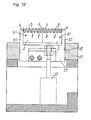
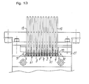
- Figs. 12 and 13 show a case wherein the supporting plates 33 with it upright guards 31 and 32 arranged to match a twelve-polarity connector as shown in Fig. 6.
- two six-polarity connectors 61 will be set in position side by side on the die 21 so that the twelve unbared wire ends 15 are put into insulation displacement connection at once to both the connectors 61. All of their contacts 3 will be protected from deformation otherwise causing them to be widened, in a manner similarly to the preceding embodiment.
- the connector delivered to the die is propped up at its end walls by the pair of upright guards, during the insulation displacement process. These end walls are protected from falling or deformation, thus inhibiting the sideways-end contacts adjacent to them from widening their receptacle portions.
- the intermediate contacts each located between the adjacent partitions are also protected spontaneously and surely from such a widening deformation of their receptacle portions. This is because, as noted above, each partition between the two adjacent compartments receives two forces of the same strength but acting in opposite directions to cancel one another. The receptacle portions of all contacts will now be protected in a reliable manner from the widening deformation.
- the one and the same punch may be used in combination with a few or several supporting plates whose pairs of upright guards are spaced different distances from each other. By replacing the supporting plate with another one, this apparatus can operate efficiently for various connectors having different numbers of polarities.
Landscapes
- Engineering & Computer Science (AREA)
- Manufacturing & Machinery (AREA)
- Connections By Means Of Piercing Elements, Nuts, Or Screws (AREA)
- Multi-Conductor Connections (AREA)
- Manufacturing Of Electrical Connectors (AREA)
- Connector Housings Or Holding Contact Members (AREA)
Abstract
Description
Claims (2)
- An insulation displacement apparatus comprising: an insulation displacing stationary die (21) for holding in place a connector (1) that comprises an insulated housing (2) and a plurality of contacts (3) each having a receptacle portion (9), with the contacts (3) being individually held in compartments (4) that are formed in the insulated housing (2), and an insulation displacing punch (22) facing the die (21) and drivable to press unbared wire ends (15) into the receptacle portions (9) so as to establish electric connection between each wire end (15) and each receptacle portion (9),
characterized in that a pair of upright guards (31,32) are disposed in the die (21) so as to protect the receptacle portions (9) from being widened during an insulation displacement operation, with the upright guards (31,32) being spaced from each other a distance (d, D) substantially equal to the sideways width of the insulated housing (2), so that end walls (6,6) of the housing are propped up by the guards (31,32) sideways from the outside while the insulation displacement operation is being carried out. - An insulation displacement apparatus as defined in claim 1, characterized in that the upright guards (31, 32) protrude integrally from opposite ends of a supporting plate (33) capable of moving up and down in the die (21), so that upon delivery of the connector (1) to be held in place on the die, the supporting plate (33) will be driven upwards to cause its upright guards (31,32) to prop up the end walls (6,6) of the housing (2) sideways and from the outside.
Applications Claiming Priority (2)
| Application Number | Priority Date | Filing Date | Title |
|---|---|---|---|
| JP2002015683 | 2002-01-24 | ||
| JP2002015683A JP3607679B2 (en) | 2002-01-24 | 2002-01-24 | Pressure welding device |
Publications (3)
| Publication Number | Publication Date |
|---|---|
| EP1331706A2 true EP1331706A2 (en) | 2003-07-30 |
| EP1331706A3 EP1331706A3 (en) | 2004-08-18 |
| EP1331706B1 EP1331706B1 (en) | 2006-12-13 |
Family
ID=19191960
Family Applications (1)
| Application Number | Title | Priority Date | Filing Date |
|---|---|---|---|
| EP03250415A Expired - Lifetime EP1331706B1 (en) | 2002-01-24 | 2003-01-23 | Insulation displacement apparatus |
Country Status (4)
| Country | Link |
|---|---|
| US (1) | US6676437B2 (en) |
| EP (1) | EP1331706B1 (en) |
| JP (1) | JP3607679B2 (en) |
| DE (1) | DE60310277T2 (en) |
Families Citing this family (3)
| Publication number | Priority date | Publication date | Assignee | Title |
|---|---|---|---|---|
| JP4259992B2 (en) * | 2003-12-01 | 2009-04-30 | 矢崎総業株式会社 | Pressure welding structure and pressure welding jig |
| DE102008033905A1 (en) | 2008-07-18 | 2010-01-21 | Wago Verwaltungsgesellschaft Mbh | Conductor connection element for attaching electrical conductor, has sharp-edged insulation cuts that are aligned at angle which is less than angle at which contact-cuts are aligned with respect to longitudinal extension axis of slot |
| JP6188507B2 (en) * | 2013-09-10 | 2017-08-30 | 株式会社ニチフ端子工業 | Wire branch connector |
Family Cites Families (11)
| Publication number | Priority date | Publication date | Assignee | Title |
|---|---|---|---|---|
| JPS62202471A (en) * | 1986-02-07 | 1987-09-07 | 富士通株式会社 | Connector and manufacture of the same |
| US5338220A (en) * | 1992-05-19 | 1994-08-16 | The Whitaker Corporation | Electrical connector housing assembly and an electrical terminal therefor |
| US5363549A (en) * | 1993-07-30 | 1994-11-15 | E. D. Design Manufacturing | Cable laminating and terminating system |
| JPH07272815A (en) | 1994-02-14 | 1995-10-20 | Yazaki Corp | Method and apparatus for crimping terminal wire |
| US6017237A (en) * | 1996-08-26 | 2000-01-25 | Sullivan; Robert W. | Twisted-pair data cable with electrical connector attached |
| JP3303724B2 (en) | 1997-05-27 | 2002-07-22 | 住友電装株式会社 | Pressure welding method of electric wires to connectors and terminal fittings |
| JP3334100B2 (en) * | 1997-05-29 | 2002-10-15 | 矢崎総業株式会社 | Connector housing |
| JP3454709B2 (en) * | 1998-04-07 | 2003-10-06 | 矢崎総業株式会社 | ID connector |
| US6123566A (en) * | 1998-12-21 | 2000-09-26 | Lucent Technologies Inc. | Terminal strip with integrated strain relief mechanism for an insulation displacement connector |
| JP3331185B2 (en) | 1999-03-19 | 2002-10-07 | タイコエレクトロニクスアンプ株式会社 | Pressure welding device and pressure welding method |
| US6475019B1 (en) * | 2001-07-12 | 2002-11-05 | Leviton Manufacturing Co., Inc. | Insulation displacement electrical connector |
-
2002
- 2002-01-24 JP JP2002015683A patent/JP3607679B2/en not_active Expired - Fee Related
- 2002-12-27 US US10/329,374 patent/US6676437B2/en not_active Expired - Fee Related
-
2003
- 2003-01-23 DE DE60310277T patent/DE60310277T2/en not_active Expired - Fee Related
- 2003-01-23 EP EP03250415A patent/EP1331706B1/en not_active Expired - Lifetime
Also Published As
| Publication number | Publication date |
|---|---|
| DE60310277D1 (en) | 2007-01-25 |
| JP3607679B2 (en) | 2005-01-05 |
| EP1331706A3 (en) | 2004-08-18 |
| DE60310277T2 (en) | 2007-06-21 |
| JP2003217783A (en) | 2003-07-31 |
| US6676437B2 (en) | 2004-01-13 |
| EP1331706B1 (en) | 2006-12-13 |
| US20030139075A1 (en) | 2003-07-24 |
Similar Documents
| Publication | Publication Date | Title |
|---|---|---|
| EP0039569B1 (en) | Electrical plug receptacle connector | |
| EP0793303A2 (en) | Electrical connector with terminals of varying lengths | |
| EP0034433A2 (en) | An electrical connector, a method of gang terminating electrical conductors and apparatus for carrying out the method | |
| JPS581520B2 (en) | Dense Connector Fake Tsuzokusurouchi | |
| US20030216085A1 (en) | Terminal fitting and a method of forming it | |
| US4127935A (en) | Method for assembly of electrical connectors | |
| US8251737B2 (en) | Terminal block for a cable connector | |
| US5636438A (en) | Connecting terminal cutting and crimping method and apparatus | |
| US6676437B2 (en) | Insulation displacement apparatus | |
| US5951321A (en) | Multipin connector assembly | |
| JPS58123686A (en) | Both end pressing machine for pressure contact connector | |
| EP0057780A1 (en) | Electrical connector with a terminal having a slotted wire receiving portion and wire strain relief means | |
| US4690477A (en) | Electrical connector apparatus | |
| JP4613187B2 (en) | Caulking jig and caulking method between cable and holding member | |
| FI67458C (en) | ELEKTRISKT KONTAKTDON MED STICKKONTAKT OCH STICKDOSA OCH FOERFARANDE FOER DESS FRAMSTAELLNING | |
| KR100846849B1 (en) | Terminal Forming Apparatus and Method | |
| US6626693B2 (en) | Metal terminal and method of forming metal terminal | |
| US5632081A (en) | Two step tab crimper and wire inserter | |
| JP2000340332A (en) | Pressure connecting device and pressure connecting method | |
| EP0812033A2 (en) | Receptacle contacts and method of manufacture | |
| JP2002292440A (en) | Manufacturing method of clamp spring | |
| EP2169784A2 (en) | Connector terminal structure, connector and method of assembling connector | |
| EP0200517B1 (en) | Electrical connector assembly | |
| EP0621985B1 (en) | Assembly of miniature connector system | |
| JP3665281B2 (en) | Wire pressure welding device with wire guide |
Legal Events
| Date | Code | Title | Description |
|---|---|---|---|
| PUAI | Public reference made under article 153(3) epc to a published international application that has entered the european phase |
Free format text: ORIGINAL CODE: 0009012 |
|
| AK | Designated contracting states |
Designated state(s): AT BE BG CH CY CZ DE DK EE ES FI FR GB GR HU IE IT LI LU MC NL PT SE SI SK TR |
|
| AX | Request for extension of the european patent |
Extension state: AL LT LV MK RO |
|
| PUAL | Search report despatched |
Free format text: ORIGINAL CODE: 0009013 |
|
| AK | Designated contracting states |
Kind code of ref document: A3 Designated state(s): AT BE BG CH CY CZ DE DK EE ES FI FR GB GR HU IE IT LI LU MC NL PT SE SI SK TR |
|
| AX | Request for extension of the european patent |
Extension state: AL LT LV MK RO |
|
| RIC1 | Information provided on ipc code assigned before grant |
Ipc: 7H 01R 43/01 A Ipc: 7H 01R 4/24 B |
|
| 17P | Request for examination filed |
Effective date: 20050214 |
|
| AKX | Designation fees paid |
Designated state(s): DE GB IT |
|
| 17Q | First examination report despatched |
Effective date: 20050602 |
|
| RBV | Designated contracting states (corrected) |
Designated state(s): DE GB IT |
|
| GRAP | Despatch of communication of intention to grant a patent |
Free format text: ORIGINAL CODE: EPIDOSNIGR1 |
|
| GRAS | Grant fee paid |
Free format text: ORIGINAL CODE: EPIDOSNIGR3 |
|
| GRAA | (expected) grant |
Free format text: ORIGINAL CODE: 0009210 |
|
| AK | Designated contracting states |
Kind code of ref document: B1 Designated state(s): DE GB IT |
|
| PG25 | Lapsed in a contracting state [announced via postgrant information from national office to epo] |
Ref country code: IT Free format text: LAPSE BECAUSE OF FAILURE TO SUBMIT A TRANSLATION OF THE DESCRIPTION OR TO PAY THE FEE WITHIN THE PRESCRIBED TIME-LIMIT;WARNING: LAPSES OF ITALIAN PATENTS WITH EFFECTIVE DATE BEFORE 2007 MAY HAVE OCCURRED AT ANY TIME BEFORE 2007. THE CORRECT EFFECTIVE DATE MAY BE DIFFERENT FROM THE ONE RECORDED. Effective date: 20061213 |
|
| REG | Reference to a national code |
Ref country code: GB Ref legal event code: FG4D |
|
| REF | Corresponds to: |
Ref document number: 60310277 Country of ref document: DE Date of ref document: 20070125 Kind code of ref document: P |
|
| PLBE | No opposition filed within time limit |
Free format text: ORIGINAL CODE: 0009261 |
|
| STAA | Information on the status of an ep patent application or granted ep patent |
Free format text: STATUS: NO OPPOSITION FILED WITHIN TIME LIMIT |
|
| 26N | No opposition filed |
Effective date: 20070914 |
|
| PGFP | Annual fee paid to national office [announced via postgrant information from national office to epo] |
Ref country code: DE Payment date: 20090326 Year of fee payment: 7 |
|
| PG25 | Lapsed in a contracting state [announced via postgrant information from national office to epo] |
Ref country code: DE Free format text: LAPSE BECAUSE OF NON-PAYMENT OF DUE FEES Effective date: 20100803 |
|
| PGFP | Annual fee paid to national office [announced via postgrant information from national office to epo] |
Ref country code: GB Payment date: 20110114 Year of fee payment: 9 |
|
| GBPC | Gb: european patent ceased through non-payment of renewal fee |
Effective date: 20120123 |
|
| PG25 | Lapsed in a contracting state [announced via postgrant information from national office to epo] |
Ref country code: GB Free format text: LAPSE BECAUSE OF NON-PAYMENT OF DUE FEES Effective date: 20120123 |