EP1331702A2 - Coaxial cable connector - Google Patents
Coaxial cable connector Download PDFInfo
- Publication number
- EP1331702A2 EP1331702A2 EP03250438A EP03250438A EP1331702A2 EP 1331702 A2 EP1331702 A2 EP 1331702A2 EP 03250438 A EP03250438 A EP 03250438A EP 03250438 A EP03250438 A EP 03250438A EP 1331702 A2 EP1331702 A2 EP 1331702A2
- Authority
- EP
- European Patent Office
- Prior art keywords
- connector
- cable
- housing
- open ended
- ended recess
- Prior art date
- Legal status (The legal status is an assumption and is not a legal conclusion. Google has not performed a legal analysis and makes no representation as to the accuracy of the status listed.)
- Granted
Links
- 239000004020 conductor Substances 0.000 claims abstract description 24
- 230000013011 mating Effects 0.000 claims abstract description 22
- 238000005476 soldering Methods 0.000 claims description 18
- 238000009434 installation Methods 0.000 claims description 17
- 238000002788 crimping Methods 0.000 claims description 16
- 238000000034 method Methods 0.000 claims description 6
- 238000007789 sealing Methods 0.000 claims description 5
- 230000008878 coupling Effects 0.000 abstract 1
- 238000010168 coupling process Methods 0.000 abstract 1
- 238000005859 coupling reaction Methods 0.000 abstract 1
- 230000009286 beneficial effect Effects 0.000 description 6
- 238000007747 plating Methods 0.000 description 4
- 239000000463 material Substances 0.000 description 2
- 230000001419 dependent effect Effects 0.000 description 1
- 238000010438 heat treatment Methods 0.000 description 1
- 238000009413 insulation Methods 0.000 description 1
- 230000014759 maintenance of location Effects 0.000 description 1
- 229910000679 solder Inorganic materials 0.000 description 1
Images


Classifications
-
- H—ELECTRICITY
- H01—ELECTRIC ELEMENTS
- H01R—ELECTRICALLY-CONDUCTIVE CONNECTIONS; STRUCTURAL ASSOCIATIONS OF A PLURALITY OF MUTUALLY-INSULATED ELECTRICAL CONNECTING ELEMENTS; COUPLING DEVICES; CURRENT COLLECTORS
- H01R9/00—Structural associations of a plurality of mutually-insulated electrical connecting elements, e.g. terminal strips or terminal blocks; Terminals or binding posts mounted upon a base or in a case; Bases therefor
- H01R9/03—Connectors arranged to contact a plurality of the conductors of a multiconductor cable, e.g. tapping connections
- H01R9/05—Connectors arranged to contact a plurality of the conductors of a multiconductor cable, e.g. tapping connections for coaxial cables
-
- H—ELECTRICITY
- H01—ELECTRIC ELEMENTS
- H01R—ELECTRICALLY-CONDUCTIVE CONNECTIONS; STRUCTURAL ASSOCIATIONS OF A PLURALITY OF MUTUALLY-INSULATED ELECTRICAL CONNECTING ELEMENTS; COUPLING DEVICES; CURRENT COLLECTORS
- H01R13/00—Details of coupling devices of the kinds covered by groups H01R12/70 or H01R24/00 - H01R33/00
- H01R13/46—Bases; Cases
- H01R13/52—Dustproof, splashproof, drip-proof, waterproof, or flameproof cases
- H01R13/5213—Covers
-
- H—ELECTRICITY
- H01—ELECTRIC ELEMENTS
- H01R—ELECTRICALLY-CONDUCTIVE CONNECTIONS; STRUCTURAL ASSOCIATIONS OF A PLURALITY OF MUTUALLY-INSULATED ELECTRICAL CONNECTING ELEMENTS; COUPLING DEVICES; CURRENT COLLECTORS
- H01R2103/00—Two poles
-
- H—ELECTRICITY
- H01—ELECTRIC ELEMENTS
- H01R—ELECTRICALLY-CONDUCTIVE CONNECTIONS; STRUCTURAL ASSOCIATIONS OF A PLURALITY OF MUTUALLY-INSULATED ELECTRICAL CONNECTING ELEMENTS; COUPLING DEVICES; CURRENT COLLECTORS
- H01R24/00—Two-part coupling devices, or either of their cooperating parts, characterised by their overall structure
- H01R24/38—Two-part coupling devices, or either of their cooperating parts, characterised by their overall structure having concentrically or coaxially arranged contacts
- H01R24/40—Two-part coupling devices, or either of their cooperating parts, characterised by their overall structure having concentrically or coaxially arranged contacts specially adapted for high frequency
- H01R24/42—Two-part coupling devices, or either of their cooperating parts, characterised by their overall structure having concentrically or coaxially arranged contacts specially adapted for high frequency comprising impedance matching means or electrical components, e.g. filters or switches
- H01R24/44—Two-part coupling devices, or either of their cooperating parts, characterised by their overall structure having concentrically or coaxially arranged contacts specially adapted for high frequency comprising impedance matching means or electrical components, e.g. filters or switches comprising impedance matching means
Definitions
- the present invention generally relates to coaxial cable connectors and, more particularly, although not exclusively, to radio frequency coaxial connectors.
- Radio frequency (RF) coaxial cable connectors are used for numerous automotive navigation and communication systems applications, such as global positioning systems (GPS), car radio, mobile phone, after-crash management and multimedia.
- GPS global positioning systems
- the configuration of any given connector may depend on a number of requirements, such as wire termination configuration, (cable to cable connectors, cable to printed circuit board connectors, etc.), operational, performance and space requirements.
- a specific automotive application may require a right angle, crimping-type SMB connector with 50 ohm impedance.
- Soldering or crimping is generally used to install a connector on a cable. Crimping is more commonly used, as a connection can usually be crimped more easily than soldered. However, soldering may be used where a more secure connection is desired. Insofar as cable-connector installation means (i.e. soldering or crimping) may be changed by the end user, as desired, it would be beneficial to have a connector that is adaptable to either installation means.
- soldering or crimping may be complicated by installation on an angle.
- a soldering configuration may require soldering a wire to the terminal at an angle, which may be a more intricate process than soldering parallel connections.
- a crimping configuration is used, however, the process may be complicated insofar as crimping on an angle may require using a terminal that has two sections, one section for termination to the wire and one section at an angle for the connector interface, thus complicating installation.
- a crimping connection may result in a less secure connection than a soldering connection. Accordingly, it would be beneficial to have a coaxial cable connector that simplifies the soldering process for angle terminals.
- installation of a connector on a cable may include a plating step. Therefore, it would be beneficial to have a means by which plating can occur and excess plating can be drained off easily.
- an object of the present invention to provide an improved coaxial cable connector. Another object is to provide an improved coaxial cable connector which permits crimping or soldering connections. A further object is to provide an improved coaxial cable connector which permits crimping or soldering connections for angled or in line applications.
- a preferred embodiment of the present invention comprises a connector housing, a cable housing, a core member and a cap.
- the connector housing provides for an interface with a mating connector, such as jack, plug, etc., and is accordingly configured to be compatible with that mating connector.
- the cable housing provides an installation interface for the cable.
- the core member provides the electrical contact for the inner cable conductor.
- the cap seals the assembly once the cable is installed onto the connector.
- Connector housing 30 comprises outer contact 31, configured for mating with a corresponding contact of a mating connector; dielectric 32 providing insulation between the outer contact and core member; retaining ring 33 providing security for retention of the dielectric; and external connector housing 34 which may be configured as desired, for example to mate with an external housing as is further described below.
- External connector housing 34 may be adapted for installation of an external housing (not shown) that is configured to mate with specific housings.
- an external FAKRA housing may be employed over housing 34 to mate with a corresponding FAKRA connector.
- Outer contact 31, dielectric 32, retaining ring 33 and external connector housing 34 are made of materials as known in the art.
- outer contact 31 may be stamped or formed
- dielectric 32 may be screw machine or molded
- retaining ring 33 may be screw machine or drawn
- external connector housing 34 may be screw machine or die cast.
- a connector housing of any particular embodiment of the present invention is determined by the mating connector with which it is to interact. In the preferred embodiments, these, along with any external housing, are standardized shapes and/or configurations. It should be noted that embodiments may be used, as well, for PCB connection.
- Cable housing 20, comprised here of external cable housing 21 surrounding a bore 23 and further having depending therefrom outer conductor surface 24 and ferrule 25, is connected at a 90 degree angle in this embodiment to connector housing 30.
- cable housing 20 and connector housing 30 may be connected at any, desired predetermined degree angle from 0-180 degrees, e.g., 45 degrees, 135 degrees, in line or parallel termination, thus providing a connector adaptable for a variety of cable orientations.
- Each of these components is made from materials as known in the art. These and other components may be plated as well and, turning briefly to Figure 3, recess 26 as well as bores 12, 13 and 23 provide drainage capacity for excess plating.
- outer conductor o of a coaxial cable (shown as w ) is mounted between outer conductor surface 24 and mating ferrule 25. Cable dielectric e passes into interior bore 23 and terminates. Inner conductor i of cable w passes through interior bore 23 and into bore 13 of core member 50, where it will be crimped and/or soldered as will be further described below.
- Figure 3 shows core member 50 extending within cable housing 20 and connector housing 30, and further extending at least partially into open ended recess 26, whereby it may be accessed in order to permit crimping and/or soldering of a cable inner conductor, as is described further herein.
- FIG 4 a rear view of the embodiment of Figures 1 and 2 is seen.
- Open ended recess 26 is shown.
- Port 27 is a circular opening within external cable housing 21.
- Cutouts 28 and 29 are U-shaped openings bounding open ended recess 26 and located on opposite sides of external cable housing 21.
- cutouts 28 and 29 provide access for crimping.
- no cutouts, a single cutout or multiple cutouts, located as desired may bound open ended recess 26, depending upon the installation means required. For example, in embodiments wherein only soldered connections are made, there may be no cutouts used.
- soldering of the inner conductor to the core member may occur through pre-tinning the inner conductor, feeding the inner conductor into bore 13 and heating the core member 50 to melt the solder, and thereby establish a connection.
- bore 13 is especially advantageous for either or both soldering and crimping installation, as it provides a closed guide means for the inner conductor to be fed within core member 50.
- a closed guide means disposed within a core member, such as bore 13, is used in the preferred embodiments of the present invention, to assist in guiding the inner conductor.
- FIG. 5 shows the cap member 40 of the preferred embodiment of Figure 1.
- Cap member 40 is formed to be disposed into open ended recess 26 of external cable housing 21 to provide a cover for access port 27 and cutouts 28 and 29 after the wire has been installed onto core member 50.
- cap member 40 is comprised of cover 41, flanges 42 and 43 depending therefrom, and mating flanges 48 and 49 depending from flanges 42 and 43, respectively.
- This particular configuration is appropriate to mate with open ended recess 26 (as shown in Figure 4) with flange 48 mating with cutout 28 and flange 49 mating with cutout 29.
- the cap is press fit upon the remaining assembly.
- cap member and installation thereof in any given embodiment, is dependent upon the configuration of the open ended recess in that embodiment, so that the two are in complimentary mating configuration. It should also be noted that, by use of an unitary cap member in this and other embodiments, a single means is provided for sealing the access area, thus simplifying assembly.
- connector housing is intended to include those embodiments that are configured to connect to a cable as well as those configured to connect to a printed circuit board and, similarly, the term “mating connector” is intended to include cable and printed circuit board connectors.
Landscapes
- Coupling Device And Connection With Printed Circuit (AREA)
- Multi-Conductor Connections (AREA)
- Manufacturing Of Electrical Connectors (AREA)
Abstract
Description
- The present invention generally relates to coaxial cable connectors and, more particularly, although not exclusively, to radio frequency coaxial connectors.
- Radio frequency (RF) coaxial cable connectors are used for numerous automotive navigation and communication systems applications, such as global positioning systems (GPS), car radio, mobile phone, after-crash management and multimedia. The configuration of any given connector may depend on a number of requirements, such as wire termination configuration, (cable to cable connectors, cable to printed circuit board connectors, etc.), operational, performance and space requirements. For example, a specific automotive application may require a right angle, crimping-type SMB connector with 50 ohm impedance.
- Soldering or crimping is generally used to install a connector on a cable. Crimping is more commonly used, as a connection can usually be crimped more easily than soldered. However, soldering may be used where a more secure connection is desired. Insofar as cable-connector installation means (i.e. soldering or crimping) may be changed by the end user, as desired, it would be beneficial to have a connector that is adaptable to either installation means.
- Whether soldering or crimping is chosen, connector installation may be complicated by installation on an angle. For example, a soldering configuration may require soldering a wire to the terminal at an angle, which may be a more intricate process than soldering parallel connections. If a crimping configuration is used, however, the process may be complicated insofar as crimping on an angle may require using a terminal that has two sections, one section for termination to the wire and one section at an angle for the connector interface, thus complicating installation. Moreover, a crimping connection may result in a less secure connection than a soldering connection. Accordingly, it would be beneficial to have a coaxial cable connector that simplifies the soldering process for angle terminals.
- In addition to angle connectors, in line connectors are used as well to fasten cables to connectors. Here, too, it would be beneficial to have an installation means that could accommodate either crimping or soldering.
- Whichever installation means is chosen, it would be beneficial to have a sealed connection so that the electrical connection is secure. Sealing may be done in a number of ways; however, a simple seal mechanism would be extremely beneficial for ease of installation.
- Additionally, installation of a connector on a cable, besides a soldering or crimping step and sealing step, may include a plating step. Therefore, it would be beneficial to have a means by which plating can occur and excess plating can be drained off easily.
- Accordingly, it is an object of the present invention to provide an improved coaxial cable connector. Another object is to provide an improved coaxial cable connector which permits crimping or soldering connections. A further object is to provide an improved coaxial cable connector which permits crimping or soldering connections for angled or in line applications.
- A preferred embodiment of the present invention comprises a connector housing, a cable housing, a core member and a cap. The connector housing provides for an interface with a mating connector, such as jack, plug, etc., and is accordingly configured to be compatible with that mating connector. The cable housing provides an installation interface for the cable. The core member provides the electrical contact for the inner cable conductor. The cap seals the assembly once the cable is installed onto the connector.
- In order that the invention may be more readily understood, reference will now be made, by way of example, to the accompanying drawings, in which:-
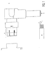
- Figure 1 shows a schematic view of a preferred embodiment of the present invention.
- Figure 2 shows a side view of the preferred embodiment.
- Figure 3 shows a side view of the preferred embodiment on a larger scale.
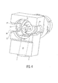
- Figure 4 shows a perspective view of the cap of the preferred embodiment.
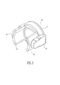
- Figure 5 shows a perspective view of the cap of the preferred embodiment.
- Referring to the accompanying drawings, Figure 1 shows a preferred embodiment of the present invention wherein cable termination is at a 90 degree angle from a mating connector. Other embodiments, it should be noted, may be adaptable to any other angles of termination from 0-180 degrees, e.g. 45 degrees, 135 degrees, in line or parallel termination, etc. Area a is the mating area for a mating connector, such as that shown at m. Area b is where a coax cable, such as that shown at w, is inserted. Coax cable w consists here of outer conductor o, inner conductor i and dielectric e. The outer conductor o and inner conductor i of cable w will interface with the embodiment to provide an electrical contact, as will be described further below. Area c provides access for crimping and/or soldering of inner conductor i inserted in b, as will be explained in further detail below. Thus, when wire w is soldered within area c and area a mated with an appropriate mating connector m, connection is made for conduction through the connector.
-
- Components of the embodiment of Figure 1 are shown in Figure 2.
Connector housing 30 comprisesouter contact 31, configured for mating with a corresponding contact of a mating connector; dielectric 32 providing insulation between the outer contact and core member; retainingring 33 providing security for retention of the dielectric; and external connector housing 34 which may be configured as desired, for example to mate with an external housing as is further described below. - External connector housing 34, as was mentioned above, may be adapted for installation of an external housing (not shown) that is configured to mate with specific housings. For example, FAKRA keyed connections are known in the art and so an external FAKRA housing may be employed over housing 34 to mate with a corresponding FAKRA connector.
-
Outer contact 31, dielectric 32,retaining ring 33 and external connector housing 34 are made of materials as known in the art. For example,outer contact 31 may be stamped or formed, dielectric 32 may be screw machine or molded, retainingring 33 may be screw machine or drawn and external connector housing 34 may be screw machine or die cast. - The specific shape of a connector housing of any particular embodiment of the present invention is determined by the mating connector with which it is to interact. In the preferred embodiments, these, along with any external housing, are standardized shapes and/or configurations. It should be noted that embodiments may be used, as well, for PCB connection.
-
Cable housing 20, comprised here ofexternal cable housing 21 surrounding abore 23 and further having depending therefromouter conductor surface 24 andferrule 25, is connected at a 90 degree angle in this embodiment toconnector housing 30. In other embodiments,cable housing 20 andconnector housing 30 may be connected at any, desired predetermined degree angle from 0-180 degrees, e.g., 45 degrees, 135 degrees, in line or parallel termination, thus providing a connector adaptable for a variety of cable orientations. Each of these components is made from materials as known in the art. These and other components may be plated as well and, turning briefly to Figure 3, recess 26 as well asbores - Returning to Figure 2, the outer conductor o of a coaxial cable (shown as w) is mounted between
outer conductor surface 24 andmating ferrule 25. Cable dielectric e passes into interior bore 23 and terminates. Inner conductor i of cable w passes throughinterior bore 23 and intobore 13 ofcore member 50, where it will be crimped and/or soldered as will be further described below. - Figure 3 shows
core member 50 extending withincable housing 20 andconnector housing 30, and further extending at least partially into openended recess 26, whereby it may be accessed in order to permit crimping and/or soldering of a cable inner conductor, as is described further herein. - Turning now to Figure 4, a rear view of the embodiment of Figures 1 and 2 is seen. Open ended
recess 26 is shown.Port 27 is a circular opening withinexternal cable housing 21.Cutouts recess 26 and located on opposite sides ofexternal cable housing 21. When an inner conductor is passed throughbore 23 and, in turn, throughbore 13, thencutouts recess 26, depending upon the installation means required. For example, in embodiments wherein only soldered connections are made, there may be no cutouts used. - In the preferred embodiment, soldering of the inner conductor to the core member may occur through pre-tinning the inner conductor, feeding the inner conductor into
bore 13 and heating thecore member 50 to melt the solder, and thereby establish a connection. - Use of
bore 13 is especially advantageous for either or both soldering and crimping installation, as it provides a closed guide means for the inner conductor to be fed withincore member 50. A closed guide means disposed within a core member, such asbore 13, is used in the preferred embodiments of the present invention, to assist in guiding the inner conductor. - Figure 5 shows the
cap member 40 of the preferred embodiment of Figure 1.Cap member 40 is formed to be disposed into open endedrecess 26 ofexternal cable housing 21 to provide a cover foraccess port 27 andcutouts core member 50. In this particular embodiment,cap member 40 is comprised ofcover 41,flanges mating flanges flanges flange 48 mating withcutout 28 andflange 49 mating withcutout 29. Thus, the cap is press fit upon the remaining assembly. It should be noted that the configuration of a cap member and installation thereof, in any given embodiment, is dependent upon the configuration of the open ended recess in that embodiment, so that the two are in complimentary mating configuration. It should also be noted that, by use of an unitary cap member in this and other embodiments, a single means is provided for sealing the access area, thus simplifying assembly. - It should be noted that other embodiments may utilize cable to cable connection, for example, where a connector housing component is configured to mate with the appropriate connector on a cable, as well as cable - PCB connection, for example, where a connector housing component is configured to mate with the appropriate connector on a PCB. Therefore, the term "connector housing," as used herein, is intended to include those embodiments that are configured to connect to a cable as well as those configured to connect to a printed circuit board and, similarly, the term "mating connector" is intended to include cable and printed circuit board connectors.
Claims (11)
- A coaxial cable connector comprising:a connector housing (30) for interfacing with a mating connector,a cable housing (20) connected to said connector housing and having an open ended recess (26),a core member (50) having guide means (13), said core member extending within said connector housing and said cable housing and at least partially into said open ended recess (26) so that said guide means is accessible through said open ended recess for receiving a coax cable inner conductor (i), anda cap (40) for sealing said open ended recess upon installation of said inner conductor of said coax cable.
- A connector as in claim 1, wherein said connector housing (30) comprises an outer contact (31) configured for mating with a corresponding contact of a mating connector, a dielectric (32) for insulating said outer contact from said core member (50) and an external connector housing (34).
- A connector as in claim 2, wherein said external connector housing (34) is adapted for installation of an external housing.
- A connector as in claim 1, 2 or 3, wherein said cable housing (20) includes an external cable housing (21) surrounding a bore (23) with an outer conductor surface (24) and ferrule (25) depending from said external cable housing.
- A connector as in any preceding claim, wherein at least one opening or cutout (28,29) bounds said open ended recess (26) of said cable housing.
- A connector as in any preceding claim, wherein said cap (40) is in mating configuration with said open ended recess (26).
- A connector as in any preceding claim, wherein said cap (40) is unitary.
- A connector as in any preceding claim, wherein said connector housing (30) is connected to said cable housing (20) at a predetermined angle, for example, at a predetermined angle from 0 - 180 degrees.
- A method for installing a coaxial cable connector with a mating connector and coax cable, comprising:interfacing a connector housing (30) with said mating connector,introducing said cable (w) into a cable housing (20), whereby said cable housing is connected to said connector housing, said cable housing having an open ended recess (26),installing a core member (50) to an inner conductor of said coax cable, said core member having disposed therein a closed guide means (13), and said core member extending within said connector housing and said cable housing and at least partially into said open ended recess so that said closed guide means is accessible through said open ended recess for receiving said inner conductor, andsealing said open ended recess (26) upon installation of said inner conductor of said coax cable.
- A method as in claim 9, wherein said installing occurs by soldering or crimping.
- A connection created accorded to the method of claim 9 or 10.
Applications Claiming Priority (2)
| Application Number | Priority Date | Filing Date | Title |
|---|---|---|---|
| US10/056,700 US6676445B2 (en) | 2002-01-25 | 2002-01-25 | Coaxial cable connector apparatus, methods and articles of manufacture for angle or in-line applications |
| US56700 | 2002-01-25 |
Publications (3)
| Publication Number | Publication Date |
|---|---|
| EP1331702A2 true EP1331702A2 (en) | 2003-07-30 |
| EP1331702A3 EP1331702A3 (en) | 2004-06-09 |
| EP1331702B1 EP1331702B1 (en) | 2008-08-20 |
Family
ID=22006071
Family Applications (1)
| Application Number | Title | Priority Date | Filing Date |
|---|---|---|---|
| EP03250438A Expired - Lifetime EP1331702B1 (en) | 2002-01-25 | 2003-01-24 | Coaxial cable connector |
Country Status (8)
| Country | Link |
|---|---|
| US (1) | US6676445B2 (en) |
| EP (1) | EP1331702B1 (en) |
| JP (1) | JP4342188B2 (en) |
| KR (1) | KR100906076B1 (en) |
| BR (1) | BR0300360A (en) |
| CA (1) | CA2417065C (en) |
| DE (1) | DE60322987D1 (en) |
| ES (1) | ES2312724T3 (en) |
Cited By (1)
| Publication number | Priority date | Publication date | Assignee | Title |
|---|---|---|---|---|
| EP1811613A1 (en) * | 2006-01-24 | 2007-07-25 | Hirschmann Car Communication GmbH | Connector, in particular Fakra standard angled-connector for vehicle applications. |
Families Citing this family (30)
| Publication number | Priority date | Publication date | Assignee | Title |
|---|---|---|---|---|
| JP4076157B2 (en) * | 2003-07-30 | 2008-04-16 | ヒロセ電機株式会社 | Coaxial electrical connector |
| JP4498721B2 (en) * | 2003-11-05 | 2010-07-07 | 株式会社オートネットワーク技術研究所 | Connector manufacturing method |
| US20070014277A1 (en) * | 2005-07-14 | 2007-01-18 | Yahoo! Inc. | Content router repository |
| US7223131B2 (en) * | 2005-09-02 | 2007-05-29 | Tyco Electronics Corporation | Three position electrical connector assembly |
| US7347742B2 (en) * | 2005-09-02 | 2008-03-25 | Tyco Electronics Corporation | Connector assembly including provision for body clip |
| US7285011B2 (en) * | 2005-10-24 | 2007-10-23 | Tyco Electronics Corporation | Cable exit for an electrical connector assembly |
| US7273394B1 (en) * | 2005-11-17 | 2007-09-25 | Yazaki North America, Inc. | Right angle coaxial connector |
| US20070257160A1 (en) * | 2006-05-08 | 2007-11-08 | M/A-Com, Inc. | Cable attaching clamp |
| JP2008098125A (en) * | 2006-10-12 | 2008-04-24 | Shintake Sangyo Kk | L-shaped plug and its manufacturing method |
| US7347745B1 (en) | 2007-01-19 | 2008-03-25 | Tyco Electronics Corporation | Three position electrical connector assembly |
| US7494374B2 (en) | 2007-02-01 | 2009-02-24 | Tyco Electronics Corporation | Panel mount electrical connector |
| US7326063B1 (en) | 2007-02-06 | 2008-02-05 | Tyco Electronics Corporation | Panel mount connector housing |
| US7682205B2 (en) * | 2007-11-15 | 2010-03-23 | Tyco Electronics Corporation | Multi position electrical connector assembly |
| DE202007017309U1 (en) * | 2007-12-12 | 2008-02-28 | Rosenberger Hochfrequenztechnik Gmbh & Co. Kg | coaxial |
| US7909645B2 (en) * | 2008-06-24 | 2011-03-22 | Tyco Electronics Corporation | Coaxial cable connector housing |
| JP5067980B2 (en) * | 2010-10-06 | 2012-11-07 | 日本航空電子工業株式会社 | Coaxial connector |
| US8668504B2 (en) | 2011-07-05 | 2014-03-11 | Dave Smith Chevrolet Oldsmobile Pontiac Cadillac, Inc. | Threadless light bulb socket |
| US8641447B2 (en) * | 2011-12-20 | 2014-02-04 | Tyco Electronics Corporation | Coaxial connector |
| WO2014068571A1 (en) * | 2012-10-31 | 2014-05-08 | Galtronics Corporation Ltd. | Wideband whip antenna |
| US10069187B2 (en) | 2013-03-21 | 2018-09-04 | Nec Corporation | Microwave outdoor radio device |
| DE202013006067U1 (en) * | 2013-07-05 | 2013-08-12 | Rosenberger Hochfrequenztechnik Gmbh & Co. Kg | Connectors |
| US9478929B2 (en) | 2014-06-23 | 2016-10-25 | Ken Smith | Light bulb receptacles and light bulb sockets |
| US9614302B2 (en) * | 2015-02-04 | 2017-04-04 | Commscope Technologies Llc | Right angle coaxial cable and connector assembly |
| US9461383B1 (en) | 2015-09-28 | 2016-10-04 | Amphenol Corporation | High signal isolation electrical connector |
| US9762001B2 (en) | 2016-02-01 | 2017-09-12 | Delphi Technologies, Inc. | Right angled coaxial electrical connector and methods for verifying proper assembly thereof |
| CN107394542A (en) * | 2017-08-30 | 2017-11-24 | 陕西益华电气股份有限公司 | A kind of bent type radio frequency coaxial connector of connecting cable |
| CN108199167B (en) * | 2018-04-04 | 2024-02-09 | 东莞市信翰精密工业有限公司 | Radio frequency coaxial connector with small plugging force |
| USD884641S1 (en) * | 2018-09-27 | 2020-05-19 | Viablue Gmbh | Shells for connectors and plugs for audio and videocables |
| US12308594B2 (en) | 2021-09-14 | 2025-05-20 | Intel Corporation | Ultra-low profile coaxial cable connector |
| CN115810947B (en) * | 2023-01-31 | 2023-05-02 | 深圳市西点精工技术有限公司 | FAKRA connector |
Citations (2)
| Publication number | Priority date | Publication date | Assignee | Title |
|---|---|---|---|---|
| EP0090538A2 (en) | 1982-03-31 | 1983-10-05 | AMP INCORPORATED (a New Jersey corporation) | Right angle coaxial connector |
| DE19854503C1 (en) | 1998-11-25 | 2001-05-10 | Tyco Electronics Logistics Ag | Coaxial cable angle connector plug for HF line has connector housing provided with front plug part and rear opening fitted with cover providing access for formation of soldered connections |
Family Cites Families (10)
| Publication number | Priority date | Publication date | Assignee | Title |
|---|---|---|---|---|
| BE416412A (en) * | 1935-07-08 | |||
| US2238834A (en) * | 1940-05-16 | 1941-04-15 | Richard Di Pippo | Electric connector plug |
| US3047828A (en) * | 1960-06-16 | 1962-07-31 | Alvero C Gregson | Connector |
| US3480722A (en) * | 1967-10-09 | 1969-11-25 | United Carr Inc | Coaxial cable connector |
| US4655534A (en) * | 1985-03-15 | 1987-04-07 | E. F. Johnson Company | Right angle coaxial connector |
| US4881912A (en) * | 1988-04-29 | 1989-11-21 | Specialty Connector Company, Inc. | High voltage coaxial connector |
| US4932898A (en) * | 1989-02-07 | 1990-06-12 | Itt Corporation | Termination system for coaxial conductor |
| US5316499A (en) * | 1993-01-21 | 1994-05-31 | Dynawave Incorporated | Coaxial connector with rotatable mounting flange |
| US6450829B1 (en) | 2000-12-15 | 2002-09-17 | Tyco Electronics Canada, Ltd. | Snap-on plug coaxial connector |
| US6361348B1 (en) | 2001-01-15 | 2002-03-26 | Tyco Electronics Corporation | Right angle, snap on coaxial electrical connector |
-
2002
- 2002-01-25 US US10/056,700 patent/US6676445B2/en not_active Expired - Fee Related
-
2003
- 2003-01-24 BR BR0300360-4A patent/BR0300360A/en not_active IP Right Cessation
- 2003-01-24 DE DE60322987T patent/DE60322987D1/en not_active Expired - Lifetime
- 2003-01-24 KR KR1020030004854A patent/KR100906076B1/en not_active Expired - Fee Related
- 2003-01-24 CA CA2417065A patent/CA2417065C/en not_active Expired - Fee Related
- 2003-01-24 ES ES03250438T patent/ES2312724T3/en not_active Expired - Lifetime
- 2003-01-24 EP EP03250438A patent/EP1331702B1/en not_active Expired - Lifetime
- 2003-01-27 JP JP2003016846A patent/JP4342188B2/en not_active Expired - Fee Related
Patent Citations (2)
| Publication number | Priority date | Publication date | Assignee | Title |
|---|---|---|---|---|
| EP0090538A2 (en) | 1982-03-31 | 1983-10-05 | AMP INCORPORATED (a New Jersey corporation) | Right angle coaxial connector |
| DE19854503C1 (en) | 1998-11-25 | 2001-05-10 | Tyco Electronics Logistics Ag | Coaxial cable angle connector plug for HF line has connector housing provided with front plug part and rear opening fitted with cover providing access for formation of soldered connections |
Cited By (1)
| Publication number | Priority date | Publication date | Assignee | Title |
|---|---|---|---|---|
| EP1811613A1 (en) * | 2006-01-24 | 2007-07-25 | Hirschmann Car Communication GmbH | Connector, in particular Fakra standard angled-connector for vehicle applications. |
Also Published As
| Publication number | Publication date |
|---|---|
| CA2417065C (en) | 2010-03-30 |
| KR100906076B1 (en) | 2009-07-02 |
| ES2312724T3 (en) | 2009-03-01 |
| KR20030064336A (en) | 2003-07-31 |
| CA2417065A1 (en) | 2003-07-25 |
| JP4342188B2 (en) | 2009-10-14 |
| US20030143893A1 (en) | 2003-07-31 |
| DE60322987D1 (en) | 2008-10-02 |
| EP1331702B1 (en) | 2008-08-20 |
| JP2003217755A (en) | 2003-07-31 |
| US6676445B2 (en) | 2004-01-13 |
| EP1331702A3 (en) | 2004-06-09 |
| BR0300360A (en) | 2003-09-09 |
Similar Documents
| Publication | Publication Date | Title |
|---|---|---|
| EP1331702B1 (en) | Coaxial cable connector | |
| EP1766728B1 (en) | Modular plug assemblies, terminated cable assemblies and methods for forming the same | |
| US4493525A (en) | Electrical plug connector and receptacle therefor | |
| US4611878A (en) | Electrical plug connector | |
| KR101703461B1 (en) | Header assembly | |
| US5046952A (en) | Right angle connector for mounting to printed circuit board | |
| US6893291B2 (en) | Coaxial plug connector having a longitudinally divided shield housing, and coaxial angled plug connector | |
| US6309255B1 (en) | Electrical connector having power contacts for providing high electrical power | |
| US6106338A (en) | Cable end receptacle connector having a device preventing excess molten material from flowing into the connector | |
| US20080026612A1 (en) | Multiposition RF connector | |
| JP4729307B2 (en) | Circuit board connector having an integral dielectric cover | |
| US20070249192A1 (en) | Earthing structure and electrical connector using the same | |
| US8062054B2 (en) | Cable connector assembly with improved structure strength thereof | |
| US10505309B2 (en) | Electrical device having a seal assembly | |
| US6030240A (en) | Coaxial connectors | |
| US9692168B1 (en) | Header assembly | |
| US20240396256A1 (en) | Single-pair ethernet mount housing | |
| CN101630781A (en) | Coaxial cable connector housing | |
| US6699074B1 (en) | Cable connector assembly having improved grounding means | |
| US7014480B1 (en) | Grounding methods and apparatus for connector assemblies | |
| GB2307113A (en) | Coaxial connector | |
| US6200163B1 (en) | Electrical connector including means for terminating the shield of a high speed cable | |
| JP2024081319A (en) | Electrical Connectors | |
| US7841882B2 (en) | Micro gangmate multi-port modular RF card edge connector | |
| US7153156B1 (en) | Coaxial cable connector |
Legal Events
| Date | Code | Title | Description |
|---|---|---|---|
| PUAI | Public reference made under article 153(3) epc to a published international application that has entered the european phase |
Free format text: ORIGINAL CODE: 0009012 |
|
| AK | Designated contracting states |
Designated state(s): AT BE BG CH CY CZ DE DK EE ES FI FR GB GR HU IE IT LI LU MC NL PT SE SI SK TR |
|
| AX | Request for extension of the european patent |
Extension state: AL LT LV MK RO |
|
| PUAL | Search report despatched |
Free format text: ORIGINAL CODE: 0009013 |
|
| AK | Designated contracting states |
Kind code of ref document: A3 Designated state(s): AT BE BG CH CY CZ DE DK EE ES FI FR GB GR HU IE IT LI LU MC NL PT SE SI SK TR |
|
| AX | Request for extension of the european patent |
Extension state: AL LT LV MK RO |
|
| 17P | Request for examination filed |
Effective date: 20041119 |
|
| AKX | Designation fees paid |
Designated state(s): DE ES FR GB IT |
|
| 17Q | First examination report despatched |
Effective date: 20050314 |
|
| 17Q | First examination report despatched |
Effective date: 20050314 |
|
| GRAP | Despatch of communication of intention to grant a patent |
Free format text: ORIGINAL CODE: EPIDOSNIGR1 |
|
| GRAS | Grant fee paid |
Free format text: ORIGINAL CODE: EPIDOSNIGR3 |
|
| GRAA | (expected) grant |
Free format text: ORIGINAL CODE: 0009210 |
|
| AK | Designated contracting states |
Kind code of ref document: B1 Designated state(s): DE ES FR GB IT |
|
| REG | Reference to a national code |
Ref country code: GB Ref legal event code: FG4D |
|
| REF | Corresponds to: |
Ref document number: 60322987 Country of ref document: DE Date of ref document: 20081002 Kind code of ref document: P |
|
| REG | Reference to a national code |
Ref country code: ES Ref legal event code: FG2A Ref document number: 2312724 Country of ref document: ES Kind code of ref document: T3 |
|
| PLBE | No opposition filed within time limit |
Free format text: ORIGINAL CODE: 0009261 |
|
| STAA | Information on the status of an ep patent application or granted ep patent |
Free format text: STATUS: NO OPPOSITION FILED WITHIN TIME LIMIT |
|
| 26N | No opposition filed |
Effective date: 20090525 |
|
| PGFP | Annual fee paid to national office [announced via postgrant information from national office to epo] |
Ref country code: ES Payment date: 20100126 Year of fee payment: 8 |
|
| PGFP | Annual fee paid to national office [announced via postgrant information from national office to epo] |
Ref country code: FR Payment date: 20100205 Year of fee payment: 8 Ref country code: IT Payment date: 20100126 Year of fee payment: 8 |
|
| PGFP | Annual fee paid to national office [announced via postgrant information from national office to epo] |
Ref country code: DE Payment date: 20100127 Year of fee payment: 8 Ref country code: GB Payment date: 20100125 Year of fee payment: 8 |
|
| GBPC | Gb: european patent ceased through non-payment of renewal fee |
Effective date: 20110124 |
|
| REG | Reference to a national code |
Ref country code: FR Ref legal event code: ST Effective date: 20110930 |
|
| PG25 | Lapsed in a contracting state [announced via postgrant information from national office to epo] |
Ref country code: FR Free format text: LAPSE BECAUSE OF NON-PAYMENT OF DUE FEES Effective date: 20110131 |
|
| PG25 | Lapsed in a contracting state [announced via postgrant information from national office to epo] |
Ref country code: GB Free format text: LAPSE BECAUSE OF NON-PAYMENT OF DUE FEES Effective date: 20110124 |
|
| PG25 | Lapsed in a contracting state [announced via postgrant information from national office to epo] |
Ref country code: IT Free format text: LAPSE BECAUSE OF NON-PAYMENT OF DUE FEES Effective date: 20110124 |
|
| REG | Reference to a national code |
Ref country code: DE Ref legal event code: R119 Ref document number: 60322987 Country of ref document: DE Effective date: 20110802 |
|
| REG | Reference to a national code |
Ref country code: ES Ref legal event code: FD2A Effective date: 20120305 |
|
| PG25 | Lapsed in a contracting state [announced via postgrant information from national office to epo] |
Ref country code: ES Free format text: LAPSE BECAUSE OF NON-PAYMENT OF DUE FEES Effective date: 20110125 |
|
| PG25 | Lapsed in a contracting state [announced via postgrant information from national office to epo] |
Ref country code: DE Free format text: LAPSE BECAUSE OF NON-PAYMENT OF DUE FEES Effective date: 20110802 |