EP1331595A2 - Connector device for cards permitting insertion of different types of cards - Google Patents
Connector device for cards permitting insertion of different types of cards Download PDFInfo
- Publication number
- EP1331595A2 EP1331595A2 EP03001189A EP03001189A EP1331595A2 EP 1331595 A2 EP1331595 A2 EP 1331595A2 EP 03001189 A EP03001189 A EP 03001189A EP 03001189 A EP03001189 A EP 03001189A EP 1331595 A2 EP1331595 A2 EP 1331595A2
- Authority
- EP
- European Patent Office
- Prior art keywords
- card
- contact
- connector terminals
- accommodating section
- pressing member
- Prior art date
- Legal status (The legal status is an assumption and is not a legal conclusion. Google has not performed a legal analysis and makes no representation as to the accuracy of the status listed.)
- Granted
Links
Images






Classifications
-
- H—ELECTRICITY
- H01—ELECTRIC ELEMENTS
- H01R—ELECTRICALLY-CONDUCTIVE CONNECTIONS; STRUCTURAL ASSOCIATIONS OF A PLURALITY OF MUTUALLY-INSULATED ELECTRICAL CONNECTING ELEMENTS; COUPLING DEVICES; CURRENT COLLECTORS
- H01R13/00—Details of coupling devices of the kinds covered by groups H01R12/70 or H01R24/00 - H01R33/00
- H01R13/64—Means for preventing incorrect coupling
- H01R13/642—Means for preventing incorrect coupling by position or shape of contact members
-
- G—PHYSICS
- G06—COMPUTING OR CALCULATING; COUNTING
- G06K—GRAPHICAL DATA READING; PRESENTATION OF DATA; RECORD CARRIERS; HANDLING RECORD CARRIERS
- G06K7/00—Methods or arrangements for sensing record carriers, e.g. for reading patterns
- G06K7/0013—Methods or arrangements for sensing record carriers, e.g. for reading patterns by galvanic contacts, e.g. card connectors for ISO-7816 compliant smart cards or memory cards, e.g. SD card readers
- G06K7/0021—Methods or arrangements for sensing record carriers, e.g. for reading patterns by galvanic contacts, e.g. card connectors for ISO-7816 compliant smart cards or memory cards, e.g. SD card readers for reading/sensing record carriers having surface contacts
- G06K7/003—Methods or arrangements for sensing record carriers, e.g. for reading patterns by galvanic contacts, e.g. card connectors for ISO-7816 compliant smart cards or memory cards, e.g. SD card readers for reading/sensing record carriers having surface contacts means for pressing the connector contacts in the direction of the card contacts to assure trustworthy electrical connection between card and connector
-
- G—PHYSICS
- G06—COMPUTING OR CALCULATING; COUNTING
- G06K—GRAPHICAL DATA READING; PRESENTATION OF DATA; RECORD CARRIERS; HANDLING RECORD CARRIERS
- G06K7/00—Methods or arrangements for sensing record carriers, e.g. for reading patterns
- G06K7/0013—Methods or arrangements for sensing record carriers, e.g. for reading patterns by galvanic contacts, e.g. card connectors for ISO-7816 compliant smart cards or memory cards, e.g. SD card readers
- G06K7/0021—Methods or arrangements for sensing record carriers, e.g. for reading patterns by galvanic contacts, e.g. card connectors for ISO-7816 compliant smart cards or memory cards, e.g. SD card readers for reading/sensing record carriers having surface contacts
Definitions
- the present invention relates to the structure of a connector device for use with small memory cards employed in portable information terminals including mobile telephones and laptop personal computers (PCs) and memory-matched devices including digital cameras and digital audiovisual (AV) devices.
- portable information terminals including mobile telephones and laptop personal computers (PCs)
- memory-matched devices including digital cameras and digital audiovisual (AV) devices.
- AV digital audiovisual
- Connector devices for cards are generally used as expanded recording devices for electronic apparatuses including PCs and digital cameras.
- a connector device for cards can only match one type of memory card with the result that only one specific type of memory card can be inserted into one connector device for cards. For this reason, if many different types of memory cards are to be used, different connector devices for cards, each dedicated to only one type of memory cards, have to be made ready.
- an object of the present invention is to solve the problems noted above and provide a connector device for cards in which connector terminals are arranged in tandem in the inserting direction of cards to enable cards different in length to be inserted and cards to be inserted smoothly.
- first means is characterized in that it is provided with a housing having an accommodating section permitting insertion of both a short and thin first card and a second card longer and thicker than the first card, a plurality of first connector terminals to be connected to the contact terminal section of the first card, and a plurality of second connector terminals to be connected to the contact terminal section of the second card, the first and second connector terminals being respectively arranged towards an inlet and towards a deep end in a card inserting direction in the accommodating section, wherein the first connector terminals are made up of elastic pieces each having a contact supported on one end side by a bottom of the accommodating section in a cantilever way and protruding into the accommodating section on another end side; the accommodating section is provided with a pressing member to suppress the first connector terminals to press down the contacts towards the bottom of the accommodating section; when the first card is inserted, the pressing member is not displaced but the contacts of the first connector terminals and the contact terminal section of the first card come into contact with each
- Second means is characterized in that the housing is provided with a card insertion slot arranged in a front face of the housing and guides arranged on two sides of the card insertion slot to guide the first and second cards into the accommodating section, wherein a first guide face to guide, in contact with a flank of the first card, insertion of the first card and a second guide face to guide, in contact with a flank of the second card, insertion of the second card are formed on each of the guides; and the second guide face is formed in a position lower than the first guide face so that the bottom face of the second card to be inserted into the accommodating section is positioned lower than a bottom face of the first card to be inserted into the accommodating section.
- Third means according to the invention is characterized in that the pressing member is provided with a suppressor displaceable in a vertical direction to suppress the first connector terminals and a driver to displace downwards the suppressor by its contact with the bottom face of the second card, wherein the driver is arranged in a position higher than the bottom face of the second card to be inserted into the accommodating section and lower than the bottom face of the first card to be inserted into the accommodating section.
- Fourth means according to the invention is characterized in that one end part of the pressing member, which is a part closer to the inlet, is rotatably borne by the accommodating section in the card inserting direction in the accommodating section; the suppressor is formed on the deep end of the pressing member in the card inserting direction; and the suppressor is held in a state of being energized upwards by elasticity of the first connector terminals.
- the first connector terminals are arranged closer to the inlet in the card inserting direction in the accommodating section than the second connector terminals, one end side of each being made up of an elastic piece supported in a cantilever way by an under side of the accommodating section into which the first card and the second card are to be inserted;
- the pressing member is provided with a suppressor displaceable in the vertical direction to suppress the first connector terminals and a driver to displace downwards the suppressor by its contact with the bottom face of the second card;
- the driver is formed protruding higher than a position of the bottom face of the second card to be inserted into the accommodating section; and when the first card is inserted, the driver is accommodated into a contact terminal section forming concave formed on a forward edge on an inserting side of the first card.
- Sixth means according to the invention is characterized in that the first connector terminals, pivoting on a closer-to-the-inlet side in the card inserting direction, are extended deeper inside in a cantilever way; towards a tip of each is formed the contact to come into contact with the contact terminal section of the first card; the pressing member, pivoting for its rotation on the deep end in the card inserting direction, has towards its tip the suppressor to press the tips of the first connector terminals; and the driver is formed protruding in the vicinity of the suppressor in a direction opposite the suppressor.
- Seventh means according to the invention is characterized in that a guide member to guide the second card to a position in which it comes into contact with the driver is arranged on the closer-to-the-inlet side of the pressing member in the card inserting direction.
- Eighth means according to the invention is characterized in that the suppressor is energized upwards by the elasticity of the first connector terminals; the guide member is extended, pivoting for its rotation on a deeper side in the card inserting direction; and its tip is engaged with an upper face of the suppressor.
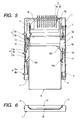
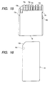
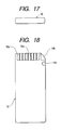
- Fig. 1 is a plan of a connector device for cards; Fig. 2, a front view of the same; Fig. 3, a vertical section of the same; Fig. 4, a vertical section of the same in another position; Fig. 5, a plan of the connector device for cards when a first card is inserted; Fig. 6, a front view of the same; Fig. 7, a vertical section of the same; Fig. 8, a vertical section of the same in another position; Fig. 9, a plan of the connector device for cards when a second card is inserted; Fig. 10, a front view of the same; Fig. 11, a vertical section of the same; Fig.
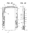
- FIG. 19 through Fig. 24 illustrate another preferred embodiment of the invention, wherein Fig. 19 shows a plan of the connector device for cards; Fig. 20, a vertical section of the same; Fig. 21, a plan of the connector device for cards when the first card is inserted; Fig. 22, a vertical section of the same; Fig. 23, a plan of the connector device for cards when the second card is inserted; and Fig. 24, a vertical section of the same.
- a housing 1 is formed of an insulating material such as synthetic resin in a rectangular box shape with its front and top being open. At the center of this housing 1 is arranged an accommodating section 1a, and in the housing 1 is also formed a card insertion slot 1b continuous from the accommodating section 1a and extending to the front face of the housing 1.
- each of first and second connector terminals 2 and 3 in a plurality made up of an elastic electroconductive metallic material.
- the first connector terminals 2 are arranged in the accommodating section 1a in closer positions to the inlet in the card inserting direction, each formed of a planar base, a connecting piece 2a formed in a substantially Z shape by being bent in mutually opposite directions from this base, and a contact piece 2b.
- Each of the first connector terminals 2 is arranged with its connecting piece 2a, formed at one end of it, being exposed outward through an opening 1c provided in the bottom face of the accommodating section 1a, and the soldering of this connecting piece 2a to a circuit pattern on an external circuit board such as that of an electronic device enables signals to be transmitted.
- the contact piece 2b formed towards the other end of the base of each of the first connector terminals 2, is supported by the bottom of the accommodating section 1a in a cantilever way and arranged protruding into the accommodating section 1a.
- a contact 2c At the tip of the contact piece 2b is formed a contact 2c to be connected to contact terminal sections 15a of a first card 15 to be described later.
- the second connector terminals 3 are arranged deeper than the positions in which the first connector terminals 2 of the accommodating section 1a are arranged, each formed of a planar base, a connecting piece 3a bent in mutually opposite directions from this base, and a contact piece 3b.
- Each of the second connector terminals 3 is arranged with its connecting piece 3a, formed at one end of it, being exposed outward through an outer backward side of the housing 1, and the soldering of this connecting piece 3a to a circuit pattern on an external circuit board such as that of an electronic device enables signals to be transmitted.
- the contact piece 3b formed extending towards the other end of the base of each of the second connector terminals 3, is arranged protruding into the accommodating section 1a. At the tip of the contact piece 3b is formed a contact 3c to be connected to the contact terminal section 16a of a second card 16 to be described later.
- the card insertion slot 1b is provided with a flat part 1d made up of a plane to guide the flat part of the second card 16 to be described later, and on two sides between which this flat part 1d is held are formed a pair of guides 1e and 1e to guide the flanks of the first and second card 15 and 16 to be described later.
- the card insertion slot 1b is so formed that its maximum width is substantially equal to the width of the first card 15 and its maximum thickness is substantially equal to the thickness of the second card 16.
- each guide 1e and 1e On the pair of guides 1e and 1e are formed a plurality of guide faces made up of stepwise parallel faces, and towards the upper end of each guide 1e is formed a concave first guide face 1f to guide the first card 15 to its inserted position while keeping in contact with the flank of the first card 15. Toward the lower end of each guide 1e is formed, positioned farther inside than the concave first guide face 1f, a convex second guide face 1g to guide the second card 16 to its inserted position while keeping in contact with the flank of the second card 16.
- first guide face 1f and the second guide face 1g are so formed that the first guide face 1f is located farther outside than the second guide face 1g and the second guide face 1g is situated in a lower position than the first guide face 1f, thus the two guide faces being formed in different positions in the direction of height.
- the formation in this manner of the second guide face 1g in a lower position than the first guide face 1f and the formation of the bottom face of the second card 16 to be described later to be inserted into the accommodating section 1a in a lower position than the bottom face of the first card 15 to be described later to be inserted into the accommodating section 1a make it possible, by such a simple configuration that the first and second guide faces 1f and 1g to guide different types of card are formed in positions differing in the direction of height, for the contacts 2c of the first connector terminals 2 to be pressed down into a position where they will not come into contact with the bottom face of the second card 16 only when the second card 16 is inserted.
- a spring accommodating part On one flank of the housing 1 is formed a spring accommodating part to accommodate a return spring 4 made up of a coil spring to energize a sliding member 9 to be described later in the direction of ejecting a card.
- a lock pin 5 Towards one end opposite this spring accommodating part is rotatably borne a lock pin 5, made up of a metal wire, to hold the sliding member 9 in the inserted position of the card.
- a fixed contact member 6 which is part of a detecting means, and a first movable contact member 7 and a second movable contact member 8 in upper and lower positions with this fixed contact member 6 between them.
- the fixed contact member 6 is made up of an electroconductive metal plate, and on both sides of its central base are formed planar the first contact piece 6a and second contact piece 6b opposite each other and extending in vertical directions. These the first contact piece 6a and second contact piece 6b extended from the base in a state twisted relative to each other by 90 degrees, and the contacts on their respective end sides are provided in mutually crossing directions.
- On the base is formed a terminal piece 6c protruding outward from an outer side of the housing 1.
- the first movable contact member 7 is also made up of an electroconductive metal plate, and on it are formed a planar movable piece 7a extending from the base towards one downward end and a terminal piece 7b extending in a direction crossing the movable piece 7a and protruding outward from an outer side of the housing 1.
- the free end side of the movable piece 7a is bent downward in a substantially U shape, and its tip constitutes the contact to go into and out of contact with the contact of the first contact piece 6a of the fixed contact member 6.
- the first contact piece 6a of the fixed contact member 6 and the movable piece 7a of the first movable contact member 7 are arranged in the housing 1 in a state of being opposite each other in the vertical direction (in this case, the direction orthogonal to the card inserting direction) , and the movable piece 7a and the first contact piece 6a are formed to be displaced in the vertical direction by the pressing of the upper face of the bent part of the movable piece 7a against a rotating member 12 of the operating section to be described later.
- the completion of the insertion of the first card 15 to be described later can be detected.
- the second movable contact member 8 is also made up of an electroconductive metal plate, and on it are formed a planar movable piece 8a extending from the base towards one upward end and a terminal piece 8b extending in a direction crossing the movable piece 8a and protruding outward from an outer side of the housing 1.
- the free end side of the movable piece 8a is bent in a substantially S shape having inflating parts inflating in mutually opposite directions, and one of these inflating parts constitutes the contact to go into and out of contact with the contact of the second contact piece 6b of the fixed contact member 6.
- the second contact piece 6b of the fixed contact member 6 and the movable piece 8a of the second movable contact member 8 are arranged in the housing 1 in a state of being opposite each other in the horizontal direction, and the movable piece 8a and the second contact piece 6b are formed to be displaced in the horizontal direction by the pressing of the other inflated part of the movable piece 8a against an identifier 15d of the first card 15 to be described later.
- the coming into contact of the second contact piece 6b of the fixed contact member 6 and the movable piece 8a of the second movable contact member 8 with each other whether or not writing into the first card 15 is forbidden, to be described later, can be detected.
- the detecting means is formed of the first movable contact member 7, the fixed contact member 6 of which one end side comes into and out of contact with this first movable contact member 7 and the second movable contact member 8 of which the other end side comes into and out of contact with fixed contact member 6, the completion of the insertion of the first card 15 to be described later and of the forbiddance of writing into the first card 15 can be detected by a single detecting means.
- the sliding member 9 formed of an insulating material such as synthetic resin in a substantially H shape, and on this sliding member 9 are formed a first card accommodating part 9a, positioned closer to the inlet, for accommodating the first card 15 to be described later, and a second card accommodating part 9b positioned farther backwards than this first card accommodating part 9a for accommodating the second card 16 to be described later.
- first engaging piece 10 made up of a springy metal plate or the like to engage with a positioning concave 15e provided on a flank of the first card 15 to be accommodated
- second engaging piece 11 made up of a springy metal plate or the like to engage with a positioning concave 16c provided on a flank of the second card 16.
- the rotating member 12 On the other flank of the first card accommodating part 9a is formed the rotating member 12 to engaged with a corner at the forward end the first card 15 to be accommodated, and one end side of this rotating member 12 is rotatably borne by the sliding member 9.
- the other end side of the rotating member 12 is made rotatable in the horizontal direction along with the accommodation of the first card 15 into the first card accommodating part 9a and, when the first card 15 is inserted into the card inserting position, the other end part is brought into contact with the first contact piece 6a of the fixed contact member 6 by the pressing down of the upper face of the movable piece 7a of the first movable contact member 7.
- the rotating member 12 is further provided with a spring member 13 to energize the other end in the returning direction (the direction towards the inside of the first card accommodating part 9a) and these spring member 13 and rotating member 12 constitute the operating section, which is part of the detecting means. Also, this operating section is arranged in the first card accommodating part 9a to be positioned between the first guide face 1f for guiding the insertion of the first card 15 and the second guide face 1g for guiding the insertion of the second card 16, the guide faces being provided on the two sides of the card insertion slot 1b of the housing 1.
- the sliding member 9 is provided with a spring engaging part 9c, accommodated in the spring accommodating part of the housing 1, to engage one end part of the return spring 4, and on one end side of the sliding member 9 is formed a heart-shaped cam groove 9d with which the other end of the lock pin 5 borne by one end side of the housing 1.
- a pressing member 14 made up of an insulating material such as synthetic resin is formed of a rectangular plate-shaped driver 14a and a suppressor 14b, similarly rectangular and plate-shaped, continuous from this driver 14a and having an upper face inclined to a certain degree.
- On one end side of the driver 14a are formed a pair of bearing shafts 14c protruding outwards. These bearing shafts 14c are borne by bearings 1h provided in the accommodating section 1a of the housing 1 to be able to be displaced rotatably in the vertical direction.
- the tip of the suppressor 14b positioned towards the other end of the bearing shaft 14c is in contact with the first connector terminals 2 arranged in the accommodating section 1a of the housing 1, and the suppressor 14b is held in a state of being energized upwards by the elasticity of the first connector terminals 2.
- one end part of the pressing member 14, which is the part closer to the inlet is rotatably borne by the accommodating section 1a in the card inserting direction of the accommodating section 1a, and the suppressor 14b is formed on the other deeper end part in the card inserting direction.
- the driver 14a is arranged in a position higher than the bottom face of the second card 16 to be described later inserted into the accommodating section 1a and lower than the bottom face of the first card 15 to be described later inserted into the accommodating section 1a, and it is so disposed that, when the second card 16 is inserted into the accommodating section 1a, the driver 14a is displaced by being rotated downward by its contact with the bottom face of the second card 16.
- the driver 14a is arranged as described above in a position higher than the bottom face of the second card 16, to be described later inserted into the accommodating section 1a and lower than the bottom face of the first card 15 to be described later inserted into the accommodating section 1a, and therefore the driver 14a comes into contact with only the bottom face of the second card 16 to be described later, it is made possible by a simple configuration to press down the contacts 2c of the first connector terminals 2 to a sufficiently low position not to come into contact with the bottom face of the second card 16 only when the second card 16 is inserted.
- the suppressor 14b of the pressing member 14 is held in a state of being energized upwards by the elasticity of the first connector terminals 2 and therefore it is possible to hold the pressing member 14 in its initial position by utilizing the elasticity of the first connector terminals 2, there is no need to provide a holding member specifically for that purposes, resulting in a reduced number of components and accordingly in a reduced cost.
- a covering member made up of a metal plate is fitted to the upper face side of the housing 1 so as to cover the opening of the upper face side of the housing 1.
- this covering member is so formed as to cover the upper faces of the first and second connector terminals 2 and 3 arranged in the accommodating section 1a of the housing 1, it also serves as a shield plate to prevent the invasion of radiating noise or the like from outside.
- the first card 15 accommodating an integrated circuit (IC) inside, is of a type extensively used as a recording medium.
- IC integrated circuit
- a diagonal cutout 15b In a corner of the edge of the first card 15 where the contact terminal sections 15a are formed, there is provided a diagonal cutout 15b.
- a concave groove 15c which marks the forbiddance of writing into the card
- this concave groove 15c is provided with a slidable identifier 15d. By sliding this identifier 15d, the position of the concave groove 15c can be altered, and according to this position a change can be made as to whether or not to forbid writing into the card.
- the positioning concave 15e In the other flank of the first card 15 is formed the positioning concave 15e. By engaging the springy first engaging piece 10 provided on one flank of the first card accommodating part 9a with this concave 15e, the first card accommodating part 9a of the sliding member 9 is caused to hold the first card 15.
- the contact terminal sections 15a are formed in the circumferential part of the plurality of contact terminal sections 15a formed on one edge of the lower face of the first card 15, there are formed a plurality of concaves 15g for contact terminal formation in a position a step below that lower face, and the contact terminal sections 15a are arranged in the inner bottom faces of these concaves 15g for contact terminal formation.
- the second card 16 accommodating an integrated circuit (IC) inside, is of a type extensively used as a recording medium.
- IC integrated circuit
- a diagonal cutout 16b In a corner of the edge of the second card 16, there is provided a diagonal cutout 16b, and on one flank of the second card 16 at a certain distance from this cutout 16b there is formed the positioning concave 16c.
- the second card 16 is formed in a substantially rectangular shape, with its maximum width somewhat smaller and its maximum thickness slightly greater than the first card 15. Its length in the inserting direction is greater than the first card 15, resulting in a longer shape.
- the card insertion slot 1b in the configuration of this embodiment is so formed, as shown in Fig. 6 and Fig. 10, that its maximum width be substantially equal to the width of the first card 15 which is wider and thinner, and the maximum height of the slot 1b is formed to be substantially equal to the thickness of the second card 16 which is narrower and thicker, with the result that it can accommodate both the first and second card 15 and 16.
- the pair of guides 1e and 1e are formed on the two sides of the card insertion slot 1b and, the concave first guide face 1f for guiding the first card 15 to its inserting position in contact with a flank of the first card 15 and the convex second guide face 1g for guiding the second card 16 to its inserting position in contact with a flank of the second card 16 are formed in these guides 1e, a plurality of types of cards differing in shape can be smoothly and securely guided to their respective inserting positions.
- the second card 16 is formed longer than the first card 15 in the inserting direction, and in the accommodating section 1a of the housing 1, the first connector terminals 2 to come into contact with the contact terminal section 15a of the first card 15 and the second connector terminals 3 to come intact with the contact terminal section 16a of the second card 16 are differentiated in card inserting direction and arranged matching the respective positions in which the contact terminal sections 15a and 16a are formed, it is made possible to bring into contact securely a plurality of types of cards differing in shape and the connector terminals of the connector device into which these cards are to be inserted.
- the sliding member 9 is energized by the return spring 4 in the card ejecting direction, when the fixed contact member 6 and the first and second movable contact members 7 and 8 are all separate and off.
- the positioning concave 15e of the first card 15 is engaged by the first engaging piece 10 and held by the first card accommodating part 9a.
- a corner of the forward edge of the first card 15 comes into contact with the rotating member 12 rotatably borne by the first card accommodating section 9a to rotate this rotating member 12 in the counterclockwise direction, when the contact terminal section 15a of the first card 15 is separated from the contacts of the contact pieces 2b of the first connector terminals 2.
- the sliding member 9 is energized by the return spring 4 in the card ejecting direction, when the fixed contact member 6 and the first and second movable contact members 7 and 8 are all separate and off.
- the positioning concave 16c of the second card 16 is engaged by the second engaging piece 11 and held by the second card accommodating part 9b. Then, the contact terminal section 16a of the second card 16 is separated from the contact of the contact pieces 3b.
- the driver 14a of the pressing member 14 is arranged in a position higher than the bottom face of the inserted second card 16, the driver 14a is brought into contact with the bottom face of the inserted second card 16 and displaced downwards, and the suppressor 14b rotates pivoting on the bearing shaft 14c to press down the contact pieces 2b of the first connector terminals 2.
- the second card 16 is formed narrower and thicker than the first card 15 and the second card 16 is narrower than the first card 15, the second card 16 is inserted to the card inserting position together with the sliding member 9 without coming into contact with either the rotating member 12 provided in the first card accommodating part 9a or the inflated part of the movable piece 8a of the second movable contact member 8 provided in the housing 1 in the process of insertion.
- the pressing member 14 to press the first connector terminals 2, which come into contact with the contact terminal section 15a of the first card 15, towards the bottom side of the accommodating section 1a.
- the pressing member 14 is not displaced to allow the contacts 2c of the first connector terminals 2 and the contact terminal section 15a of the first card 15 to come into contact with each other and, when the second card 16 is inserted, the bottom face of the second card 16 and the pressing member 14 come into contact with each other to displace the pressing member 14 and thereby press down the contacts 2c of the first connector terminals 2 to a position where they do not come into contact with the bottom face of the second card 16.
- the contacts 2c of the first connector terminals 2 arranged in the closer-to-the inlet part of the accommodating section 1a are pressed down to a position where they do not come into contact with the bottom face of the second card 16, so that it is possible to prevent the resistance to card insertion from increasing and the bottom face from being worn by frication with the first connector terminals 2, and thereby to let either card be inserted smoothly.
- Fig. 19 through Fig. 24 illustrate the configuration of a connector device for cards, which is another preferred embodiment of the present invention, differing partly from the above-described embodiment in the configuration of a pressing member formed to press down the contacts 2c of the first connector terminals 2, while being kept in contact with the bottom face of the second card 16, to a position in which they do not come into contact with the bottom face of the second card 16.
- a pressing member 21, made up of an insulating material such as synthetic resin is formed in a substantially rectangular plate.
- On one end side of the pressing member 21 are formed a pair of bearing shafts 21a, and these bearing shafts 21a are borne by bearings 1i provided in the accommodating section 1a of the housing 1 to be able to be displaced rotatably in the vertical direction.
- the bearing shafts 21a is rotatably borne by the pressing member 21 deeper along the card inserting direction in the accommodating section 1a, and the window holes 21b and the driver 21c are arranged closer to the inlet.
- the first connector terminals 2 are supported by the closer-to-the inlet side of the card inserting direction in a cantilever way towards the deeper side, and the pressing member 21 and the first connector terminals 2 are engaged with each other, with the contacts 2c formed at the tips of the first connector terminals 2 being pressed into the window holes 21b of the pressing member 21 to protrude from the upper side of the pressing member 21.
- the pressing member 21 then is in a state of being energized upward by the elasticity of the first connector terminals 2 as one end each of the lower face sides of the window holes 21b, namely one end opposite the position in which the driver 21c is formed is in contact with the contact pieces 2b of the first connector terminals 2. Also the lower face side of the pressing member 21 opposite the driver 21c constitutes a suppressor 21d to press downwards and displace the first connector terminals 2.
- the pressing member 21 is arranged in a position where the driver 21c comes somewhat lower than the inner bottom face of the concaves 15g for contact terminal formation of the first card 15 inserted into the accommodating section 1a.
- the driver 21c enters into a state in which is accommodated in the concaves 15g for contact terminal formation of the first card 15, and the driver 21c does not come into contact with the first card 15.
- the driver 21c is pressed downward by its contact with the bottom face of the second card 16, and the rotation of the pressing member 21 causes the first connector terminals 2 to be pressed downward by the suppressor 21d to be displaced.
- the closer-to-the-inlet part of the pressing member 21 in the card inserting direction is formed a substantially rectangular planar guide member 22, similarly made up of an insulating material such as synthetic resin.
- the bearing shaft 22a of the guide member 22 is rotatably borne on the closer-to-the-inlet side in the card inserting direction of the accommodating section 1a, and on both sides of the other end of this bearing shaft 22a are provided engaging parts 22b to engaged with the upper face towards the tip of the pressing member 21, where the driver 21c is formed.
- the guide member 22 is in a state in which the engaging parts 22b are in contact with the pressing member 21, and is held in a state of being energized upwards (towards its initial position) via the pressing member 21 by the elasticity of the first connector terminals 2.
- the guide member 22 for guiding the second card 16 to a position in which it comes into contact with the driver 21c is thus arranged on the closer-to-the-inlet side of the pressing member 21 in the card inserting direction, the insertion of the second card 16 is guided by the guide member 22 so that the second card 16 is to be smoothly inserted to the position it comes into contact with the driver 21c of the pressing member 21 and the bottom face of the second card 16 is securely brought into contact with the driver 21c, with the result that the first connector terminals 2 can be pressed down to a position in which they do not come into contact with the bottom face of the second card 16.
- the guide member 22 pivoting for rotation on the closer-to-the-inlet side in the card inserting direction is extended deeper inside, and its tip is so formed as to engaged with the upper face of the suppressor 21d of the pressing member 21, the pressing member 21 and the guide member 22 can be held in their respective initial positions by utilizing the elasticity of the first connector terminals 2, with the result that there is no need to provide dedicated energizing members for holding the pressing member 21 and the guide member 22 upward so that the number of component parts and accordingly the cost can be reduced.
- the second card 16 presses itself through the first card accommodating section 9a, and passes above the first connector terminals 2 arranged on the closer-to-the-inlet side in the card inserting direction of the accommodating section 1a to be inserted.
- the driver 21c of the pressing member 21 is so formed as to protrude higher than the position of the bottom face of the second card 16 to be inserted into the accommodating section 1a, the driver 21c is pressed downward in contact with the bottom face of the inserted second card 16, with the result that the suppressor 21d rotates downwards pivoting on the bearing shafts 21a to press the contact pieces 2b of the first connector terminals 2 downwards.
- the suppressor 21d to press the tips of the first connector terminals 2 is formed at the tip of the pressing member 21 and the driver 21c is formed to protrude in the vicinity of the suppressor 21d in a direction opposite the suppressor 21d, when the second card 16 is inserted, the bottom face of the second card 16 can press the driver 21c without fail, and the pressing down of the driver 21c can serve to press down the contacts 2c of the first connector terminals 2, resulting in a reduced resistance to the insertion of the second card 16.
- the pressing member 21 is provided with the suppressor 21d, displaceable in the vertical direction, to press the first connector terminals 2 and the driver 21c to displace downwards the suppressor 21d by bringing it into contact with the bottom face of the second card 16;
- the driver 21c is formed to protrude higher than the position of the bottom face of the second card 16 inserted into the accommodating section 1a; as the driver 21c is accommodated into the concaves 15g for contact terminal formation formed on the inserting side forward edge of the first card 15 when the first card 15 is inserted, protrusion of the driver 21c into the concaves 15g for contact terminal formation of the first card 15 can cause it to protrude higher than the position of the bottom face of the first card 15, the contacts 2c of the first connector terminals 2 can be pressed down without fail to a position in which they do not come into contact with the bottom face of the second card 16 when the second card 16 is inserted even where the thickness difference between the first card 15 and the second card 16 is small.
- a connector device for cards is provided with a housing having an accommodating section permitting insertion of both a short and thin first card and a second card longer and thicker than the first card, a plurality of first connector terminals to be connected to the contact terminal section of the first card, and a plurality of second connector terminals to be connected to the contact terminal section of the second card, the first and second connector terminals being respectively arranged towards an inlet and towards a deep end in a card inserting direction in the accommodating section, wherein the first connector terminals are made up of elastic pieces each having a contact supported on one end side by a bottom of the accommodating section in a cantilever way and protruding into the accommodating section on another end side; the accommodating section is provided with a pressing member to suppress the first connector terminals to press down the contacts towards the bottom of the accommodating section; when the first card is inserted, the pressing member is not displaced but the contacts of the first connector terminals and the contact terminal section of the first card come into contact with each other; and when
- the housing may be provided with a card insertion slot arranged in a front face of the housing and guides arranged on two sides of the card insertion slot to guide the first and second cards into the accommodating section, wherein a first guide face to guide, in contact with a flank of the first card, insertion of the first card and a second guide face to guide, in contact with a flank of the second card, insertion of the second card are formed on each of the guides, and the second guide face is formed in a position lower than the first guide face so that the bottom face of the second card to be inserted into the accommodating section is positioned lower than a bottom face of the first card to be inserted into the accommodating section, with the resultant advantage that it is made possible, by a simple configuration to form the guide faces to guide the different cards in positions differing in the vertical direction, to press down the contacts of the first connector terminals to a position where they may not come into contact with the bottom face of the second card only when the second card is inserted.
- the pressing member may be provided with a suppressor displaceable in a vertical direction to suppress the first connector terminals and a driver to displace downwards the suppressor by its contact with the bottom face of the second card, wherein the driver is arranged in a position higher than the bottom face of the second card to be inserted into the accommodating section and lower than the bottom face of the first card to be inserted into the accommodating section, with the resultant advantage that, because the driver is in contact only with the bottom face of the second card, it is made possible by a simple configuration to press down the contacts of the first connector terminals to a position where they may not come into contact with the bottom face of the second card only when the second card is inserted.
- One end part of the pressing member which is a part closer to the inlet, maybe rotatably borne by the accommodating section in the card inserting direction in the accommodating section; the suppressor being formed on the deep end of the pressing member in the card inserting direction; and the suppressor being held in a state of being energized upwards by elasticity of the first connector terminals, with the resultant advantage that, because of the configuration to utilize the elasticity of the first connector terminals to hold the pressing member in its initial position, there is no need to provide any special holding member and accordingly it is made possible to reduce the number of components and the cost.
- the first connector terminals may be arranged closer to the inlet in the card inserting direction in the accommodating section than the second connector terminals, one end side of each being made up of an elastic piece supported in a cantilever way by an under side of the accommodating section into which the first card and the second card are to be inserted;
- the pressing member is provided with a suppressor displaceable in the vertical direction to suppress the first connector terminals and a driver to displace downwards the suppressor by its contact with the bottom face of the second card;
- the driver is formed protruding higher than a position of the bottom face of the second card to be inserted into the accommodating section; and when the first card is inserted, the driver is accommodated into a contact terminal section forming concave, formed on a forward edge on an inserting side of the first card, with the resultant advantage that, because the protrusion of the driver into the contact terminal section forming concave for the first card enables it to protrude higher than the position of the bottom face of the first card, it is made possible to press down
- the first connector terminals pivoting on a closer-to-the-inlet side in the card inserting direction, may be extended deeper inside in a cantilever way; towards a tip of each is formed the contact to come into contact with the contact terminal section of the first card; the pressing member, pivoting for its rotation on the deep end in the card inserting direction, has towards its tip the suppressor to press the first connector terminals; and the driver is formed protruding in the vicinity of the suppressor in a direction opposite the suppressor, with the resultant advantage that it is made possible to press without fail the driver with the bottom face of the second card and to press down the contacts of the first connector terminals and thereby to reduce the resistance to the insertion of the second card.
- a guide member to guide the second card to a position in which it comes into contact with the driver may be arranged on the closer-to-the-inlet side of the pressing member in the card inserting direction, with the resultant advantage that it is made possible to smoothly insert the second card and to press down the first connector terminals to a position where they do not come into contact with the bottom face of the second card.
- the suppressor may be energized upwards by the elasticity of the first connector terminals; the guide member is extended, pivoting for its rotation on a deeper side in the card inserting direction; and its tip is engaged with an upper face of the suppressor, with the resultant advantage that it is made possible to reduce the number of components and the cost because there is no need to provide any special energizing member to energize the pressing member and the guide member upwards and hold them there.
Landscapes
- Engineering & Computer Science (AREA)
- Artificial Intelligence (AREA)
- Computer Vision & Pattern Recognition (AREA)
- Physics & Mathematics (AREA)
- General Physics & Mathematics (AREA)
- Theoretical Computer Science (AREA)
- Coupling Device And Connection With Printed Circuit (AREA)
- Details Of Connecting Devices For Male And Female Coupling (AREA)
Abstract
Description
Claims (8)
- A connector device for cards provided with a housing having an accommodating section permitting insertion of both a short and thin first card and a second card longer and thicker than the first card, a plurality of first connector terminals to be connected to the contact terminal section of the first card, and a plurality of second connector terminals to be connected to the contact terminal section of the second card, the first and second connector terminals being respectively arranged towards an inlet and towards a deep end in a card inserting direction in the accommodating section, wherein the first connector terminals are made up of elastic pieces each having a contact supported on one end side by a bottom of the accommodating section in a cantilever way and protruding into the accommodating section on another end side; wherein the accommodating section is provided with a pressing member to suppress the first connector terminals to press down the contacts towards the bottom of the accommodating section; wherein when the first card is inserted, the pressing member is not displaced but the contacts of the first connector terminals and the contact terminal section of the first card come into contact with each other; and wherein when the second card is inserted, a bottom face of the second card and the pressing member come into contact with each other to displace the pressing member, the displacement causing the contacts of the first connector terminals to be pressed down to a position in which they do not come into contact with the bottom face of the second card.
- The connector device for cards according to Claim 1, wherein the housing is provided with a card insertion slot arranged in a front face of the housing and guides arranged on two sides of the card insertion slot to guide the first and second cards into the accommodating section; wherein a first guide face to guide, in contact with a flank of the first card, insertion of the first card and a second guide face to guide, in contact with a flank of the second card, insertion of the second card are formed on each of the guides; and wherein the second guide face is formed in a position lower than the first guide face so that the bottom face of the second card to be inserted into the accommodating section is positioned lower than a bottom face of the first card to be inserted into the accommodating section.
- The connector device for cards according to Claim 1 or 2, wherein the pressing member is provided with a suppressor displaceable in a vertical direction to suppress the first connector terminals and a driver to displace downwards the suppressor by its contact with the bottom face of the second card; and wherein the driver is arranged in a position higher than the bottom face of the second card to be inserted into the accommodating section and lower than the bottom face of the first card to be inserted into the accommodating section.
- The connector device for cards according to Claim 3, wherein one end part of the pressing member, which is a part closer to the inlet, is rotatably borne by the accommodating section in the card inserting direction in the accommodating section; wherein the suppressor is formed on the deep end of the pressing member in the card inserting direction; and wherein the suppressor is held in a state of being energized upwards by elasticity of the first connector terminals.
- The connector device for cards according to any of Claims 1 to 4, wherein the first connector terminals are arranged closer to the inlet in the card inserting direction in the accommodating section than the second connector terminals, one end side of each being made up of an elastic piece supported in a cantilever way by an under side of the accommodating section into which the first card and the second card are to be inserted; wherein the pressing member is provided with a suppressor displaceable in the vertical direction to suppress the first connector terminals and a driver to displace downwards the suppressor by its contact with the bottom face of the second card; wherein the driver is formed protruding higher than a position of the bottom face of the second card to be inserted into the accommodating section; and wherein when the first card is inserted, the driver is accommodated into a contact terminal section forming concave formed on a forward edge on an inserting side of the first card.
- The connector device for cards according to Claim 5, wherein the first connector terminals, pivoting on a closer-to-the-inlet side in the card inserting direction, are extended deeper inside in a cantilever way; wherein towards a tip of each is formed the contact to come into contact with the contact terminal section of the first card; wherein the pressing member, pivoting for its rotation on the deep end in the card inserting direction, has towards its tip the suppressor to press the tips of the first connector terminals; and wherein the driver is formed protruding in the vicinity of the suppressor in a direction opposite the suppressor.
- The connector device for cards according to Claim 6, wherein a guide member to guide the second card to a position in which it comes into contact with the driver is arranged on the closer-to-the-inlet side of the pressing member in the card inserting direction.
- The connector device for cards according to Claim 7, wherein the suppressor is energized upwards by the elasticity of the first connector terminals; wherein the guide member is extended, pivoting for its rotation on a deeper side in the card inserting direction; and wherein its tip is engaged with an upper face of the suppressor.
Applications Claiming Priority (4)
| Application Number | Priority Date | Filing Date | Title |
|---|---|---|---|
| JP2002014080 | 2002-01-23 | ||
| JP2002014080 | 2002-01-23 | ||
| JP2002065486 | 2002-03-11 | ||
| JP2002065486A JP4351826B2 (en) | 2002-01-23 | 2002-03-11 | Card connector device |
Publications (3)
| Publication Number | Publication Date |
|---|---|
| EP1331595A2 true EP1331595A2 (en) | 2003-07-30 |
| EP1331595A3 EP1331595A3 (en) | 2003-10-08 |
| EP1331595B1 EP1331595B1 (en) | 2008-12-17 |
Family
ID=26625611
Family Applications (1)
| Application Number | Title | Priority Date | Filing Date |
|---|---|---|---|
| EP03001189A Expired - Lifetime EP1331595B1 (en) | 2002-01-23 | 2003-01-21 | Connector device for cards permitting insertion of different types of cards |
Country Status (7)
| Country | Link |
|---|---|
| US (1) | US6700788B2 (en) |
| EP (1) | EP1331595B1 (en) |
| JP (1) | JP4351826B2 (en) |
| KR (1) | KR100495889B1 (en) |
| CN (1) | CN1225821C (en) |
| DE (1) | DE60325291D1 (en) |
| TW (1) | TW579617B (en) |
Cited By (1)
| Publication number | Priority date | Publication date | Assignee | Title |
|---|---|---|---|---|
| EP1503464A2 (en) | 2003-07-31 | 2005-02-02 | J.S.T. Mfg. Co., Ltd. | Connector |
Families Citing this family (52)
| Publication number | Priority date | Publication date | Assignee | Title |
|---|---|---|---|---|
| US6749537B1 (en) * | 1995-12-14 | 2004-06-15 | Hickman Paul L | Method and apparatus for remote interactive exercise and health equipment |
| US7985164B2 (en) | 1999-07-08 | 2011-07-26 | Icon Ip, Inc. | Methods and systems for controlling an exercise apparatus using a portable data storage device |
| US7537546B2 (en) * | 1999-07-08 | 2009-05-26 | Icon Ip, Inc. | Systems and methods for controlling the operation of one or more exercise devices and providing motivational programming |
| US8029415B2 (en) * | 1999-07-08 | 2011-10-04 | Icon Ip, Inc. | Systems, methods, and devices for simulating real world terrain on an exercise device |
| US7166062B1 (en) | 1999-07-08 | 2007-01-23 | Icon Ip, Inc. | System for interaction with exercise device |
| US7628730B1 (en) * | 1999-07-08 | 2009-12-08 | Icon Ip, Inc. | Methods and systems for controlling an exercise apparatus using a USB compatible portable remote device |
| KR100404629B1 (en) | 1999-11-05 | 2003-11-07 | 마츠시타 덴끼 산교 가부시키가이샤 | Card connector |
| US6921351B1 (en) | 2001-10-19 | 2005-07-26 | Cybergym, Inc. | Method and apparatus for remote interactive exercise and health equipment |
| TWM250251U (en) * | 2002-07-02 | 2004-11-11 | Carry Computer Eng Co Ltd | Improved structure for signal adapter of memory card |
| JP3949060B2 (en) * | 2003-01-08 | 2007-07-25 | アルプス電気株式会社 | Card connector device |
| EP1515260A1 (en) * | 2003-09-05 | 2005-03-16 | WEM Technology Inc. | 7-in-1 card reader for PCMCIA interface |
| US6776653B1 (en) * | 2003-09-17 | 2004-08-17 | Wem Technology Inc. | 5-in-1 connector |
| US6796842B1 (en) * | 2003-10-08 | 2004-09-28 | Ming-Te Wang | Electronic card connector |
| JP4347018B2 (en) * | 2003-10-24 | 2009-10-21 | モレックス インコーポレイテド | Memory card compatible device and memory card module |
| JP2007041629A (en) * | 2003-11-04 | 2007-02-15 | Renesas Technology Corp | Memory card and semiconductor device |
| JP4651332B2 (en) * | 2004-04-26 | 2011-03-16 | ルネサスエレクトロニクス株式会社 | Memory card |
| US7009846B1 (en) * | 2004-07-30 | 2006-03-07 | Super Talent Electronics, Inc. | 13-Pin socket for combination SD/MMC flash memory system |
| CN100399640C (en) * | 2004-12-14 | 2008-07-02 | 富士康(昆山)电脑接插件有限公司 | electronic card connector |
| US6984144B1 (en) * | 2004-12-22 | 2006-01-10 | Xerox Corporation | Low effort, high reliability quick coupling mechanism |
| JP3774895B1 (en) * | 2005-02-17 | 2006-05-17 | 日本航空電子工業株式会社 | Card connector |
| JP4231023B2 (en) | 2005-04-01 | 2009-02-25 | 山一電機株式会社 | IC card connector |
| USD552099S1 (en) * | 2005-05-24 | 2007-10-02 | Renesas Technology Corporation | Memory card |
| JP4669384B2 (en) | 2005-12-09 | 2011-04-13 | 山一電機株式会社 | IC card erroneous insertion prevention mechanism, and IC card connector provided with the same |
| JP4630204B2 (en) * | 2006-02-24 | 2011-02-09 | 山一電機株式会社 | Card connector |
| TWM303514U (en) * | 2006-07-18 | 2006-12-21 | Molex Taiwan Ltd | Buckling structure of card edge connector |
| JP2008262739A (en) * | 2007-04-10 | 2008-10-30 | Alps Electric Co Ltd | Card connector device |
| TW201010193A (en) * | 2008-07-22 | 2010-03-01 | Alps Electric Co Ltd | Card connector |
| JP4607217B2 (en) * | 2008-07-23 | 2011-01-05 | 山一電機株式会社 | Card connector |
| JP4639250B2 (en) * | 2008-08-04 | 2011-02-23 | アルプス電気株式会社 | Card connector device |
| USD632298S1 (en) * | 2008-10-23 | 2011-02-08 | Depaula Andrew C | Electronic memory device |
| US8251874B2 (en) * | 2009-03-27 | 2012-08-28 | Icon Health & Fitness, Inc. | Exercise systems for simulating real world terrain |
| JP5533028B2 (en) | 2009-04-01 | 2014-06-25 | 山一電機株式会社 | IC card connector |
| JP5013278B2 (en) | 2009-08-04 | 2012-08-29 | 山一電機株式会社 | IC card connector |
| US8469280B2 (en) | 2009-10-22 | 2013-06-25 | Intellipaper, Llc | Programming devices and programming methods |
| US8523071B2 (en) | 2009-10-22 | 2013-09-03 | Intellipaper, Llc | Electronic assemblies and methods of forming electronic assemblies |
| US8469271B2 (en) | 2009-10-22 | 2013-06-25 | Intellipaper, Llc | Electronic storage devices, programming methods, and device manufacturing methods |
| WO2011127183A2 (en) | 2010-04-07 | 2011-10-13 | Intellipaper , Llc | Memomy programming methods and memory programming devices |
| US9339691B2 (en) | 2012-01-05 | 2016-05-17 | Icon Health & Fitness, Inc. | System and method for controlling an exercise device |
| EP2850814A4 (en) * | 2012-05-15 | 2015-12-30 | Nokia Technologies Oy | An apparatus or a method |
| WO2014063285A1 (en) * | 2012-10-22 | 2014-05-01 | Nokia Corporation | Apparatus into which electronic card may be inserted |
| CN104884133B (en) | 2013-03-14 | 2018-02-23 | 艾肯运动与健康公司 | Force exercise equipment with flywheel |
| KR102012916B1 (en) * | 2013-04-10 | 2019-08-22 | 삼성전자주식회사 | Board assembly |
| EP3974036B1 (en) | 2013-12-26 | 2024-06-19 | iFIT Inc. | Magnetic resistance mechanism in a cable machine |
| WO2015138339A1 (en) | 2014-03-10 | 2015-09-17 | Icon Health & Fitness, Inc. | Pressure sensor to quantify work |
| WO2015191445A1 (en) | 2014-06-09 | 2015-12-17 | Icon Health & Fitness, Inc. | Cable system incorporated into a treadmill |
| WO2015195965A1 (en) | 2014-06-20 | 2015-12-23 | Icon Health & Fitness, Inc. | Post workout massage device |
| US10391361B2 (en) | 2015-02-27 | 2019-08-27 | Icon Health & Fitness, Inc. | Simulating real-world terrain on an exercise device |
| JP2017107745A (en) * | 2015-12-10 | 2017-06-15 | Smk株式会社 | Card connector |
| US10493349B2 (en) | 2016-03-18 | 2019-12-03 | Icon Health & Fitness, Inc. | Display on exercise device |
| US10625137B2 (en) | 2016-03-18 | 2020-04-21 | Icon Health & Fitness, Inc. | Coordinated displays in an exercise device |
| US10272317B2 (en) | 2016-03-18 | 2019-04-30 | Icon Health & Fitness, Inc. | Lighted pace feature in a treadmill |
| US10671705B2 (en) | 2016-09-28 | 2020-06-02 | Icon Health & Fitness, Inc. | Customizing recipe recommendations |
Family Cites Families (13)
| Publication number | Priority date | Publication date | Assignee | Title |
|---|---|---|---|---|
| DE29518707U1 (en) * | 1995-11-25 | 1996-01-18 | Stocko Metallwarenfabriken Henkels Und Sohn Gmbh & Co, 42327 Wuppertal | Contact unit for card-shaped carrier elements of electronic assemblies |
| JPH1097599A (en) * | 1996-09-24 | 1998-04-14 | Hitachi Ltd | Mobile terminal device for IC card |
| EP0845750A3 (en) | 1996-11-29 | 2000-11-29 | Tyco Electronics Logistics AG | Double connector for two chip cards |
| JPH10302030A (en) | 1997-02-28 | 1998-11-13 | Toshiba Corp | Connection device and information processing device |
| DE19716357C1 (en) | 1997-04-18 | 1998-11-26 | Schneider Robert | Smart card reader |
| US6102715A (en) * | 1998-02-10 | 2000-08-15 | The Great American Gumball Corporation | Personal computer peripheral device adapter |
| FR2783622B1 (en) | 1998-09-22 | 2000-10-27 | Itt Mfg Enterprises Inc | ELECTRICAL CONNECTOR FOR THE SIMULTANEOUS CONNECTION OF TWO ELECTRONIC MEMORY CARDS |
| FI109447B (en) * | 1999-08-10 | 2002-07-31 | Nokia Corp | Card Adapter |
| US6250965B1 (en) * | 1999-10-04 | 2001-06-26 | Wolfgang Neifer | Chip card reading apparatus |
| JP4339477B2 (en) * | 2000-01-24 | 2009-10-07 | 日本圧着端子製造株式会社 | Adapter for card connection |
| JP3396457B2 (en) * | 2000-02-08 | 2003-04-14 | 山一電機株式会社 | Card connector |
| TW495110U (en) * | 2000-11-27 | 2002-07-11 | Kinpo Elect Inc | Common seat for memory card |
| TW545653U (en) * | 2001-10-30 | 2003-08-01 | Carry Computer Eng Co Ltd | Improved mechanism of electronic signal adapting module for silicon disk |
-
2002
- 2002-03-11 JP JP2002065486A patent/JP4351826B2/en not_active Expired - Fee Related
- 2002-12-18 US US10/323,531 patent/US6700788B2/en not_active Expired - Fee Related
- 2002-12-27 TW TW091137681A patent/TW579617B/en not_active IP Right Cessation
-
2003
- 2003-01-17 KR KR10-2003-0003293A patent/KR100495889B1/en not_active Expired - Fee Related
- 2003-01-21 DE DE60325291T patent/DE60325291D1/en not_active Expired - Lifetime
- 2003-01-21 EP EP03001189A patent/EP1331595B1/en not_active Expired - Lifetime
- 2003-01-23 CN CNB031033695A patent/CN1225821C/en not_active Expired - Fee Related
Cited By (2)
| Publication number | Priority date | Publication date | Assignee | Title |
|---|---|---|---|---|
| EP1503464A2 (en) | 2003-07-31 | 2005-02-02 | J.S.T. Mfg. Co., Ltd. | Connector |
| EP1503464A3 (en) * | 2003-07-31 | 2008-04-16 | J.S.T. Mfg. Co., Ltd. | Connector |
Also Published As
| Publication number | Publication date |
|---|---|
| EP1331595A3 (en) | 2003-10-08 |
| CN1434549A (en) | 2003-08-06 |
| EP1331595B1 (en) | 2008-12-17 |
| KR100495889B1 (en) | 2005-06-16 |
| KR20030064290A (en) | 2003-07-31 |
| TW200304254A (en) | 2003-09-16 |
| JP2003288962A (en) | 2003-10-10 |
| CN1225821C (en) | 2005-11-02 |
| DE60325291D1 (en) | 2009-01-29 |
| US20030137819A1 (en) | 2003-07-24 |
| TW579617B (en) | 2004-03-11 |
| US6700788B2 (en) | 2004-03-02 |
| JP4351826B2 (en) | 2009-10-28 |
Similar Documents
| Publication | Publication Date | Title |
|---|---|---|
| EP1331595B1 (en) | Connector device for cards permitting insertion of different types of cards | |
| US6641413B2 (en) | Card connector apparatus capable of receiving plural kinds of cards | |
| JP4297633B2 (en) | Card connector device | |
| EP1508874B1 (en) | Memory card connector | |
| US6896555B1 (en) | Memory card connector | |
| EP1508873B1 (en) | Memory card connector | |
| US7452241B2 (en) | Card connector | |
| US7118420B1 (en) | Dual-slot card connector capable of avoiding erroneous insertion of two cards at once | |
| US7077671B2 (en) | Memory card connector with a push-push mechanism | |
| US6145747A (en) | Memory card and card connector and assembly thereof | |
| JP4287673B2 (en) | Card connector device | |
| JP2003092167A (en) | Connector device for card | |
| WO2007146169A2 (en) | Card connector | |
| JP3827578B2 (en) | Card connector device | |
| JP4425715B2 (en) | Card connector device | |
| JP2002110291A (en) | Connector device for card | |
| JP2003132976A (en) | Connector apparatus for card | |
| JP3887164B2 (en) | Card connector device | |
| JP2003229206A (en) | Connector device for card | |
| JP2005203231A (en) | Connector device for card | |
| US7258578B2 (en) | Card connector with locking mechanism | |
| JP3827582B2 (en) | Card connector device | |
| JP2004311123A (en) | Connector device for card | |
| JP2004213505A (en) | Card connector device | |
| JP3868772B2 (en) | Card connector device |
Legal Events
| Date | Code | Title | Description |
|---|---|---|---|
| PUAI | Public reference made under article 153(3) epc to a published international application that has entered the european phase |
Free format text: ORIGINAL CODE: 0009012 |
|
| AK | Designated contracting states |
Designated state(s): AT BE BG CH CY CZ DE DK EE ES FI FR GB GR HU IE IT LI LU MC NL PT SE SI SK TR |
|
| AX | Request for extension of the european patent |
Extension state: AL LT LV MK RO |
|
| PUAL | Search report despatched |
Free format text: ORIGINAL CODE: 0009013 |
|
| AK | Designated contracting states |
Kind code of ref document: A3 Designated state(s): AT BE BG CH CY CZ DE DK EE ES FI FR GB GR HU IE IT LI LU MC NL PT SE SI SK TR |
|
| AX | Request for extension of the european patent |
Extension state: AL LT LV MK RO |
|
| RIC1 | Information provided on ipc code assigned before grant |
Ipc: 7G 06K 13/06 A Ipc: 7G 06K 7/00 B Ipc: 7H 05K 5/02 B |
|
| 17P | Request for examination filed |
Effective date: 20031029 |
|
| AKX | Designation fees paid |
Designated state(s): DE FI FR GB |
|
| 17Q | First examination report despatched |
Effective date: 20071109 |
|
| GRAP | Despatch of communication of intention to grant a patent |
Free format text: ORIGINAL CODE: EPIDOSNIGR1 |
|
| GRAS | Grant fee paid |
Free format text: ORIGINAL CODE: EPIDOSNIGR3 |
|
| GRAA | (expected) grant |
Free format text: ORIGINAL CODE: 0009210 |
|
| AK | Designated contracting states |
Kind code of ref document: B1 Designated state(s): DE FI FR GB |
|
| REG | Reference to a national code |
Ref country code: GB Ref legal event code: FG4D |
|
| REF | Corresponds to: |
Ref document number: 60325291 Country of ref document: DE Date of ref document: 20090129 Kind code of ref document: P |
|
| PLBE | No opposition filed within time limit |
Free format text: ORIGINAL CODE: 0009261 |
|
| STAA | Information on the status of an ep patent application or granted ep patent |
Free format text: STATUS: NO OPPOSITION FILED WITHIN TIME LIMIT |
|
| 26N | No opposition filed |
Effective date: 20090918 |
|
| GBPC | Gb: european patent ceased through non-payment of renewal fee |
Effective date: 20090317 |
|
| REG | Reference to a national code |
Ref country code: FR Ref legal event code: ST Effective date: 20091030 |
|
| PG25 | Lapsed in a contracting state [announced via postgrant information from national office to epo] |
Ref country code: FR Free format text: LAPSE BECAUSE OF NON-PAYMENT OF DUE FEES Effective date: 20090217 Ref country code: GB Free format text: LAPSE BECAUSE OF NON-PAYMENT OF DUE FEES Effective date: 20090317 |
|
| PGFP | Annual fee paid to national office [announced via postgrant information from national office to epo] |
Ref country code: FI Payment date: 20100108 Year of fee payment: 8 |
|
| PGFP | Annual fee paid to national office [announced via postgrant information from national office to epo] |
Ref country code: DE Payment date: 20110131 Year of fee payment: 9 |
|
| PG25 | Lapsed in a contracting state [announced via postgrant information from national office to epo] |
Ref country code: FI Free format text: LAPSE BECAUSE OF NON-PAYMENT OF DUE FEES Effective date: 20110121 |
|
| PG25 | Lapsed in a contracting state [announced via postgrant information from national office to epo] |
Ref country code: DE Free format text: LAPSE BECAUSE OF NON-PAYMENT OF DUE FEES Effective date: 20120801 |
|
| REG | Reference to a national code |
Ref country code: DE Ref legal event code: R119 Ref document number: 60325291 Country of ref document: DE Effective date: 20120801 |