EP1331545A1 - Method of controlling cooling fan and information processing equipment - Google Patents
Method of controlling cooling fan and information processing equipment Download PDFInfo
- Publication number
- EP1331545A1 EP1331545A1 EP01978908A EP01978908A EP1331545A1 EP 1331545 A1 EP1331545 A1 EP 1331545A1 EP 01978908 A EP01978908 A EP 01978908A EP 01978908 A EP01978908 A EP 01978908A EP 1331545 A1 EP1331545 A1 EP 1331545A1
- Authority
- EP
- European Patent Office
- Prior art keywords
- cooling fan
- temperature
- rotation speed
- attaching
- information processing
- Prior art date
- Legal status (The legal status is an assumption and is not a legal conclusion. Google has not performed a legal analysis and makes no representation as to the accuracy of the status listed.)
- Withdrawn
Links
Images




Classifications
-
- G—PHYSICS
- G06—COMPUTING OR CALCULATING; COUNTING
- G06F—ELECTRIC DIGITAL DATA PROCESSING
- G06F1/00—Details not covered by groups G06F3/00 - G06F13/00 and G06F21/00
- G06F1/16—Constructional details or arrangements
- G06F1/20—Cooling means
- G06F1/206—Cooling means comprising thermal management
-
- G—PHYSICS
- G06—COMPUTING OR CALCULATING; COUNTING
- G06F—ELECTRIC DIGITAL DATA PROCESSING
- G06F1/00—Details not covered by groups G06F3/00 - G06F13/00 and G06F21/00
- G06F1/16—Constructional details or arrangements
- G06F1/20—Cooling means
Definitions
- the present invention relates to the cooling of an information processing device, and particularly, relates to the control of a cooling fan in the information processing device to which an external memory device, etc. can be detachably attached.
- a microprocessor such as a central processing unit, etc., arranged in an information processing device generates heat during its operation.
- a cooling fan is arranged in the information processing device to prevent an operation error due to this heat, an influence of this heat on lifetime, etc.
- an external memory device, a memory medium reader, etc. which are conventionally often designed as a built-in fixing type, are designed as an attaching-detaching type for further improving portability, etc. or coping with the diversity of a use mode of a user, etc.
- the external memory device of the attaching-detaching type, etc. are internally mountable, the external memory device, etc. themselves constitute new heat sources within the information processing device during the mounting, and are objects to be cooled. Further, it is considered that the paths of cooling air currents are changed depending upon whether they are mounted or not mounted. Therefore, no sufficient cooling effects may possibly be obtained in the cooling fan control similar to that during non-mounting time.
- An object of the present invention is to provide an information processing device that permits internal mounting of an "external" memory device, etc., in which suitable control of the cooling fan is performed depending upon an attaching-detaching state of the external memory device, etc.
- the present invention provides a method of controlling a cooling fan in an information processing device that permits internal mounting of a relevant device, comprising the stages of:
- the above relevant device refers to an external memory device, a memory medium reader, etc.
- the present invention also provides an information processing device that permits internal mounting of a relevant device, comprising:
- a box body 100 of the entertainment apparatus in this embodiment is constituted of three portions as shown in Fig. 1.
- the box body 100 is constituted of an upper box body 110, a central chassis 140 and a lower box body 170.
- Each of the upper box body 110 and the lower box body 170 generally has a flat rectangular parallelepiped shape.
- the upper box body 110, the central chassis 140 and the lower box body 170 are fixed and integrated with bolts that are not shown.
- the central chassis 140 has a rear face portion 141 and an intermediate plate 142.
- This intermediate plate 142 partitions a space within the box body 100 into a storing space on the upper box body 110 side and a storing space on the lower box body 170 side.
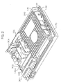
- This intermediate plate 142 has, mounted thereon, various kinds of devices stored into the upper box body 110. Examples of the devices mounted on the intermediate plate 142 include a disk unit 310, a slot unit 301, a power unit 302 and a switch-inlet unit 304 as shown in Fig. 2.
- a through hole 142b and a through hole 142c are also made in the intermediate plate 142 (see Fig. 1).
- a hood 142d is arranged in the intermediate plate 142 so as to cover the through hole 142b.
- a radiation fin 306 (see Fig. 2) arranged in the lower box body 170 extends through the through hole 142b, and is stored into the hood 142d.
- a notch portion 142a is formed in the intermediate plate 142 and a cooling fan 305 is arranged in the intermediate plate 142.
- the slot unit 301 is fastened to a projection arranged on an upper face of the intermediate plate 142 with a screw so that the slot unit 301 is fixed to the intermediate plate 142.
- the disk unit 310 is a recording medium drive unit for reproducing a disk type recording medium such as CD, DVD, etc., and has a tray (not shown) capable of sliding in and out.
- the disk type recording medium is to be mounted on the tray.
- a reproduction portion for storing the tray to reproduce the disk such as CD, DVD, etc. mounted on the tray is built in the disk unit 310.
- a notch portion 143a is formed in the rear face portion 141 of the central chassis 140.
- the switch-inlet unit 304 is exposed from the notch portion 143a to the exterior.
- An exhaust port 143b is formed in a position where the rear face portion 141 faces the cooling fan 305.
- various kinds of communication terminals 521, 522 are arranged in a lower rear face member 144.
- An opening portion 523 as an insertion port of an external memory device of an attaching-detaching type is made in the rear face portion 141. In a normal using state, the opening portion 523 is covered with a cover that is not shown.
- a main board 381 having a central processing unit 401 mounted thereon is arranged in the lower box body 170. Further, as shown in Fig. 5, a storing case 391 of the external memory device of the attaching-detaching type and a ventilation port 190 are arranged in the lower box body 170 together with the main board 381.
- the main board 381 has a two-layered structure constituted of a main substrate 381a and a substrate 381b for power.
- a heat sink 307 integrated with the radiation fin 306 and a shield 308 formed of a metallic plate are arranged between the two substrates.
- Required circuits can be efficiently stored in a limited space by forming the above two-layer structure in which the heat sink and the shield are sandwiched between the substrates.
- the central processing unit 401, a main memory device 402 and a drawing processor 403 are arranged as main parts in the main substrate 381a.
- a temperature sensor 404 is also arranged in the vicinity of the central processing unit 401.
- a connector portion 405 to be used for electric connection with the power substrate 381b and a signal line cable 406 to work as a signal path of data when the external memory device is mounted are further arranged on the main substrate 381a.
- Heat is generated by operation of the central processing unit 401, etc. arranged on the main substrate 381a. This heat is conducted to the heat sink 307 and is further conducted to the radiation fin 306.
- the air taken-in from the ventilation port 190 passes between respective fins of the radiation fin 306 when the air flows toward the cooling fan 305, whereby the air absorbs heat from the radiation fin 306.
- the air is exhausted from the cooling fan 305 to the exterior.
- the power substrate 381b is provided with a microcontroller 411 for controlling a voltage supplied to each device within the entertainment apparatus, a connector portion 412 to be used for electric connection with the main substrate 381a, an external memory device power line 413 for supplying the voltage when the external memory device is mounted, and a cooling fan power line 414 for supplying the voltage to the cooling fan 305.
- the microcontroller 411 can determine whether or not the external memory device is mounted by monitoring a state of the power line 413 of the external memory device. Further, the microcontroller 411 can obtain a temperature measured by the temperature sensor 404 through the connector portion 405 of the main substrate 381a and the connector portion 412 of the power substrate 381b.
- a general-purpose hard disk drive unit can be used as the external memory device to be mounted on this entertainment apparatus.
- the hard disk drive unit has a power connector portion and a data line connector portion.
- the external memory device power line 413 from the entertainment apparatus is connected to the power connector portion, and the signal line cable 406 is connected to the data line connector portion, so that the external memory device attains an operable state.
- the external memory device can then transmit and receive data in accordance with commands from the entertainment apparatus.
- the external memory device can be stored to a storing case 391, and attains a fixing state by closing a cover, so that the external memory device is stored in the entertainment apparatus.
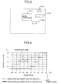
- the microcontroller 411 has a correspondence table for the fan control as data to be used for the control of the cooling fan, for example, as schematically shown in Fig. 9.
- a constitution in which the data to be used for the fan control is stored in the exterior of the microcontroller 411 and is referred to by the microcontroller 411.
- a format and values of the data to be used for the fan control are not limited to the example of this Figure. For example, a table format, a program format, etc., may be employed.
- the axis of ordinate shows the value of a voltage supplied to the cooling fan 305
- the axis of abscissa shows the temperature measured by the temperature sensor 404 arranged in the vicinity of the central processing unit 401.
- This table shows the relationship between a temperature range and the supplied voltage when the external memory device is mounted (a graph shown by a broken line) or not mounted (a graph shown by a solid line).
- the above temperature range applied with respect to a certain supplied voltage is called a temperature zone.
- a plurality of temperature zones are set for each of the time periods when the external memory device is mounted and not mounted.
- the present temperature zone when a certain temperature zone corresponding to the measured temperature is applied, and when the temperature rises and exceeds an upper limit of the present temperature zone, the present temperature zone is changed to a temperature zone for increasing the supplied voltage to the cooling fan 305, to increase the rotation number of the cooling fan 305. Conversely, when the temperature decreases to be lower than a lower limit of the present temperature zone, the present temperature zone is changed to a temperature zone for decreasing the supplied voltage to the cooling fan 305, to decrease the rotation number of the cooling fan 305.
- the voltage corresponding to the measured temperature can be accordingly supplied to the cooling fan 305.
- the microcontroller 411 supplies a higher voltage to the cooling fan 305 when the external memory device is mounted than when the external memory device is not mounted (provided that the case of supplying a highest voltage is excluded). That is because it is considered that heat sources and cooling objects are increased in number and the passage of a cooling air current becomes worse by mounting the external memory device. Further, that is because the influence of a noise generated by the cooling fan comes to be relatively low even when an increase in the rotation number makes the increased fan noise since the external memory device generates a noise.
- Adjacent temperature zones are respectively set so as to overlap by 0.5°C, so that so-called hysteresis characteristics are provided. Thus, a frequent change from one temperature zone to another is prevented when the measured temperature is close to a boundary of each temperature zone.
- a limit value of the temperature (74°C in the example of this Figure) is set, and when the measured temperature reaches the limit temperature, the microcontroller 411 stops supply of the voltage to the central processing unit 401 and the drawing processor 403.
- Fig. 10 is a flow chart for explaining processing by the microcontroller 411 in this case.
- the microcontroller 411 determines whether or not the external memory device is mounted from a state of the power line 413 of the external memory device. When the microcontroller 411 determines that the external memory device is mounted, the microcontroller 411 refers to the graph applied when the external memory device is mounted. When the microcontroller 411 determines that no external memory device is mounted, the microcontroller 411 refers to the graph applied when the external memory device is not mounted (S101).
- the microcontroller 411 initializes the temperature zone (S102).
- the temperature zone is set to a lowest range of the applied temperature in the initialization.
- the microcontroller 411 then supplies the cooling fan 305 with a voltage corresponding to this temperature zone.
- the value of a variable N as a counter is then set to zero (S103).
- the above counter is used to count the number of times of the measured temperature serially exceeding the present temperature zone range. This aims at changing one temperature zone to another when the measured temperature exceeds the present temperature zone in serial three temperature measurements by taking account of a case where noises, etc., cause a large error on the measured temperature.
- Two variables of the counter may be also used on upper and lower limit sides of the temperature zone.
- the microcontroller 411 obtains the temperature measured by the temperature sensor 404 near the central processing unit 401 (S104). The microcontroller 411 then refers to the correspondence table for the fan control, to determine whether or not the temperature reaches a limit value (S105). When the temperature reaches the limit value, the microcontroller 411 terminates the supply of the voltage to the central processing unit 401 and the drawing processor 403 (S106). When this temperature does not reach the limit value, the microcontroller 411 refers to the correspondence table for the fan control, to determine whether or not the obtained temperature is outside the range of the present temperature zone (S107).
- the value of the variable N is reset to zero (S108).
- the microcontroller 411 determines whether the external memory device is attached or detached from the state of the power line 413 of the external memory device (S113).
- the value of N is increased by one (S109).
- the microcontroller 411 determines whether or not the value of N comes to be 3 (S110). If the value of N is not 3, the microcontroller 411 does not change the temperature zone and determines the attachment-detachment of the external memory device since it determines that no change of temperature zones serially takes three times (S113). When the value of N is 3, the temperature zone is changed to another since it determines that the obtained temperature comes to be outside the range of the present temperature zone serially three times (S111).
- the microcontroller 411 changes the temperature zone to another temperature zone for increasing the voltage supplied to the cooling fan 305.
- the microcontroller 411 changes the temperature zone to another temperature zone for decreasing the voltage supplied to the cooling fan 305. Then, the value of the variable N is reset to zero (S112).
- the microcontroller 411 checks the state of the power line 413 of the external memory device, to determine whether or not there is a change in the attachment-detachment of the external memory device. As a result, when there is a change in the attachment-detachment, the process returns to the processing in S102, and the referred graph is changed to another, and the present temperature zone is set to that in an initial state when the external memory device is attached or detached. On the other hand, when there is no change in the attachment-detachment, the process returns to the processing in S104, and the temperature is obtained.
- the determination of attaching-detaching of the external memory device may be made separately from the processing shown in the flow chart of this Figure, and initialization processing (S102) of the temperature zone may be performed by interruption when there is a change in the attachment-detachment.
- any cycle time of the above series of processings for obtaining the temperature and determining the change in the temperature zone it can be set to, e.g., a predetermined period (250 m seconds, one second, etc.).
Landscapes
- Engineering & Computer Science (AREA)
- Theoretical Computer Science (AREA)
- Human Computer Interaction (AREA)
- Physics & Mathematics (AREA)
- General Engineering & Computer Science (AREA)
- General Physics & Mathematics (AREA)
- Cooling Or The Like Of Electrical Apparatus (AREA)
Abstract
Description
Claims (7)
- A method of controlling a cooling fan in an information processing device that permits internal mounting of a relevant device, comprising the steps of:obtaining an internal temperature of the information processing device;obtaining an attaching-detaching state of the relevant device;obtaining a value relative to a rotation speed of the cooling fan which rotation speed corresponds to the obtained temperature, by referring to data which shows the relationship between the value relative to the rotation speed of the cooling fan and the temperature, and is determined depending upon the attaching-detaching state of the relevant device; andcontrolling the rotation speed of the cooling fan on the basis of the value relative to the rotation speed of the cooling fan.
- An information processing device that permits internal mounting of a relevant device, comprising:wherein said control means determines the reference data to be referred to, on the basis of the attaching-detaching state of the relevant device obtained by the attaching-detaching state obtaining means, calculates the value relative to the rotation speed of the cooling fan from the temperature obtained by the temperature obtaining means and said reference data, and controls the rotation speed of the cooling fan on the basis of the obtained value.a cooling fan having variable rotation speeds,temperature obtaining means that obtains a temperature within the information processing device,attaching-detaching state obtaining means that obtains an attaching-detaching state of the relevant device,control means that controls the rotation speed of the cooling fan; andreference data storage means that stores reference data, which is determined depending upon attaching-detaching state of the relevant device, showing the relationship between a value relative to the rotation speed of the cooling fan and the temperature,
- The information processing device according to claim 2,
wherein said value relative to the rotation speed of the cooling fan is a voltage supplied to the cooling fan. - The information processing device according to claim 2,
wherein the reference data showing the relationship between the value relative to the rotation speed of the cooling fan and the temperature and being determined depending upon attaching-detaching state of said relevant device are determined such that, when the temperatures are at the same level, the rotation speed of the cooling fan when the relevant device is mounted is not smaller than the rotation speed of the cooling fan when the relevant device is not mounted. - The information processing device according to claim 2,
wherein said control means stops arithmetic processing of the information processing device when the temperature obtained by the temperature obtaining means is equal to, or greater than, a predetermined value. - A program executable by an information processing device that permits internal mounting of a relevant device and comprises a cooling fan able to change its rotation speed, temperature obtaining means that obtains a temperature within the information processing device, attaching-detaching state obtaining means that obtains an attaching-detaching state of the relevant device, and control means that controls the rotation speed of the cooling fan,
wherein the program causes said control means to execute the steps of:processing for referring to the reference data, which is determined depending upon the attaching-detaching state of the relevant device, showing the relationship between a value relative to the rotation speed of the cooling fan and the temperature; andprocessing for determining the reference data to be referred to, from the attaching-detaching state of the relevant device obtained by said attaching-detaching state obtaining means, calculating the value relative to the rotation speed of the cooling fan from the temperature obtained by the temperature obtaining means and said data for reference, and controlling the rotation speed of the cooling fan on the basis of this calculated value. - A recording medium that stores the program recited in claim 6 and is readable by an information processing device.
Applications Claiming Priority (3)
| Application Number | Priority Date | Filing Date | Title |
|---|---|---|---|
| JP2000325991A JP2002132387A (en) | 2000-10-25 | 2000-10-25 | Control method for cooling fan and information processor |
| JP2000325991 | 2000-10-25 | ||
| PCT/JP2001/009379 WO2002037247A1 (en) | 2000-10-25 | 2001-10-25 | Method of controlling cooling fan and information processing equipment |
Publications (2)
| Publication Number | Publication Date |
|---|---|
| EP1331545A1 true EP1331545A1 (en) | 2003-07-30 |
| EP1331545A4 EP1331545A4 (en) | 2009-03-18 |
Family
ID=18803266
Family Applications (1)
| Application Number | Title | Priority Date | Filing Date |
|---|---|---|---|
| EP01978908A Withdrawn EP1331545A4 (en) | 2000-10-25 | 2001-10-25 | Method of controlling cooling fan and information processing equipment |
Country Status (5)
| Country | Link |
|---|---|
| US (2) | US6587337B2 (en) |
| EP (1) | EP1331545A4 (en) |
| JP (1) | JP2002132387A (en) |
| AU (1) | AU2002210946A1 (en) |
| WO (1) | WO2002037247A1 (en) |
Families Citing this family (27)
| Publication number | Priority date | Publication date | Assignee | Title |
|---|---|---|---|---|
| TW494184B (en) * | 2001-11-14 | 2002-07-11 | Delta Electronics Inc | Fan control system by using a single-chip |
| US6914779B2 (en) * | 2002-02-15 | 2005-07-05 | Microsoft Corporation | Controlling thermal, acoustic, and/or electromagnetic properties of a computing device |
| US8905721B2 (en) * | 2002-07-12 | 2014-12-09 | Delta Electronics Inc. | Fan control system using a microcontroller |
| DE10303457B4 (en) * | 2003-01-29 | 2005-04-28 | Fujitsu Siemens Computers Gmbh | Fan controller for a processor fan |
| US7139169B2 (en) * | 2003-12-11 | 2006-11-21 | Dell Products L.P. | System and method for information handling system cooling fan operating parameter selection |
| US20050216221A1 (en) * | 2004-03-29 | 2005-09-29 | Broyles Paul J Iii | Systems and methods for cooling storage devices |
| CN2720766Y (en) * | 2004-06-16 | 2005-08-24 | 鸿富锦精密工业(深圳)有限公司 | Electronic apparatus housing-lid fixing device |
| JP2006286036A (en) * | 2005-03-31 | 2006-10-19 | Orion Denki Kk | Recording / playback device |
| JP2008084194A (en) * | 2006-09-28 | 2008-04-10 | Toshiba Corp | Controller, information processing apparatus, and communication control method |
| KR100797481B1 (en) * | 2007-01-18 | 2008-01-24 | 엘지전자 주식회사 | Refrigerator |
| DE202007006732U1 (en) * | 2007-01-26 | 2008-06-05 | Liebherr-Hausgeräte Ochsenhausen GmbH | Fridge and / or freezer |
| US7839636B2 (en) * | 2007-09-14 | 2010-11-23 | Ricoh Company, Limited | Image processing apparatus, fan control method, and energy-saving control device |
| US8341433B2 (en) * | 2008-01-04 | 2012-12-25 | Dell Products L.P. | Method and system for managing the power consumption of an information handling system |
| TWI398089B (en) * | 2009-03-02 | 2013-06-01 | 海韻電子工業股份有限公司 | Motor speed control method and circuit |
| US8716970B2 (en) | 2009-03-02 | 2014-05-06 | Sea Sonic Electronics Co., Ltd. | Method and circuit for controlling motors |
| US9081676B2 (en) * | 2009-06-02 | 2015-07-14 | Lenovo Enterprise Solutions (Singapore) Pte. Ltd. | Operating computer memory |
| TWM374620U (en) * | 2009-10-05 | 2010-02-21 | Ibase Technology Inc | Digital signboard player |
| JP5699781B2 (en) * | 2011-04-27 | 2015-04-15 | 日本電気株式会社 | Fan failure notification device and method thereof |
| JP2013020500A (en) * | 2011-07-12 | 2013-01-31 | Lenovo Singapore Pte Ltd | Cooling system, portable type information apparatus, external device, temperature control method for portable information apparatus, and computer executable program |
| JP5895184B2 (en) * | 2011-09-21 | 2016-03-30 | パナソニックIpマネジメント株式会社 | Electric tool |
| JP5452644B2 (en) * | 2012-03-08 | 2014-03-26 | アンリツ株式会社 | Measuring apparatus and measuring method |
| JP5795744B2 (en) * | 2012-03-15 | 2015-10-14 | アンリツ株式会社 | Measuring apparatus and measuring method |
| TW201416839A (en) * | 2012-10-30 | 2014-05-01 | Hon Hai Prec Ind Co Ltd | System and method for controlling temperatures of a processor |
| BR112015028495B1 (en) | 2013-05-17 | 2022-09-06 | Sony Computer Entertainment Inc | ELECTRONIC DEVICE AND METHOD FOR MANUFACTURING AN ELECTRONIC DEVICE |
| EP2998825B1 (en) | 2013-05-17 | 2018-11-28 | Sony Interactive Entertainment Inc. | Electronic device |
| US9903381B2 (en) * | 2015-02-13 | 2018-02-27 | Delta Electronics, Inc. | System and method for controlling forward/reverse rotation of fan |
| CN105889109B (en) * | 2015-02-13 | 2018-02-09 | 台达电子工业股份有限公司 | Control system for controlling positive and negative rotation of fan and applicable control method thereof |
Family Cites Families (12)
| Publication number | Priority date | Publication date | Assignee | Title |
|---|---|---|---|---|
| JPH01226012A (en) * | 1988-03-07 | 1989-09-08 | Toshiba Corp | Cooling device for electronic apparatus |
| JPH0310308A (en) * | 1989-06-07 | 1991-01-17 | Nec Gumma Ltd | Power supply device for information processor |
| US5249741A (en) | 1992-05-04 | 1993-10-05 | International Business Machines Corporation | Automatic fan speed control |
| JPH10320071A (en) * | 1997-05-23 | 1998-12-04 | Rohm Co Ltd | Semiconductor integrated circuit |
| US5864464A (en) * | 1997-06-09 | 1999-01-26 | Lin; Alex | Heat sink for integrated circuit |
| JPH1185323A (en) * | 1997-09-01 | 1999-03-30 | Toshiba Corp | Computer system and temperature control method thereof |
| US6061237A (en) * | 1998-12-21 | 2000-05-09 | Dell Usa, L.P. | Computer with an improved cooling system and a method for cooling a computer |
| US6380704B1 (en) * | 1999-05-10 | 2002-04-30 | Silicon Touch Technology Inc. | Fan linear speed controller |
| US6188189B1 (en) * | 1999-12-23 | 2001-02-13 | Analog Devices, Inc. | Fan speed control system |
| US6340874B1 (en) * | 2000-05-30 | 2002-01-22 | Daystream Info Inc | Method and apparatus utilized in computer type systems for control of variable speed fans to reduce their noise |
| US6528987B1 (en) * | 2000-06-19 | 2003-03-04 | Analog Devices, Inc. | Method and apparatus for determining fan speed |
| US6512673B1 (en) * | 2000-07-05 | 2003-01-28 | Network Engines, Inc. | Low profile equipment housing with angular fan |
-
2000
- 2000-10-25 JP JP2000325991A patent/JP2002132387A/en active Pending
-
2001
- 2001-10-25 US US10/002,960 patent/US6587337B2/en not_active Expired - Lifetime
- 2001-10-25 EP EP01978908A patent/EP1331545A4/en not_active Withdrawn
- 2001-10-25 WO PCT/JP2001/009379 patent/WO2002037247A1/en not_active Ceased
- 2001-10-25 AU AU2002210946A patent/AU2002210946A1/en not_active Abandoned
-
2003
- 2003-04-23 US US10/421,589 patent/US6977812B2/en not_active Expired - Lifetime
Also Published As
| Publication number | Publication date |
|---|---|
| JP2002132387A (en) | 2002-05-10 |
| EP1331545A4 (en) | 2009-03-18 |
| US20020085353A1 (en) | 2002-07-04 |
| US6587337B2 (en) | 2003-07-01 |
| AU2002210946A1 (en) | 2002-05-15 |
| WO2002037247A1 (en) | 2002-05-10 |
| US6977812B2 (en) | 2005-12-20 |
| US20030202325A1 (en) | 2003-10-30 |
Similar Documents
| Publication | Publication Date | Title |
|---|---|---|
| EP1331545A1 (en) | Method of controlling cooling fan and information processing equipment | |
| US7120016B2 (en) | Disk array device | |
| US6935130B2 (en) | Computer cooling system | |
| US5410448A (en) | Adaptive cooling system | |
| US5886639A (en) | Memory storage device housing and cooling device | |
| EP1107093B1 (en) | Thermal control for a test and measurement instrument | |
| US20060016901A1 (en) | Cooling system with a variable maximum operation level | |
| EP1988760A1 (en) | Temperature control device, management device, system and method | |
| JPH087994B2 (en) | Electric device with forced air cooling | |
| JP2001210981A (en) | Electronic appliance having radiating structure, and television-game machine having the radiating structure | |
| KR20200106758A (en) | Blower for ventilating seat and Seat ventilation system having the same | |
| EP1507264A2 (en) | Disc recording and/or reproducing apparatus | |
| US20050018399A1 (en) | Electronic apparatus with cooling fan | |
| US6628519B2 (en) | Computer having a function for controlling temperature of file bays | |
| US7245487B2 (en) | Cooling system, electronic equipment, and external unit | |
| US20050122680A1 (en) | Cooling structure and cooling method for electronic equipment | |
| US7690008B2 (en) | Optical disc drive having openings in the housing to allow air therein | |
| KR20060050829A (en) | Computer cooling system using thermoelectric elements, air-cooled kits and ducts | |
| JP4254438B2 (en) | Test board equipment | |
| US20040190416A1 (en) | Integrating configuration of combined electronic equipment | |
| EP3499339B1 (en) | Electronics device and method of cooling | |
| JP2006108324A (en) | Electronic device | |
| CN101331551B (en) | disk device | |
| US20050210485A1 (en) | Disk device with enhanced heat radiation effects | |
| US7290270B2 (en) | Optical disk apparatus |
Legal Events
| Date | Code | Title | Description |
|---|---|---|---|
| PUAI | Public reference made under article 153(3) epc to a published international application that has entered the european phase |
Free format text: ORIGINAL CODE: 0009012 |
|
| 17P | Request for examination filed |
Effective date: 20020725 |
|
| AK | Designated contracting states |
Designated state(s): AT BE CH CY DE DK ES FI FR GB GR IE IT LI LU MC NL PT SE TR |
|
| RBV | Designated contracting states (corrected) |
Designated state(s): AT BE DE GB |
|
| A4 | Supplementary search report drawn up and despatched |
Effective date: 20090216 |
|
| 17Q | First examination report despatched |
Effective date: 20090610 |
|
| RAP1 | Party data changed (applicant data changed or rights of an application transferred) |
Owner name: SONY COMPUTER ENTERTAINMENT INCORPORATED |
|
| RAP1 | Party data changed (applicant data changed or rights of an application transferred) |
Owner name: SONY COMPUTER ENTERTAINMENT INC. |
|
| RAP1 | Party data changed (applicant data changed or rights of an application transferred) |
Owner name: SONY INTERACTIVE ENTERTAINMENT INC. |
|
| STAA | Information on the status of an ep patent application or granted ep patent |
Free format text: STATUS: THE APPLICATION IS DEEMED TO BE WITHDRAWN |
|
| 18D | Application deemed to be withdrawn |
Effective date: 20160524 |