EP1331530A2 - Electronic timepiece - Google Patents
Electronic timepiece Download PDFInfo
- Publication number
- EP1331530A2 EP1331530A2 EP03250352A EP03250352A EP1331530A2 EP 1331530 A2 EP1331530 A2 EP 1331530A2 EP 03250352 A EP03250352 A EP 03250352A EP 03250352 A EP03250352 A EP 03250352A EP 1331530 A2 EP1331530 A2 EP 1331530A2
- Authority
- EP
- European Patent Office
- Prior art keywords
- display unit
- liquid crystal
- crystal panel
- unit housing
- electric terminals
- Prior art date
- Legal status (The legal status is an assumption and is not a legal conclusion. Google has not performed a legal analysis and makes no representation as to the accuracy of the status listed.)
- Withdrawn
Links
Images


Classifications
-
- G—PHYSICS
- G04—HOROLOGY
- G04G—ELECTRONIC TIME-PIECES
- G04G17/00—Structural details; Housings
- G04G17/02—Component assemblies
- G04G17/06—Electric connectors, e.g. conductive elastomers
-
- G—PHYSICS
- G04—HOROLOGY
- G04G—ELECTRONIC TIME-PIECES
- G04G17/00—Structural details; Housings
- G04G17/02—Component assemblies
- G04G17/04—Mounting of electronic components
- G04G17/045—Mounting of the display
Definitions
- This invention relates to an electronic timepiece in which the reliability of the electrical connection of terminals made when a display unit is fitted diagonally into a housing is improved.
- the construction of a related art electronic timepiece is shown in Fig. 5.
- the related art electronic timepiece generally has a structure in which a display unit 511 formed by holding in a housing 515 a liquid crystal panel 516, an electroluminescence panel (which will hereinafter be referred to as "EL panel") 517, and a coiled spring 514 electrically connecting the EL panel 517 and a circuit board 512 together; and a driving circuit mounted with an integrated circuit and electric elements so as to supply an electric signal to the liquid crystal panel 516 and EL panel 517 are connected together by conductive rubber, a photoseal and a coiled spring.
- a display unit 511 formed by holding in a housing 515 a liquid crystal panel 516, an electroluminescence panel (which will hereinafter be referred to as "EL panel”) 517, and a coiled spring 514 electrically connecting the EL panel 517 and a circuit board 512 together; and a driving circuit mounted with an integrated circuit and electric elements so as to supply an
- the display unit 511 is combined with the circuit board 512 as the display unit 511 is lowered vertically with respect the circuit board 512, so that a load is imparted to contact terminals, such as the conductive rubber 518 and coiled spring 514 vertically as well. Therefore, positions of the coiled spring and conductive rubber do not horizontally shift when these parts are bent.
- the present invention has been made in view of these circumstances, and is to provide an electronic timepiece in which a horizontal slippage of contact terminals occurring when a contact terminal-mounted display unit is fitted diagonally in a case is suppressed and the electrical connection of the terminals is secured.
- the invention provides an electronic timepiece comprising a liquid crystal panel, a backlight provided on a rear surface of and adapted to illuminate the liquid crystal panel, electric terminals one end of each of which is electrically connected to a rear surface of the backlight, and the other end of each of which is electrically connected to a circuit board, and a display unit housing holding the liquid crystal panel and the backlight therein, and having guide holes for inserting the electric terminals thereinto and retaining the same therein, the guide holes in the display unit housing having bores thereunder the diameter of each of which is larger than that of each of the guide holes so as to prevent a force exerted on the electric terminals when the electric terminals are inserted into the guide holes during an operation for diagonally fitting the display unit housing into a case with the liquid crystal panel, the backlight and electric terminals in a firmly combined state from causing the electric terminals in the mentioned state inserted into the display unit housing to slip in a horizontal direction.
- the invention also provides an electronic timepiece, in which (3 is assumed to be an angle at which each of the electric terminals of a length L1 and an outer diameter D1 falls in the relative guide hole, which has a length L2 and a diameter D2, when the display unit housing is fitted in the case diagonally at an angle ⁇ , a diameter D3 of the bore then having the following relation to the other sizes.
- the bores have the above-described relation to other parts, the bores have not to be enlarged to a level higher than a required level.
- the invention further provides an electronic timepiece, in which the liquid crystal panel is a film liquid crystal panel, the film liquid crystal panel being connected to the circuit board by film-like materials, the film-like materials by which the film liquid crystal panel and circuit board are connected together having a plurality of different lengths.
- the invention furthermore provides an electronic timepiece which is an electronic timepiece using a display unit housing which retains electric terminals of coiled springs which electrically connect an EL panel to a driving circuit, each of guide holes for the electric terminals being formed so that the guide hole has at a driving circuit-side portion thereof a tapering bore a diameter of which is set to a level determined on the basis of an angle at which the electric terminal of the coiled spring diagonally contacts the driving circuit when the display unit housing is diagonally fitted in a case.
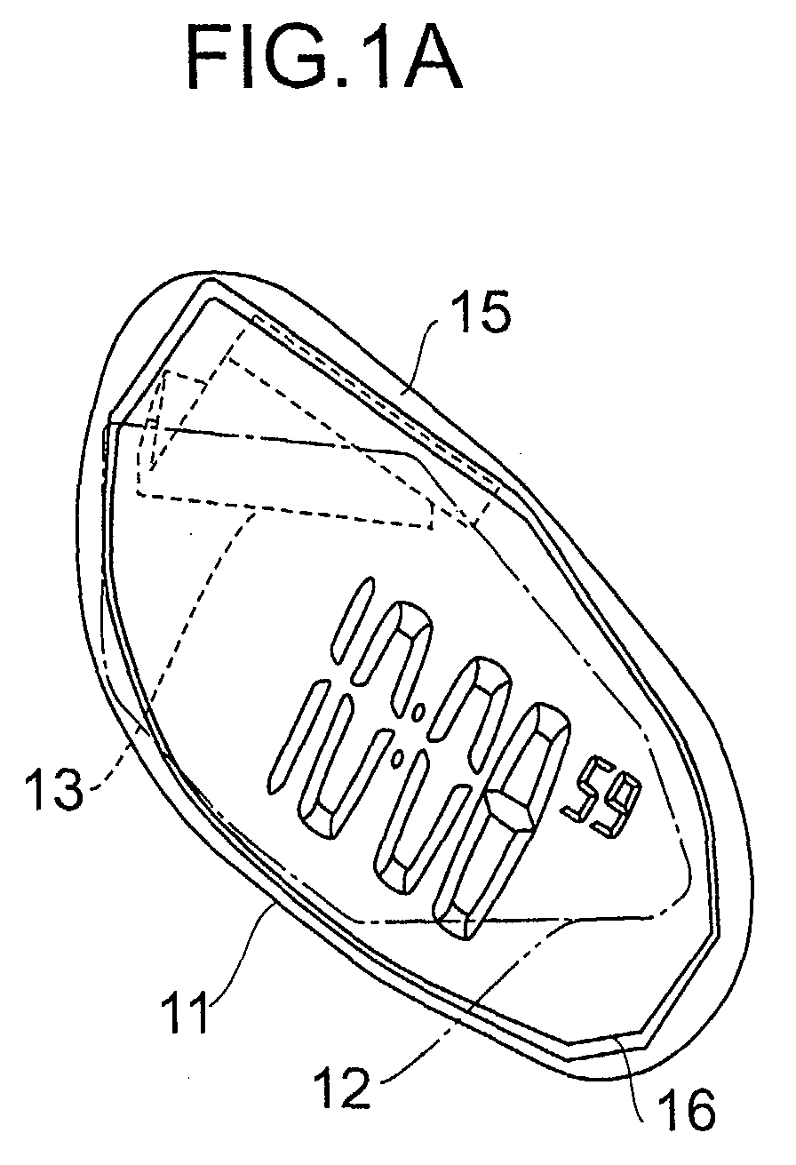
- Figs. 1 are a general plan view 1A and a sectional view 1B of the electronic timepiece according to the present invention.
- the electronic timepiece according to the invention has a film liquid crystal panel 16, an EL panel 17 and electric terminals 14 of coiled springs all of which are held in a display unit housing 15.
- the film liquid crystal panel 16 is provided with the EL panel 17 on the rear side thereof.
- the film liquid crystal panel 16 is electrically connected to a driving circuit 12 provided on the rear side thereof, by a heat seal 13.
- the EL panel 17 is used as a back light for the liquid crystal panel 16.
- Each of the electric terminals 14 of coiled springs is engaged at one end thereof with a rear surface of the EL panel 17, and at the other end thereof with the driving circuit 12.
- Each electric terminal 14 of coiled spring is inserted into a two-stage through bore provided in the display unit housing 15.
- the diameter of the portion of the through bore which is on the side of the EL panel 17 is set larger.
- the outer diameter of a part of the electric terminal 14 of coiled spring is increased so that the mentioned part of the electric terminal is fitted closely in the diameter-increased part of the through bore.
- the electric terminal 14 of coiled spring is then sandwiched between the EL panel 17 and display unit housing 15 and thereby held firmly.
- the display unit housing 15 (which will hereinafter be referred to as "display module"), in which the film liquid crystal panel 16 is provided, and circuit board 12 are fixed to a case. During the fixing of the display module to the case 18, the driving circuit 12 is secured to the case first by screws.
- Fig. 2 is an expansion plan showing the heat seal, display unit and driving circuit, which are arranged in a plane, in the electronic timepiece according to the present invention.
- the driving circuit 12 and display unit housing 15 are joined to each other by a part shaped so that the heat seal 13 thereof is partly shortened in conformity with the design of the case 18.
- Fig. 3 is a drawing showing the display unit housing diagonally fitted in a case in the electronic timepiece according to the present invention.
- the display unit housing 15 is fitted into the case as the display unit housing is inclined.
- the electric terminals of coiled springs are deformed axially, and a diagonal force is also exerted thereon.
- the electric terminals of coiled springs are moved in the through bores of the display housing 15 in a direction as well which is different from the axial direction. The detailed behaviors of the electric terminals will be described with reference to Fig. 4.
- Fig. 4 is a detail drawing of an electric terminal 14 of coiled spring in the condition in which the display unit housing 15 of Fig. 3 is diagonally fitted in the case.
- the display unit housing fitting operation is started by inclining the display unit housing 15 at an angle of ⁇ degrees from the horizontal, and further put forward. Finally, the display unit housing 15 in an inclined state becomes horizontal.
- a load is imparted on the electric terminal 14 as well first at an angle of ⁇ degrees from the vertical so as to diagonally compress the coiled spring.
- the spring compressing angle decreases gradually, and becomes zero degree finally, so that a load is imparted to the coiled spring in the vertical direction.
- D1 an outer diameter 41 of an electric terminal 14 of coiled spring
- D2 a diameter 42 of a guide hole for the electric terminal of coiled spring in the display unit housing
- D3 a diameter of the portion of a tapering opening 43 of the guide hole in the display unit housing which is on the side of the driving circuit
- L1 the length 44 of the coiled spring
- L2 the length 45 of the guide hole for the electric terminal of coiled spring of the display unit housing 15
- ⁇ degrees an angle of a flexure load imparted to the coiled spring when the display unit 11 is diagonally fitted into the case.
- the D3, the diameter of the portion of the tapering opening 43 of the guide hole in the display unit housing which is on the side of the driving circuit is determined by the following equations.
- ⁇ represents an angle at which each of the electric terminals of coiled springs falls in the relative guide hole in the display unit housing when a force of an angle ⁇ is exerted to the same electric terminal.
- D3 D2+2 ⁇ (L1- ⁇ ((L2)2+(D2-D1)2)) ⁇ (sin ⁇ +tan ⁇ xcos ⁇ ) ⁇ TAN -1 ((D2-D1)/L2)
- liquid crystal panel using a glass board may also be employed.
- tapering bores are provided in the guide holes of the display unit housing. Therefore, when the display unit housing mounted with the electric terminals inserted into the guide holes is fitted diagonally into the case, the openings allow the behavior of the electric terminals in the housing fitting operation. This enables the slippage of the horizontal position of the electric terminals to be minimized. Since the horizontal slippage of the electric terminals can be minimized, the degree of freedom of setting the positions of the terminals of the film liquid crystal panel and EL panel increases, and an electronic timepiece having a case of a further improved design can be provided.
Landscapes
- Physics & Mathematics (AREA)
- General Physics & Mathematics (AREA)
- Electric Clocks (AREA)
- Devices For Indicating Variable Information By Combining Individual Elements (AREA)
Abstract
Description
Claims (4)
- An electronic timepiece comprising:a liquid crystal panel,a backlight provided on a rear surface of and adapted to illuminate the liquid crystal panel,electric terminals one end of each of which is electrically connected to a rear surface of the backlight,
and the other end of each of which is electrically connected to a circuit board, anda display unit housing holding the liquid crystal panel and the backlight therein, and having guide holes for inserting the electric terminals thereinto and retaining the same therein, wherein the guide holes in the display unit housing have bores thereunder the diameter of each of which is larger than that of each of the guide holes so as to prevent a force exerted on the electric terminals when the electric terminals are inserted into the guide holes during an operation for diagonally fitting the display unit housing into a case with the liquid crystal panel, the backlight and electric terminals in a firmly combined state from causing the electric terminals in the mentioned state inserted into the display unit housing to slip in a horizontal direction. - An electronic timepiece according to Claim 1, wherein, β is assumed to be an angle at which each of the electric terminals of a length L1 and an outer diameter D1 falls in the relative guide hole, which has a length L2 and a diameter D2, when the display unit housing is fitted in the case diagonally at an angle α, a diameter D3 of the bore under the guide hole then having the following relation to the other sizes.
- An electronic timepiece according to Claim 1, wherein the liquid crystal panel is a film liquid crystal panel, the film liquid crystal panel being connected to the circuit board by film-like materials, the film-like materials by which the film liquid crystal panel and circuit board are connected together having a plurality of different lengths.
- An electronic timepiece as claimed in any one of claims 1 to 3 wherein the backlight comprises an electroluminescence panel.
Applications Claiming Priority (2)
| Application Number | Priority Date | Filing Date | Title |
|---|---|---|---|
| JP2002015935 | 2002-01-24 | ||
| JP2002015935A JP2003215278A (en) | 2002-01-24 | 2002-01-24 | Electronic clock |
Publications (2)
| Publication Number | Publication Date |
|---|---|
| EP1331530A2 true EP1331530A2 (en) | 2003-07-30 |
| EP1331530A3 EP1331530A3 (en) | 2004-06-30 |
Family
ID=19191983
Family Applications (1)
| Application Number | Title | Priority Date | Filing Date |
|---|---|---|---|
| EP03250352A Withdrawn EP1331530A3 (en) | 2002-01-24 | 2003-01-21 | Electronic timepiece |
Country Status (4)
| Country | Link |
|---|---|
| US (1) | US6798721B2 (en) |
| EP (1) | EP1331530A3 (en) |
| JP (1) | JP2003215278A (en) |
| CN (1) | CN1434357A (en) |
Cited By (1)
| Publication number | Priority date | Publication date | Assignee | Title |
|---|---|---|---|---|
| EP2485100A1 (en) * | 2011-02-08 | 2012-08-08 | ETA SA Manufacture Horlogère Suisse | Watch including a bezel and method for attaching such a bezel |
Families Citing this family (1)
| Publication number | Priority date | Publication date | Assignee | Title |
|---|---|---|---|---|
| JP2016027341A (en) * | 2015-09-28 | 2016-02-18 | カシオ計算機株式会社 | Vibration device, timing device and electronic device |
Family Cites Families (10)
| Publication number | Priority date | Publication date | Assignee | Title |
|---|---|---|---|---|
| US4208869A (en) * | 1976-07-31 | 1980-06-24 | Citizen Watch Co., Ltd. | Illumination device for electronic timepiece |
| US4391531A (en) * | 1980-12-19 | 1983-07-05 | Timex Corporation | Electrooptical display/lead frame subassembly and timepiece module including same |
| JPS5993155U (en) * | 1982-12-15 | 1984-06-25 | シャープ株式会社 | Electronic equipment with solar cells |
| US4624529A (en) * | 1984-11-16 | 1986-11-25 | Timex Corporation | Liquid crystal display with central interconnections |
| US4985878A (en) * | 1988-09-12 | 1991-01-15 | Casio Computer Co., Ltd. | Electronic timepiece with analog time display unit and electrooptic data display unit |
| US4904213A (en) * | 1989-04-06 | 1990-02-27 | Motorola, Inc. | Low impedance electric connector |
| US5528463A (en) * | 1993-07-16 | 1996-06-18 | Dallas Semiconductor Corp. | Low profile sockets and modules for surface mountable applications |
| JP3564207B2 (en) * | 1995-08-31 | 2004-09-08 | セイコーエプソン株式会社 | Portable electronic equipment |
| JPH1115394A (en) * | 1997-06-20 | 1999-01-22 | Casio Comput Co Ltd | Electronic components, electronic devices, and watches using them |
| WO2000003310A1 (en) * | 1998-07-10 | 2000-01-20 | Citizen Watch Co., Ltd. | Timepiece |
-
2002
- 2002-01-24 JP JP2002015935A patent/JP2003215278A/en active Pending
-
2003
- 2003-01-16 US US10/345,754 patent/US6798721B2/en not_active Expired - Fee Related
- 2003-01-21 EP EP03250352A patent/EP1331530A3/en not_active Withdrawn
- 2003-01-24 CN CN03102984.1A patent/CN1434357A/en active Pending
Cited By (3)
| Publication number | Priority date | Publication date | Assignee | Title |
|---|---|---|---|---|
| EP2485100A1 (en) * | 2011-02-08 | 2012-08-08 | ETA SA Manufacture Horlogère Suisse | Watch including a bezel and method for attaching such a bezel |
| WO2012107408A1 (en) * | 2011-02-08 | 2012-08-16 | Eta Sa Manufacture Horlogere Suisse | Watch including a bezel, and method for attaching such bezel |
| US9501039B2 (en) | 2011-02-08 | 2016-11-22 | Eta Sa Manufacture Horlogere Suisse | Watch including a bezel and method of attaching such bezel |
Also Published As
| Publication number | Publication date |
|---|---|
| EP1331530A3 (en) | 2004-06-30 |
| US20030142589A1 (en) | 2003-07-31 |
| JP2003215278A (en) | 2003-07-30 |
| US6798721B2 (en) | 2004-09-28 |
| CN1434357A (en) | 2003-08-06 |
Similar Documents
| Publication | Publication Date | Title |
|---|---|---|
| US6025644A (en) | Liquid crystal display and apparatus using the same | |
| US5066235A (en) | Connector assembly for electronic devices | |
| US6514089B2 (en) | Terminal connecting device for flexible substrate | |
| KR101515826B1 (en) | Camera module having MEMS actuator | |
| US6798721B2 (en) | Electronic timepiece | |
| JP2000155306A (en) | Display device | |
| JP2000067966A (en) | Electrical connector | |
| US6969263B2 (en) | Electrical connector assembly | |
| KR100485967B1 (en) | Pressure-bonded substrate, liquid crystal device, and electronic device | |
| US6373716B1 (en) | Printed circuit board for surface connection and electronic apparatus employing the same | |
| US6769922B1 (en) | Auxillary connectors for connectors of liquid crystal display device | |
| US7258550B2 (en) | Electrical connector assembly | |
| US6040846A (en) | Impact resistant display apparatus | |
| CN115701626B (en) | Display module and display device including the display module | |
| JP2000134021A (en) | Portable radio | |
| JPH1032061A (en) | Instrument panel connector | |
| JP2003346963A (en) | Electrical connector | |
| JPH07302633A (en) | Speaker connection structure in communication equipment | |
| KR100800686B1 (en) | LCD module and liquid crystal imaging means using the same | |
| JPH1022008A (en) | Memory card loading device | |
| KR100950674B1 (en) | Backlight lamp fixing socket | |
| JP4535939B2 (en) | Hole reinforcing member and substrate support structure | |
| JPH1138890A (en) | Liquid crystal display holding device | |
| JP2583995Y2 (en) | Connecting piece and circuit connection structure | |
| JP2003163434A (en) | Jack mounting structure and small electronic equipment |
Legal Events
| Date | Code | Title | Description |
|---|---|---|---|
| PUAI | Public reference made under article 153(3) epc to a published international application that has entered the european phase |
Free format text: ORIGINAL CODE: 0009012 |
|
| AK | Designated contracting states |
Designated state(s): AT BE BG CH CY CZ DE DK EE ES FI FR GB GR HU IE IT LI LU MC NL PT SE SI SK TR |
|
| AX | Request for extension of the european patent |
Extension state: AL LT LV MK RO |
|
| PUAL | Search report despatched |
Free format text: ORIGINAL CODE: 0009013 |
|
| AK | Designated contracting states |
Kind code of ref document: A3 Designated state(s): AT BE BG CH CY CZ DE DK EE ES FI FR GB GR HU IE IT LI LU MC NL PT SE SI SK TR |
|
| AX | Request for extension of the european patent |
Extension state: AL LT LV MK RO |
|
| AKX | Designation fees paid | ||
| REG | Reference to a national code |
Ref country code: DE Ref legal event code: 8566 |
|
| STAA | Information on the status of an ep patent application or granted ep patent |
Free format text: STATUS: THE APPLICATION IS DEEMED TO BE WITHDRAWN |
|
| 18D | Application deemed to be withdrawn |
Effective date: 20041231 |