EP1331502A2 - Optical cable housing an optical unit surrounded by a plurality of gel layers - Google Patents
Optical cable housing an optical unit surrounded by a plurality of gel layers Download PDFInfo
- Publication number
- EP1331502A2 EP1331502A2 EP03001269A EP03001269A EP1331502A2 EP 1331502 A2 EP1331502 A2 EP 1331502A2 EP 03001269 A EP03001269 A EP 03001269A EP 03001269 A EP03001269 A EP 03001269A EP 1331502 A2 EP1331502 A2 EP 1331502A2
- Authority
- EP
- European Patent Office
- Prior art keywords
- gel layer
- viscosity
- optical
- gel
- yield stress
- Prior art date
- Legal status (The legal status is an assumption and is not a legal conclusion. Google has not performed a legal analysis and makes no representation as to the accuracy of the status listed.)
- Granted
Links
Images


Classifications
-
- G—PHYSICS
- G02—OPTICS
- G02B—OPTICAL ELEMENTS, SYSTEMS OR APPARATUS
- G02B6/00—Light guides; Structural details of arrangements comprising light guides and other optical elements, e.g. couplings
- G02B6/44—Mechanical structures for providing tensile strength and external protection for fibres, e.g. optical transmission cables
- G02B6/4401—Optical cables
- G02B6/4429—Means specially adapted for strengthening or protecting the cables
-
- G—PHYSICS
- G02—OPTICS
- G02B—OPTICAL ELEMENTS, SYSTEMS OR APPARATUS
- G02B6/00—Light guides; Structural details of arrangements comprising light guides and other optical elements, e.g. couplings
- G02B6/44—Mechanical structures for providing tensile strength and external protection for fibres, e.g. optical transmission cables
- G02B6/4401—Optical cables
- G02B6/4429—Means specially adapted for strengthening or protecting the cables
- G02B6/44384—Means specially adapted for strengthening or protecting the cables the means comprising water blocking or hydrophobic materials
Definitions
- the present invention relates to an optical fiber cable comprising an optical unit and a plurality of gel layers surrounding the optical unit.
- the present invention relates to an optical fiber cable comprising a buffer tube housing an optical unit and a plurality of gel layers having different rheological properties surrounding an optical fiber.
- Optical fiber cables are used to transmit information at very high rates over long distances.
- Optical fiber cables may be classified into three general classifications based on cable structure: loose tube, monotube, and slotted core.
- loose tube and monotube cables buffer tubes are utilized as the primary structure for protecting the thin optical fibers contained within.
- the buffer tubes typically house an optical unit such as one or more loose optical fibers or an optical fiber ribbon stack having a plurality of optical fibers held together in a planar array by a common matrix material.
- a plurality of buffer tubes are stranded, helically or reverse helically, around a central strength member to form a stranded core.
- filler rods may be stranded around the central strength member in order to provide symmetry in design for fiber counts lower than that of a full fiber count cable.
- one or more optical fibers are housed in a single, centrally located buffer tube.
- the buffer tubes or stranded core is jacketed with an additional protective layer.
- reinforcing yarns or fibers as well as waterblocking materials in the form of gels or hot melts, water swellable powers, yarns or tapes, and/or corrugated armor may be place between the jacket and the inner cable layers.
- the optical fibers reside in channels or slots which are generally filled with a gel material. These channels form a helical path along the longitudinal axis of the cable.
- Buffer tubes are typically made from "engineering resins” such as polybutylene terepthalate (PBT), polycarbonate (PC), polyamides such as nylon-12, polyolefin materials such as polyethylene-polypropylene copolymers and isotactic polypropylene (I-PP), or some layer combination of the above. See U.S. Patent No. 6,085,009.
- engineing resins such as polybutylene terepthalate (PBT), polycarbonate (PC), polyamides such as nylon-12, polyolefin materials such as polyethylene-polypropylene copolymers and isotactic polypropylene (I-PP), or some layer combination of the above. See U.S. Patent No. 6,085,009.
- the buffer tubes may be filled with a water blocking compound such as a thixotropic gel to prevent water ingress while allowing fiber movement during cable expansion or contraction.
- a water blocking compound such as a thixotropic gel
- water swellable or superabsorbent materials such as tape, power or yarn formed of polyacrylates with carboxylate functional groups, partially neutralized polyacrylic acid, polyamides, or copolymers thereof, which can absorb water in the buffer tubes.
- a secondary low molecular weight oil to pre-wet the optical fibers and optical fiber ribbons in order to prevent water migration down interstices through the optical unit by way of capillary action.
- buffer tubes are typically manufactured with a single thixotropic gel surrounding the optical unit.
- the yield stress of the gel allows the optical unit to freely move within the buffer tube so that the optical fiber may drift to locations other than the axial center of the buffer tube.
- the thixotropic gel material generally includes a thickening or gelling agent in a liquid carrier.
- a thickening or gelling agent in a liquid carrier.
- three types of gels materials have been used in fiber-optic cables: (1) gels based on polar oils such as polyols; (2) gels based on natural or synthetic hydrocarbon oils; and (3) gels based on silicone oils.
- Organic and non-organic thickeners are typically present as relatively isometric colloidal particles.
- Gelling agents form a physical network structure in which the polymeric base oil molecules interact with the gelling agent through entanglements, adsorption onto the surface of particles such as pyrogenic silica, and/or some other secondary interaction.. When a low stress is applied to a gel-like composition, the material acts substantially as a solid.
- gel materials which are compatible with the material of the buffer tube may not be compatible with or protective of the optical unit it surrounds.
- Non-compatible gel materials can swell buffer tube polymers and are able to extract the additives therein and reduce the thermo-oxidative stability of the buffer tubes.
- U.S. Patent No. 6,085,009 discloses a water blocking gel which is compatible with polyefin buffer tubes and is made of a polyolefin oil, wherein only a very small fraction of the polyolefin species have a molecular weight below about 2000.
- the present invention is adapted to provide an optical fiber cable including a buffer tube structure wherein the optical unit is located in the buffer tube and protected from contact with an inner wall of the buffer tube.
- an optical fiber cable comprising a buffer tube housing an optical unit including at least one optical fiber, and at least first and second gel layers interposed between the buffer tube and the optical unit, wherein the first and second gel layers have different rheological properties.
- the first gel layer surrounds the optical unit and the second gel layer surrounds the first gel layer.
- the inner gel layer may have a yield stress and a viscosity which are lower than a yield stress and a viscosity of the outer gel layer.
- the lower yield stress and viscosity of the inner gel layer serve to maintain the optical unit in an axial center position within the buffer tube and facilitate easy re-positioning of the optical unit to the axial center position when the buffer tube is flexed or bent. As a result, the optical unit may be maintained in a low stress state and stress-induced attenuation may be prevented.
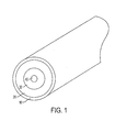
- the optical fiber cable structure in accordance with a preferred embodiment of the present invention comprises a buffer tube 10 housing an optical fiber unit 40 such as one or more optical fibers or an optical fiber ribbon stack. Interposed between the buffer tube 10 and the optical fiber unit 40 is a first or inner gel layer 30 and a second or outer gel layer 20.
- the inner gel layer 30 surrounds the optical fiber unit 40 and the outer gel layer 20 surrounds the inner gel layer 30 and contacts an inner wall surface of the buffer tube 10.
- the inner gel layer 30 and the outer gel layer 20 may have different rheological properties such that the inner gel layer has a yield stress and a viscosity which are lower than a yield stress and a viscosity of the outer gel layer 20.
- the lower yield stress and viscosity of the inner gel layer 30 serves to maintain the optical unit 40 substantially in an axial center position within the buffer tube 10 and facilitates easy re-positioning of the optical unit 40 to the axial center position when the optical fiber cable is flexed.
- the optical unit 40 may be offset from the axial center of the buffer tube 10 as long as it is protected by the inner and outer gel layers 30 and 20 from contact with the inner wall of the buffer tube 10.
- the optical unit 40 to attain a low stress state and prevent stress-induced attenuation. Further, since the inner and outer gel layers 30 and 20 have different yield stresses and viscosities, the inner and outer gel layers 30 and 20 do not mix together and are maintained in their respective inner and outer positions within the buffer tube.
- the inner and outer gel layers 30 and 20 may be comprised of a mixture of base oils and thickeners.
- the base oils may be comprised of polyolefins such as DurasynTM poly alphaolefin oils commercially produced by BP or Synthetic Hydrocarbon Fluids (SHF) from Exxon/Mobil.
- the base oil may be comprised of a mixture of the above fluids combined with polybutene oils such as IndipolTM polybutene produced by BP or ParapolTM polybutene produced by Exxon/Mobil.
- the base oil of the outer gel layer 20 should be selected to ensure appropriate compatibility with the buffer tube 10 unless a swellable inner layer of the buffer tube 10 is desired.
- 6,085,009 which is incorporated herein by reference, discloses a water blocking gel which is compatible with polyolefin based buffer tubes and comprises a polyolefin base oil, wherein substantially all fractions of the polyolefin oil have a minimum molecular weight above approximately 2000, a thixotropic agent and a thermal oxidation stabilizer.
- the thickeners are added to the base oils to achieve the desired rheological characteristics.
- the thickeners are comprised of polymeric thickening agents such as KratonTM rubber produced by Shell, pyrogenic silica, or other polymers or copolymers that may be swelled by the base oil (such as Engage or Exact ethylene-octene copolymers produced by Dow Dupont Elastomers or Exxon/Mobil).
- the base oils and thickening agents are selected to achieve the desired rheological properties of the gels.
- the outer gel layer 20 may be formed of a very thick or lightly cross-linked gel material in order to act as a buffer layer between the optical unit 40 and buffer tube 10.
- the gel material of the outer gel layer 20 may be comprised of a combination of a base oil and thickener to provide a very high viscosity and yield stress.
- a higher level of thickening agent is utilized to produce the gel material of the outer gel layer 20 having the high viscosity and yield stress.
- the gel material of the outer gel layer 20 may have a yield stress greater than 50 Pascals (Pa) at 70°C and a viscosity greater than 40,000 centipoise (cps).
- the yield-stress of this outer layer is above 100 Pa at 70°C to prevent dripping of gel from large diameter tubes.
- the gel material may include greater than about 8 weight percent pyrogenic silica thickening agent or greater than about 10 weight percent polymeric thickening agent.
- the outer gel layer 20 may be formed of a lightly cross-linked network of a Room Temperature Vulcanizing (RTV) silicone such as RTV 6186 or RTV 6166 produced by GE.
- RTV Room Temperature Vulcanizing
- the RTV silicones can be easily pumped during initial processing and, several hours after processing, react to form a lightly cross-linked network structure that is highly flexible but will not flow out of the buffer tube 10 or allow the optical unit 40 to come into direct contact with the inner wall of the buffer tube 10.
- the high yield stress of the outer gel layer 20 should ensure that the large diameter ribbon buffer tube will pass Bellcore GR-20 (Bellcore GR-20, Issue, Section 6.3.3, July 1998) compound flow requirement and FOTP-81 compound flow requirement (EIA/TIA-455-81A, EIA/TIA Standard, FOTP-81, "COMPOUND FLOW (DRIP) TEST FOR FILLED FIBER OPTIC CABLE", 1992).
- the inner gel layer 30 may have a lower viscosity and yield stress which is less than that of the outer gel layer 20 in order to facilitate easy re-positioning of the ribbon stack when the cable is flexed.
- the inner gel layer 30 may be comprised of base oil with less than about 10 weight percent thickening agent if a polymeric thickening agent is used and less than about 8 weight percent thickening agent if pyrogenic silica is used.
- the gel material of the inner gel layer 20 may have a yield stress less than 20 Pa and a viscosity less than 20,000 cps at 70°C.
- the thickening agents are the most expensive component of the gel so the use of two gels in this manner also reduces overall cost.
- Figure 1 illustrates the use of two gel layers within the buffer tube 1, it is possible to utilize additional gel layers or a single gel layer having graded index of yield stress and/or viscosity.
- the inner and outer layers 30 and 20 can be a multiple part system (e.g., two-part silicone) which achieves the desired yield stress and viscosity properties in each of the desired locations.
- a single buffer gel layer having a continuum of yield stresses and viscosities may be utilized in place of multiple discrete gel layers, wherein the yield stress and viscosity of the gel material is a graded change from a highest yield stress and viscosity in the outermost portion nearest the buffer tube wall to a lowest viscosity in the innermost portion nearest the optical unit.
- the inner gel layer 30 and the outer gel layer 20 are manufactured by simultaneous co-extrusion or co-pumping of the two gel materials of the inner gel layer 30 and the outer gel layer 20. This may be accomplished by a concentric method, wherein the two gel materials are pumped simultaneously via two different paths which allow the two gel materials to finally end up in the buffer tube. Both gel materials are be placed in the tube in discrete locations based on the concentric application of the two independent materials.
- the fibers (not shown) of the optical unit 40 may be protected from damage when accessing the buffer tube 10. That is, the outer gel layer 20 acts as a sheath protecting the inner layer and will actually push the fibers away when the buffer tube 10 is being accessed.
- This cable structure 100 has a single large, buffer tube 10 made from a polyolefin material and housing the optical unit 40.
- the inner and outer gel layers 30 and 20 are interposed between the buffer tube 10 and the optical unit 40.
- Radial strength yarns 16 made of either aramid, polyethylene, polyester or fiberglass materials are contra-helically stranded around the buffer tube 10 and impregnated with filling compound such as a petroleum based hot melt filling compound.
- Corrugated steel armor 18 may be applied over the radial strength yarns 16 and the corrugated steel armor 20 is flooded with a water blockable flooding compound such as petroleum based hot melt filling compound manufactured by Witco Corporation, New York, N.Y. or Amoco Chemical Company, Chicago, or a petroleum based flooding compound. Alternatively, water swellable yarns or tapes may be used for water blocking.
- a high strength rip cord 12 is applied under the armor 12 to aid with sheath removal.
- Two strength members 22 are located 180 degrees apart on the outside of the corrugated armor 18. The strength members 22 may be fabricated from steel or fiber reinforced plastics.
- An outer jacket 24 encapsulates the strength members 22 and corrugated armor 18 to complete the structure.
- the outer jacket 24, may be made from a polyolefin material.
- the water blockable flooding compound (not shown) is disposed between the corrugated armor 18 and the outer jacket 24. Water swellable yarns or tapes may be used to replace the flooding compound, if desired.
- FIG. 3 illustrates a reversing helically wound loose tube optical fiber cable 202.
- the cable 102 shown in FIG. 2 generally comprises a central strength member 104 surrounded by a plurality buffer tubes 10 and a filler rod 114.
- Each of the buffer tubes 10 house the inner and outer gel layers (not shown) and optical unit, (not shown) such as loose optical fibers or optical fiber ribbons.
- the cable 102 further comprises armoring 118, and a protective outer jacket 120, among other things.
- the buffer tubes 10 and the filler rod 114 for example, are fabricated from polyolefin material.
- the present invention may be applicable to any optical fiber cable wherein maintaining the optical unit in central location is desirable.
- the present invention is clearly applicable to slotted core cables by advantageously maintaining ribbon stack integrity within the slot and preventing misalignment of the ribbon stack in the slot which can lead to attenuation.
Landscapes
- Physics & Mathematics (AREA)
- General Physics & Mathematics (AREA)
- Optics & Photonics (AREA)
- Communication Cables (AREA)
- Insulated Conductors (AREA)
- Light Guides In General And Applications Therefor (AREA)
Abstract
Description
Claims (31)
- An optical fiber cable, comprising:a buffer tube;an optical unit disposed in the buffer tube, the optical unit including at least one optical fiber; andat least first and second gel layers interposed between the buffer tube and the optical unit, wherein the first and second gel layers have different rheological properties.
- The optical fiber cable of claim 1, wherein the different rheological properties of the first and second gel layers include at least one of viscosity and yield stress.
- The optical cable of claim 2, wherein the first gel layer surrounds the optical unit, the second gel layer surrounds the first gel layer, the first gel layer is formed of a first material which is compatible with a material of the optical unit, and the second gel layer is formed of a material which is compatible with a material of the buffer tube.
- The optical cable of claim 2, wherein the first gel layer surrounds the optical unit, the second gel layer surrounds the first gel layer, and the viscosity of the first gel layer is less than the viscosity of the second gel layer.
- The optical cable of claim 4, wherein the viscosity of the first gel layer is less than 20,000 cps at 23°C.
- The optical cable of claim 4, wherein the viscosity of the second gel layer is greater than 40,000 cps at 23°C.
- The optical cable of claim 4, wherein the viscosity of the first gel layer is less than 20,000 cps at 23°C and the viscosity of the second gel layer is greater than 40,000 cps at 23°C.
- The optical cable of claim 2, wherein the first gel layer surrounds the optical unit, the second gel layer surrounds the first gel layer, and the yield stress of the first gel layer is less than the yield stress of the second gel layer.
- The optical cable of claim 8, wherein the yield stress of the first gel layer is less than 20 Pa at 70°C.
- The optical cable of claim 8, wherein the yield stress of the second gel layer is greater than 50 Pa at 70°C.
- The optical cable of claim 8, wherein the yield stress of the second gel layer is greater than 100 Pa at 70°C.
- The optical cable of claim 8, wherein the yield stress of the first gel layer is less than 20 Pa at 70°C and the yield stress of the second gel layer is greater than 50 Pa at 70°C.
- The optical cable of claim 2, wherein the first gel layer surrounds the optical unit, the second gel layer surrounds the first gel layer, and the viscosity and the yield stress of the first gel layer are less than the viscosity and the yield stress of the second gel layer.
- The optical cable of claim 13, wherein the viscosity of the first gel layer is less than 20,000 cps at 23°C, the viscosity of the second gel layer is greater than 40,000 cps at 23°C, the yield stress of the first gel layer is less than 20 Pa at 70°C and the yield stress of the second gel layer is greater than 50 Pa at 70°C.
- The optical cable of claim 13, wherein the viscosity of the first gel layer is less than 20,000 cps at 23°C, the viscosity of the second gel layer is greater than 40,000 cps at 23°C, the yield stress of the first gel layer is less than 20 Pa and the yield stress of the second gel layer is greater than 100 Pa at 70°C.
- The optical cable of claim 13, wherein the first gel layer is formed of a first material which is compatible with a material of the optical unit and the second gel layer is formed of a material which is compatible with a material of the buffer tube.
- The optical cable of claim 2, wherein the first gel layer is adapted to maintain the optical unit in an axial center position of the buffer tube.
- The optical cable of claim 3, wherein each of the first and second gel layers comprises a thickening agent and at least one of a polyolefin oil and a polybutene oil.
- The optical cable of claim 18, wherein the thickening agent of the first gel layer comprises a polymeric thickening agent of less than about 10 weight percent or a pyrogenic thickening agent of less than about 8 weight percent.
- The optical cable of claim 18, wherein the thickening agent of the second gel layer comprises a polymeric thickening agent of greater than about 10 weight percent or a pyrogenic thickening agent of greater than about 8 weight percent.
- The optical cable of claim 18, wherein the thickening agent of the first gel layer comprises a polymeric thickening agent of less than about 10 weight percent or a pyrogenic thickening agent of less than about 8 weight percent, and the thickening agent of the second gel layer comprises a polymeric thickening agent of greater than about 10 weight percent or a pyrogenic thickening agent of greater than about 8 weight percent.
- The optical cable of claim 3, wherein each of the first and second gel layers comprises a silicone material.
- The optical cable of claim 3, wherein the second gel layer comprises a cross-linked material.
- An optical fiber cable, comprising:a buffer tube;an optical unit disposed in the buffer tube, the optical unit including at least one optical fiber; anda plurality of gel layers interposed between the buffer tube and the optical unit, wherein gel layers have different rheological properties including at least one of viscosity and yield stress.
- The optical fiber cable of claim 24, wherein a first gel layer surrounds the optical unit, the second gel layer surrounds the first gel layer, and the viscosity of the first gel layer is lower than the viscosity of the second gel layer.
- The optical fiber cable of claim 24, wherein a first gel layer surrounds the optical unit, the second gel layer surrounds the first gel layer, and the yield stress of the first gel layer is lower than the yield stress of the second gel layer.
- The optical cable of claim 24, wherein a first gel layer surrounds the optical unit and is formed of a first material which is compatible with a material of the optical unit, and a second gel layer surrounds the first gel layer and is formed of a material which is compatible with a material of the buffer tube.
- An optical fiber cable, comprising:an optical unit disposed, the optical unit including at least one optical fiber; anda first gel layer disposed around the optical unit; anda second gel layer disposed around the first gel layer, wherein the first and second gel layers have different rheological properties including at least one of viscosity and yield stress.
- The optical fiber cable of claim 28, wherein the viscosity of the first gel layer is lower than the viscosity of the viscosity of the second gel layer.
- The optical fiber cable of claim 28, wherein the yield stress of the first gel layer is lower than the yield stress of the second gel layer.
- The optical cable of claim 28, wherein the viscosity and the yield stress of the first gel layer are less than the viscosity and the yield stress of the second gel layer.
Applications Claiming Priority (2)
| Application Number | Priority Date | Filing Date | Title |
|---|---|---|---|
| US10/053,627 US6714707B2 (en) | 2002-01-24 | 2002-01-24 | Optical cable housing an optical unit surrounded by a plurality of gel layers |
| US53627 | 2002-01-24 |
Publications (3)
| Publication Number | Publication Date |
|---|---|
| EP1331502A2 true EP1331502A2 (en) | 2003-07-30 |
| EP1331502A3 EP1331502A3 (en) | 2004-10-13 |
| EP1331502B1 EP1331502B1 (en) | 2006-05-24 |
Family
ID=21985522
Family Applications (1)
| Application Number | Title | Priority Date | Filing Date |
|---|---|---|---|
| EP03001269A Expired - Lifetime EP1331502B1 (en) | 2002-01-24 | 2003-01-22 | Optical cable housing an optical unit surrounded by a plurality of gel layers |
Country Status (4)
| Country | Link |
|---|---|
| US (1) | US6714707B2 (en) |
| EP (1) | EP1331502B1 (en) |
| AT (1) | ATE327521T1 (en) |
| DE (1) | DE60305352D1 (en) |
Families Citing this family (165)
| Publication number | Priority date | Publication date | Assignee | Title |
|---|---|---|---|---|
| US7354202B1 (en) | 2006-01-12 | 2008-04-08 | Lockheed Martin Corporation | Fiber optic cable connector |
| JP5593072B2 (en) * | 2006-12-19 | 2014-09-17 | ユニオン カーバイド ケミカルズ アンド プラスティックス テクノロジー エルエルシー | Cables containing conductors surrounded by shear thickening fluid |
| US7863522B2 (en) * | 2006-12-20 | 2011-01-04 | Dow Global Technologies Inc. | Semi-conducting polymer compositions for the preparation of wire and cable |
| EP2134778A1 (en) * | 2007-03-09 | 2009-12-23 | Dow Global Technologies Inc. | Stress/thermal cracking resistant cable sheath material |
| CA2885441A1 (en) * | 2007-03-15 | 2008-09-18 | Union Carbide Chemicals & Plastics Technology Llc | Cable insulation with reduced electrical treeing |
| KR20100055411A (en) * | 2007-07-13 | 2010-05-26 | 다우 글로벌 테크놀로지스 인크. | Hypercompressor lubricants for high pressure polyolefin production |
| JP5427780B2 (en) * | 2007-07-13 | 2014-02-26 | ダウ グローバル テクノロジーズ エルエルシー | Low dielectric loss power cable sheathing containing high-pressure polyolefin containing no silane functionality |
| JP5437250B2 (en) * | 2007-09-25 | 2014-03-12 | ダウ グローバル テクノロジーズ エルエルシー | Styrenic polymer as a blending component to control adhesion between olefinic substrates |
| JP5395085B2 (en) | 2007-09-28 | 2014-01-22 | ダウ グローバル テクノロジーズ エルエルシー | In situ generation of water by dehydration of metal salt hydrates for moisture cross-linking of polyolefins |
| WO2009058545A2 (en) * | 2007-11-01 | 2009-05-07 | Dow Global Technologies Inc. | In situ moisture generation and use of polyfunctional alcohols for crosslinking of silane-functionalized resins |
| CN102007176A (en) | 2008-02-15 | 2011-04-06 | 联合碳化化学及塑料技术有限责任公司 | Alternative plasticizer systems for phthalate-plasticized formulations |
| JP2012508808A (en) * | 2008-11-12 | 2012-04-12 | ダウ グローバル テクノロジーズ エルエルシー | Highly filled propylene-ethylene copolymer composition |
| EP2356175B1 (en) * | 2008-11-19 | 2012-09-19 | Union Carbide Chemicals & Plastics Technology LLC | Multiphase polymeric composition useful for preparing cable insulation |
| CN102292356B (en) * | 2008-11-21 | 2013-09-04 | 陶氏环球技术有限责任公司 | Medium voltage cable sheaths comprising olefin-based polymers |
| CA2747898A1 (en) * | 2008-12-23 | 2010-07-01 | Dow Global Technologies Llc | Catalyst system for moisture cure of ethylene-vinylsilane copolymers |
| ES2609517T3 (en) * | 2009-03-16 | 2017-04-20 | Prysmian S.P.A. | Optical cable with enhanced stripping capacity |
| CA2774284C (en) | 2009-09-16 | 2017-11-28 | Union Carbide Chemicals & Plastics Technology Llc | Crosslinked, melt-shaped articles and compositions for producing same |
| EP2477795A2 (en) | 2009-09-18 | 2012-07-25 | Union Carbide Chemicals & Plastics Technology LLC | Process for making crosslinked injection molded articles |
| KR101769635B1 (en) | 2009-09-22 | 2017-08-18 | 유니온 카바이드 케미칼즈 앤드 플라스틱스 테크날러지 엘엘씨 | Flexible, molded or extruded articles and semiconductive compounds for their manufacture |
| CA2775930C (en) | 2009-09-30 | 2017-02-14 | Dow Global Technologies Inc. | Acetylated derivatives of castor oil and their blends with epoxidized fatty acid esters |
| CA2775973C (en) | 2009-09-30 | 2018-01-09 | Dow Global Technologies Llc | Acetylated glyceride of 12-hydroxystearic acid and blends with epoxidized fatty acid esters |
| US8552098B2 (en) * | 2009-09-30 | 2013-10-08 | Dow Global Technologies Llc | Purified acetylated derivatives of castor oil and compositions including same |
| KR101770005B1 (en) | 2009-09-30 | 2017-08-21 | 다우 글로벌 테크놀로지스 엘엘씨 | Heat stabilized polymeric composition with epoxidized fatty acid ester plasticizer |
| KR101703377B1 (en) | 2009-12-18 | 2017-02-06 | 다우 글로벌 테크놀로지스 엘엘씨 | Halogen-free, flame retardant compositions |
| CN102762651B (en) | 2009-12-21 | 2014-05-21 | 联合碳化化学及塑料技术有限责任公司 | Medium voltage cable insulation |
| CN102762653B (en) | 2009-12-31 | 2015-11-25 | 陶氏环球技术有限责任公司 | For the halogen-free flame retardant thermoplastic compositions of electric wire and cable application |
| WO2011102957A1 (en) | 2010-02-16 | 2011-08-25 | Dow Global Technologies Llc | Adhesion reduction between a metal conductor and an insulation sheath |
| WO2011143028A1 (en) | 2010-05-10 | 2011-11-17 | Dow Global Technologies Llc | Flexible pvc compositions made with plasticizers derived from renewable sources |
| MX2012013563A (en) | 2010-05-24 | 2013-01-24 | Dow Global Technologies Llc | HALOGEN-FREE, FLAME RETARDANT COMPOSITION COMPRISING CROSSLINKED SILANE-g-EVA. |
| CA2799327C (en) | 2010-06-03 | 2017-06-20 | Dow Global Technologies Llc | Strippable insulation shield for cables |
| CA2798955C (en) | 2010-06-03 | 2017-11-28 | Dow Global Technologies Llc | Halogen-free, flame retardant tpu composite |
| CN103068553A (en) | 2010-06-08 | 2013-04-24 | 联合碳化化学及塑料技术有限责任公司 | Fiber-reinforced, thermoplastic tape as a strength member for wire and cable |
| US9228131B2 (en) | 2010-06-08 | 2016-01-05 | Union Carbide Chemicals & Plastics Technology Llc | Halogenated flame retardant systems for use in presence of silane grafting process |
| WO2011156122A1 (en) | 2010-06-08 | 2011-12-15 | Dow Global Technologies Llc | Partially impregnated, fiber reinforced thermoplastic strength member |
| US9587084B2 (en) | 2010-06-08 | 2017-03-07 | Union Carbide Chemicals & Plastics Technology Llc | Halogenated flame retardant systems for use in presence of silane grafting process |
| CN103052677B (en) | 2010-06-10 | 2016-03-16 | 联合碳化化学及塑料技术有限责任公司 | Thiobisphenol Antioxidant/Polyethylene Glycol Blend |
| US8828547B2 (en) | 2010-06-16 | 2014-09-09 | Union Carbide Chemicals & Plastics Technology Llc | Polyurethane/polyolefin blends with improved strain and scratch whitening performance |
| MX339837B (en) | 2010-06-18 | 2016-06-14 | Dow Global Tech Llc * | Electrically conductive, mesophase-separated olefin multiblock copolymer compositions. |
| WO2011159446A1 (en) | 2010-06-18 | 2011-12-22 | Union Carbide Chemicals & Plastics Technology Llc | Electrically conductive, olefin multiblock copolymer compositions |
| TW201209168A (en) | 2010-07-28 | 2012-03-01 | Dow Global Technologies Llc | Plasticizers made from oil extracted from microorganisms and polar polymeric compositions comprising the same |
| KR101833087B1 (en) | 2010-09-22 | 2018-02-27 | 유니온 카바이드 케미칼즈 앤드 플라스틱스 테크날러지 엘엘씨 | Acetylene black semiconducting shield material with improved processing |
| EP3133113B1 (en) | 2010-09-30 | 2018-10-31 | Union Carbide Chemicals & Plastics Technology LLC | Polymeric compositions with voltage stabilizer additive |
| US9404005B2 (en) | 2010-09-30 | 2016-08-02 | Dow Global Technologies Llc | Recyclable thermoplastic insulation with improved breakdown strength |
| WO2012050792A1 (en) | 2010-09-30 | 2012-04-19 | Union Carbide Chemicals & Plastics Technology Llc | Coated conductor with voltage stabilized inner layer |
| MX2013006203A (en) | 2010-12-02 | 2013-07-22 | Dow Global Technologies Llc | Intumescent, halogen-free, silicon-phosphorus-nitrogen based polymeric flame retardant. |
| US9336927B2 (en) | 2010-12-17 | 2016-05-10 | Dow Global Technologies Llc | Halogen-free, flame retardant composition for wire and cable applications |
| EP2659493B1 (en) | 2010-12-29 | 2017-08-09 | Dow Global Technologies LLC | Method of making a cable strength member |
| CA2831301A1 (en) | 2011-03-29 | 2012-10-04 | Union Carbide Chemicals & Plastics Technology Llc | Semiconductive shield composition with improved strippability |
| CA2836272C (en) | 2011-05-20 | 2019-09-24 | Union Carbide Chemicals & Plastics Technology Llc | Thiobis phenolic antioxidant/polyethylene glycol blends |
| KR101802012B1 (en) | 2011-06-21 | 2017-11-27 | 다우 글로벌 테크놀로지스 엘엘씨 | Halogen-free flame-retardant polymer composition comprising piperazine based intumescent flame retardant |
| CN103857747B (en) | 2011-08-31 | 2017-03-08 | 陶氏环球技术有限责任公司 | Halogen-free, fire-retardant TPU compositionss for wire rod and cable |
| CN104114586B (en) | 2011-12-21 | 2016-09-14 | 陶氏环球技术有限责任公司 | Interpolymer compositions and methods of making the same |
| MX346691B (en) | 2012-01-31 | 2017-03-29 | Dow Global Technologies Llc | Thermoplastic, semiconductive compositions. |
| MX357165B (en) | 2012-02-08 | 2018-06-28 | Dow Global Technologies Llc | Plasticizer compositions and methods for making plasticizer compositions. |
| CA2868550C (en) | 2012-03-29 | 2020-04-07 | Dow Global Technologies Llc | Process for producing polypropylene blends for thermoplastic insulation |
| HK1209658A1 (en) | 2012-05-01 | 2016-04-08 | University Of Pittsburgh-Of The Commonwealth System Of Higher Education | Tip-loaded microneedle arrays for transdermal insertion |
| CN104379653B (en) | 2012-06-22 | 2017-07-18 | 陶氏环球技术有限责任公司 | Acetylation polyol hydroxyls stearate plasticizer and the polymer composition through plasticising |
| EP2864406B1 (en) | 2012-06-26 | 2017-03-08 | Dow Global Technologies LLC | Plasticizers and plasticized polymeric compositions |
| WO2014003908A1 (en) | 2012-06-27 | 2014-01-03 | Dow Global Technologies Llc | Polymeric coatings for coated conductors |
| US9758638B2 (en) | 2012-09-27 | 2017-09-12 | Dow Global Technologies Llc | Process for reducing peroxide migration in crosslinkable ethylene-based polymer compositions |
| CN104813207A (en) | 2012-09-27 | 2015-07-29 | 陶氏环球技术有限责任公司 | Metallized optical fiber |
| CA2887048C (en) | 2012-10-18 | 2020-03-24 | Neeta RAO | Epoxidized fatty acid alkyl ester plasticizers and methods for making epoxidized fatty acid alkyl ester plasticizers |
| BR112015010692B1 (en) | 2012-11-12 | 2019-04-09 | Dow Global Technologies Llc | PLASIFYING COMPOSITION, POLYMERIC COMPOSITION AND PROCESS FOR PRODUCING ANY EPOXIDATED FATTY ACID ESTERS |
| JP6189967B2 (en) | 2012-11-12 | 2017-08-30 | ダウ グローバル テクノロジーズ エルエルシー | Process for making epoxidized fatty acid alkyl esters |
| CN104854185B (en) | 2012-12-19 | 2017-10-17 | 陶氏环球技术有限责任公司 | The polymerizable composition, polymerizable composition based on elastomer with amorphous silica filler |
| EP2935424B1 (en) | 2012-12-21 | 2020-08-26 | Dow Global Technologies LLC | Polyolefin-based cable compound formulation for improved foamability and enhanced processability |
| MX370206B (en) | 2012-12-21 | 2019-12-05 | Dow Global Technologies Llc | PROTECTIVE TUBES BASED ON HDPE WITH AN EXCESSIVE FIBER LENGTH IMPROVED IN OPTICAL FIBER CABLES. |
| WO2014099360A1 (en) | 2012-12-21 | 2014-06-26 | Dow Global Technologies Llc | Polyolefin-based compound for cable jacket with reduced shrinkage and enhanced processability |
| CN105008444A (en) | 2013-03-11 | 2015-10-28 | 陶氏环球技术有限责任公司 | Synergistic blends of calcium carbonate and calcined clay |
| MX373008B (en) | 2013-03-12 | 2020-04-29 | Dow Global Technologies Llc | POWER CABLE WITH A THICK INSULATION LAYER AND A METHOD FOR ITS MANUFACTURE. |
| EP2970634B1 (en) | 2013-03-15 | 2017-01-04 | Dow Global Technologies LLC | Epoxidized-fatty-acid-alkyl-ester plasticizers from natural-oil soap stock and methods for making such epoxidized-fatty-acid-alkyl-ester plasticizers |
| CN105122111B (en) | 2013-04-17 | 2021-01-08 | 陶氏环球技术有限责任公司 | Polymeric compositions with silicone and fatty acid amide slip agents |
| BR112015021505A2 (en) | 2013-04-18 | 2017-07-18 | Dow Global Technologies Llc | coated conductor |
| EP2994287B1 (en) | 2013-05-07 | 2022-03-30 | Dow Global Technologies LLC | Method to manufacture multi-layer electrical article and mould |
| CN105246960B (en) | 2013-05-29 | 2019-05-10 | 陶氏环球技术有限责任公司 | Dialkyl 2,5-furandicarboxylate plasticizers and plasticized polymeric compositions |
| KR102209466B1 (en) | 2013-05-29 | 2021-02-01 | 다우 글로벌 테크놀로지스 엘엘씨 | Dialkyl 2,5-furandicarboxylate plasticizers and plasticized polymeric compositions |
| MX373439B (en) | 2013-07-19 | 2020-05-20 | Dow Global Technologies Llc | CABLE WITH POLYMER COMPOSITE CORE. |
| MX381945B (en) | 2013-09-13 | 2025-03-13 | Dow Global Technologies Llc | PEROXIDE CROSSLINKING COMPOSITIONS AND PROCESSES FOR THEIR MANUFACTURING. |
| WO2015041885A1 (en) | 2013-09-20 | 2015-03-26 | Dow Global Technologies Llc | Process for degassing crosslinked power cables |
| CN105722905B (en) | 2013-11-25 | 2019-10-08 | 陶氏环球技术有限责任公司 | Moisture and peroxide crosslinkable polymer composition |
| WO2015149223A1 (en) | 2014-03-31 | 2015-10-08 | Dow Global Technologies Llc | Crosslinkable polymeric compositions with diallylamide crosslinking coagents, methods for making the same, and articles made therefrom |
| WO2015175106A1 (en) | 2014-05-13 | 2015-11-19 | Dow Global Technologies Llc | Crosslinkable polymeric compositions with amine-functionalized interpolymers, methods for making the same, and articles made therefrom |
| US10047211B2 (en) | 2014-06-27 | 2018-08-14 | Dow Global Technologies Llc | Stabilized moisture-curable polymeric compositions |
| EP3160738B1 (en) | 2014-06-27 | 2020-04-01 | Dow Global Technologies LLC | Cold shrink article for electrical device |
| KR102396102B1 (en) | 2014-06-27 | 2022-05-11 | 다우 글로벌 테크놀로지스 엘엘씨 | Stabilized moisture-curable polymeric compositions |
| JP6527175B2 (en) | 2014-06-27 | 2019-06-05 | ダウ グローバル テクノロジーズ エルエルシー | In situ compatibilization of silicone rubber / polyolefin elastomer blends by forming ionomers for cold shrink splices and methods for their preparation |
| MX388827B (en) | 2014-06-27 | 2025-03-20 | Dow Global Technologies Llc | Flexible elastic rubber compounds with improved dielectric and tear strength for cold shrink splices and their preparation method |
| KR102397761B1 (en) | 2014-08-28 | 2022-05-16 | 다우 글로벌 테크놀로지스 엘엘씨 | Foamed peroxide modified linear low density polyethylene compositions and methods for making foamed compositions thereof |
| WO2016069266A1 (en) | 2014-10-27 | 2016-05-06 | Dow Global Technologies Llc | Plasticizer compositions and methods for making plasticizer compositions |
| US10175439B2 (en) | 2014-12-19 | 2019-01-08 | Dow Global Technologies Llc | Cable jackets having designed microstructures and methods for making cable jackets having designed microstructures |
| MX386809B (en) | 2014-12-19 | 2025-03-19 | Dow Global Technologies Llc | CABLE JACKETS HAVING DESIGNED MICROSTRUCTURES AND METHODS FOR MANUFACTURING CABLE JACKETS HAVING DESIGNED MICROSTRUCTURES. |
| MX2017009947A (en) | 2015-02-20 | 2017-12-07 | Dow Global Technologies Llc | Cable jacket having designed microstructures and methods for making cable jackets having designed microstructures. |
| US10246602B2 (en) | 2015-02-25 | 2019-04-02 | Union Carbide Chemicals & Plastics Technology Llc | Polyolefin compounds for cable coatings |
| CN107430254B (en) * | 2015-03-31 | 2020-09-15 | 陶氏环球技术有限责任公司 | Infusion compounds for telecommunication cables |
| CN107531958B (en) | 2015-05-08 | 2020-11-06 | 陶氏环球技术有限责任公司 | Process for foaming polyolefin compositions using azodicarbonamide/citrate mixtures as nucleating agents |
| KR102448281B1 (en) | 2015-05-22 | 2022-09-29 | 다우 글로벌 테크놀로지스 엘엘씨 | Method for manufacturing a cable with a cross-linked insulating layer and the cable |
| US10557023B2 (en) | 2015-06-11 | 2020-02-11 | Dow Global Technologies Llc | Cable insulation comprising a blend of LDPE and polypropylene |
| EP3310766B1 (en) | 2015-06-16 | 2020-05-06 | Dow Global Technologies LLC | Hybrid scorch retardant/cure co-agent |
| MX2017016280A (en) | 2015-06-17 | 2018-04-20 | Dow Global Technologies Llc | Process for making crosslinked cable insulation using high melt strength ethylene-based polymer made in a tubular reactor and optionally modified with a branching agent. |
| MX2017016316A (en) | 2015-06-17 | 2018-03-02 | Dow Global Technologies Llc | Cable insulation compositions comprising a sulfur-containing second antioxidant. |
| EP3310852B1 (en) | 2015-06-17 | 2020-10-28 | Dow Global Technologies LLC | Cable insulation compositions comprising a phosphorus-containing antioxidant |
| WO2017040088A1 (en) | 2015-09-02 | 2017-03-09 | Dow Global Technologies Llc | Flexible crosslinked cable insulation and methods for making flexible crosslinked cable insulation |
| MX2018002459A (en) | 2015-09-02 | 2018-06-15 | Dow Global Technologies Llc | Flexible crosslinked cable insulation and methods for making flexible crosslinked cable insulation. |
| CA2999845C (en) | 2015-09-28 | 2023-12-19 | Dow Global Technologies Llc | Peelable cable jacket having designed microstructures and methods for making peelable cable jackets having designed microstructures |
| US10720265B2 (en) | 2015-09-28 | 2020-07-21 | Dow Global Technologies Llc | Peelable cable jackets having designed microstructures and methods for making peelable cable jackets having designed microstructures |
| CA3001160C (en) | 2015-10-07 | 2023-10-17 | Union Carbide Chemicals & Plastics Technology Llc | Semiconductive shield composition |
| CA3003170C (en) | 2015-10-29 | 2023-09-12 | Dow Global Technologies Llc | Crosslinkable polymeric compositions for flexible crosslinked cable insulation and methods for making flexible crosslinked cable insulation |
| EP3383943A1 (en) | 2015-11-30 | 2018-10-10 | Dow Global Technologies, LLC | Stabilized moisture-curable polymeric compositions |
| BR112018010300B1 (en) | 2015-12-09 | 2022-02-01 | Dow Global Technologies Llc | Crosslinkable polymeric composition of silane and coated conductor |
| JP6975718B2 (en) | 2016-02-29 | 2021-12-01 | ダウ グローバル テクノロジーズ エルエルシー | Halogen-free flame retardant composition with improved tensile properties |
| BR112018069095B1 (en) | 2016-03-28 | 2022-07-26 | Dow Global Technologies Llc | FOAMING PROCESS IN A POLYOLEFIN, FOAM, FOAM AND CABLE COMPOSITION |
| WO2018000314A1 (en) | 2016-06-30 | 2018-01-04 | Dow Global Technologies Llc | Semiconductive shield free of weld lines and protrusions |
| CN109478446B (en) | 2016-07-29 | 2022-02-18 | 陶氏环球技术有限责任公司 | Flooding composition comprising bio-based fluid |
| WO2018039896A1 (en) | 2016-08-30 | 2018-03-08 | Dow Global Technologies Llc | Method of attenuating concentration of acrolein |
| CN109791820B (en) | 2016-09-08 | 2022-01-21 | 陶氏环球技术有限责任公司 | Flame retardant polymer composition |
| WO2018085366A1 (en) | 2016-11-02 | 2018-05-11 | Dow Global Technologies Llc | Flame-retardant, moisture-cured wire and cable constructions with improved glancing impact performance |
| JP7058268B2 (en) | 2016-11-29 | 2022-04-21 | ダウ グローバル テクノロジーズ エルエルシー | Microcapillary wire coating die assembly |
| KR102509246B1 (en) | 2017-01-31 | 2023-03-14 | 다우 글로벌 테크놀로지스 엘엘씨 | Conduit having a capillary structure |
| EP3577659B1 (en) | 2017-01-31 | 2024-08-21 | Dow Global Technologies LLC | Cable jackets with capillary structures |
| EP3580274A4 (en) | 2017-02-07 | 2020-09-09 | Dow Global Technologies LLC | METHOD OF FOAM FORMING POLYOLEFINE COMPOSITIONS USING A MODIFIED HIGH DENSITY POLYETHYLENE |
| TWI688597B (en) | 2017-02-28 | 2020-03-21 | 美商陶氏全球科技有限責任公司 | Ethylene-alpha-olefin copolymer-triallyl phosphate composition |
| TWI688596B (en) | 2017-02-28 | 2020-03-21 | 美商陶氏全球科技有限責任公司 | Ethylene-alpha-olefin copolymer-triallyl phosphate composition |
| EP3936556B1 (en) | 2017-03-03 | 2023-06-21 | Dow Global Technologies LLC | Flame-retardant, moisture-cured wire and cable constructions with improved glancing impact performance |
| US20200012061A1 (en) | 2017-03-22 | 2020-01-09 | Dow Global Technologies Llc | Optical cable with channel structure |
| WO2018200318A1 (en) | 2017-04-26 | 2018-11-01 | Union Carbide Chemicals & Plastics Technology Llc | Polyolefin blend with unique microphase structure |
| MX2019012569A (en) | 2017-04-27 | 2020-01-21 | Dow Global Technologies Llc | Polyethylene blend composition. |
| TWI805586B (en) | 2017-06-29 | 2023-06-21 | 美商陶氏全球科技有限責任公司 | A crosslinkable composition, an article and a method of conducting electricity |
| EP3645617A4 (en) | 2017-06-29 | 2021-02-17 | Dow Global Technologies Llc | POLYOLEFINE COMPOSITION |
| WO2019005439A1 (en) | 2017-06-29 | 2019-01-03 | Dow Global Technologies Llc | Moisture-cured wire and cable constructions |
| US11361884B2 (en) | 2017-07-12 | 2022-06-14 | Dow Global Technologies Llc | Pest-resistant cable jacketing |
| CA3072065A1 (en) | 2017-08-10 | 2019-02-14 | Dow Global Technologies Llc | Compositions comprising brominated polymeric flame retardant |
| BR112020002758B1 (en) | 2017-08-29 | 2022-10-18 | Dow Global Technologies Llc | POLYETHYLENE COMPOSITION, METHOD FOR MANUFACTURING POLYETHYLENE COMPOSITION, CROSS-LINKED POLYETHYLENE PRODUCT, MANUFACTURED ARTICLE, INSULATED ELECTRICAL CONDUCTOR, METHOD OF CONDUCTING ELECTRICITY |
| KR102647592B1 (en) | 2017-08-30 | 2024-03-18 | 다우 글로벌 테크놀로지스 엘엘씨 | Continuous extruder process for producing rheology-modified polyolefins for cable insulation layers and related products |
| WO2019178747A1 (en) | 2018-03-20 | 2019-09-26 | Dow Global Technologies Llc | Polyolefin-and-polyvinylpyrrolidone formulation |
| TWI857950B (en) | 2018-03-28 | 2024-10-11 | 美商陶氏全球科技有限責任公司 | Composite of non-polar organic polymer, polar organic polymer, and ultra-low-wettability carbon black |
| CA3094807A1 (en) | 2018-03-28 | 2019-10-03 | Dow Global Technologies Llc | Composite of non-polar organic polymer and ultra-low-wettability carbon black |
| US10162141B1 (en) | 2018-03-28 | 2018-12-25 | Dow Global Technologies Llc | Flooding composition with polysiloxane |
| US10150868B1 (en) | 2018-03-28 | 2018-12-11 | Dow Global Technologies Llc | Flooding composition with polysiloxane |
| TWI815868B (en) | 2018-03-28 | 2023-09-21 | 美商陶氏全球科技有限責任公司 | Composite of polar organic copolymer and ultra-low-wettability carbon black |
| CA3097492A1 (en) | 2018-04-26 | 2019-10-31 | Dow Global Technologies Llc | Polyolefin additive formulations |
| CA3097342A1 (en) | 2018-04-27 | 2019-10-31 | Dow Global Technologies Llc | Non-foam polyolefin compositions for wire and cable coating |
| KR102727789B1 (en) | 2018-04-27 | 2024-11-12 | 다우 글로벌 테크놀로지스 엘엘씨 | Polymer composition containing a light stabilizer |
| CA3097377A1 (en) | 2018-04-27 | 2019-10-31 | Dow Global Technologies Llc | Foamed polyolefin compositions for wire and cable coating |
| WO2019207810A1 (en) * | 2018-04-27 | 2019-10-31 | 株式会社フジクラ | Fire-resistant resin composition, molded body using same, insulated wire, cable, and optical fiber cable |
| EP3807346B1 (en) | 2018-06-15 | 2023-03-08 | Dow Global Technologies LLC | Chemical foaming agents containing tosyl groups |
| WO2020000341A1 (en) | 2018-06-29 | 2020-01-02 | Dow Global Technologies Llc | Polyolefin formulation with poly (2-alkyl-2-oxazoline) |
| US11339282B2 (en) | 2018-07-11 | 2022-05-24 | Dow Global Technologies Llc | Flooding composition with polytetrafluoroethyene |
| TW202010783A (en) | 2018-09-13 | 2020-03-16 | 美商陶氏全球科技有限責任公司 | Ethylene-based polymer composition containing a triorganophosphine |
| TW202010784A (en) | 2018-09-13 | 2020-03-16 | 美商陶氏全球科技有限責任公司 | Ethylene-based polymer composition containing a phosphine oxide |
| CN109061822A (en) * | 2018-09-26 | 2018-12-21 | 江苏亨通光电股份有限公司 | A kind of ultra-fine ant proof air-blowing optical cable and preparation method thereof |
| US10388430B1 (en) | 2018-09-26 | 2019-08-20 | Superior Essex International LP | Hybrid cable for use in aerial applications |
| US10718918B1 (en) * | 2018-09-26 | 2020-07-21 | Superior Essex International LP | Coaxial cable and method for forming the cable |
| US11450456B1 (en) | 2018-09-26 | 2022-09-20 | Superior Essex International LP | Coaxial cable and method for forming the cable |
| EP3861065A1 (en) | 2018-10-05 | 2021-08-11 | Dow Global Technologies LLC | Dielectrically-enhanced polyethylene formulation |
| CN112888716B (en) | 2018-11-12 | 2023-11-07 | 陶氏环球技术有限责任公司 | Wettable cross-linkable copolymers of ethylene and hydrolyzable silanes |
| US11250972B1 (en) * | 2018-11-15 | 2022-02-15 | Superior Essex International LP | Hybrid cables comprising carbon nanotubes utilized to transmit power |
| CN113454157B (en) | 2019-02-06 | 2024-01-09 | 陶氏环球技术有限责任公司 | Flame retardant moisture crosslinkable compositions |
| US20220017732A1 (en) | 2019-02-12 | 2022-01-20 | Dow Global Technologies Llc | Polymeric compositions for cable jackets |
| CN114008127B (en) | 2019-06-25 | 2024-01-19 | 陶氏环球技术有限责任公司 | Ethylene-based polymer composition containing triorganoaminophosphine |
| WO2021030075A1 (en) | 2019-08-15 | 2021-02-18 | Dow Global Technologies Llc | Coated conductor |
| WO2021126671A1 (en) | 2019-12-19 | 2021-06-24 | Dow Global Technologies Llc | Polyolefin composition |
| KR20230098230A (en) | 2020-10-30 | 2023-07-03 | 다우 글로벌 테크놀로지스 엘엘씨 | polyolefin formulation |
| CN117597386A (en) | 2021-08-04 | 2024-02-23 | 陶氏环球技术有限责任公司 | Polyolefin preparations containing crotonyl compounds |
| KR20240041976A (en) | 2021-08-04 | 2024-04-01 | 다우 글로벌 테크놀로지스 엘엘씨 | Polyolefin formulations containing combinations of voltage stabilizer compounds |
| US11971594B2 (en) * | 2021-12-28 | 2024-04-30 | Sterlite Technologies Limited | Flexible optical fiber cable |
Family Cites Families (22)
| Publication number | Priority date | Publication date | Assignee | Title |
|---|---|---|---|---|
| US4786138A (en) * | 1985-02-19 | 1988-11-22 | Sea-Log Corporation | Optical-fiber cable construction |
| US4852965A (en) * | 1987-02-27 | 1989-08-01 | American Telephone And Telegraph Company At&T Bell Laboratories | Composite service and distribution communications media |
| DE3743802C1 (en) * | 1987-12-23 | 1989-06-08 | Standard Elektrik Lorenz Ag | Optical cable element, bundle charger and optical cable |
| US5000539A (en) | 1989-07-31 | 1991-03-19 | Cooper Industries, Inc. | Water blocked cable |
| US5062685A (en) * | 1989-10-11 | 1991-11-05 | Corning Incorporated | Coated optical fibers and cables and method |
| US5368971A (en) * | 1990-06-29 | 1994-11-29 | Hodogaya Chemical Co., Ltd. | Electrophotographic toner containing a zinc benzoate compound |
| US5187763A (en) | 1991-04-26 | 1993-02-16 | American Telephone & Telegraph Company | Optical fiber cable having dripless, non-bleeding and optical fiber coating-compatible waterblocking material in core thereof |
| US5268971A (en) | 1991-11-07 | 1993-12-07 | Alcatel Na Cable Systems, Inc. | Optical fiber/metallic conductor composite cable |
| FR2709763B1 (en) * | 1993-09-08 | 1995-10-13 | Commissariat Energie Atomique | Device for processing a material, with miniaturized photo-ion head. |
| US5384875A (en) | 1993-09-23 | 1995-01-24 | Honeywell Inc. | Fiber optic coupler package and packaging method |
| US5384880A (en) | 1993-12-03 | 1995-01-24 | Alcatel Na Cable Systems, Inc. | Dielectric ribbon optical fiber cable |
| US5557698A (en) | 1994-08-19 | 1996-09-17 | Belden Wire & Cable Company | Coaxial fiber optical cable |
| US5574816A (en) | 1995-01-24 | 1996-11-12 | Alcatel Na Cable Sytems, Inc. | Polypropylene-polyethylene copolymer buffer tubes for optical fiber cables and method for making the same |
| US5672640A (en) | 1995-07-12 | 1997-09-30 | Caschem, Inc. | Polypropylene compatible grease compositions for optical fiber cable |
| MX9602631A (en) | 1996-07-04 | 1998-01-31 | Servicios Condumex Sa | Improved optical fibers cable. |
| US5838864A (en) | 1997-04-30 | 1998-11-17 | Lucent Technologies Inc. | Optical cable having an improved strength system |
| US5905833A (en) | 1997-07-01 | 1999-05-18 | Lucent Technologies Inc. | Optical fiber cable having an improved filling material within its core |
| US5911023A (en) | 1997-07-10 | 1999-06-08 | Alcatel Alsthom Compagnie Generale D'electricite | Polyolefin materials suitable for optical fiber cable components |
| US6088499A (en) | 1997-09-30 | 2000-07-11 | Siecor Corporation | Fiber optic cable with ripcord |
| US6085009A (en) | 1998-05-12 | 2000-07-04 | Alcatel | Water blocking gels compatible with polyolefin optical fiber cable buffer tubes and cables made therewith |
| US6160939A (en) | 1999-03-31 | 2000-12-12 | Lucent Technologies Inc. | Optical cable having a filling material with stable viscosity and yield stress |
| JP4694072B2 (en) * | 1999-07-28 | 2011-06-01 | プリスミアン・カビ・エ・システミ・エネルジア・ソチエタ・ア・レスポンサビリタ・リミタータ | Submarine optical cable |
-
2002
- 2002-01-24 US US10/053,627 patent/US6714707B2/en not_active Expired - Fee Related
-
2003
- 2003-01-22 DE DE60305352T patent/DE60305352D1/en not_active Expired - Lifetime
- 2003-01-22 AT AT03001269T patent/ATE327521T1/en not_active IP Right Cessation
- 2003-01-22 EP EP03001269A patent/EP1331502B1/en not_active Expired - Lifetime
Also Published As
| Publication number | Publication date |
|---|---|
| ATE327521T1 (en) | 2006-06-15 |
| US6714707B2 (en) | 2004-03-30 |
| EP1331502B1 (en) | 2006-05-24 |
| US20030138226A1 (en) | 2003-07-24 |
| DE60305352D1 (en) | 2006-06-29 |
| EP1331502A3 (en) | 2004-10-13 |
Similar Documents
| Publication | Publication Date | Title |
|---|---|---|
| US6714707B2 (en) | Optical cable housing an optical unit surrounded by a plurality of gel layers | |
| CA1283314C (en) | Optical fiber cable and methods of making | |
| US4836640A (en) | Depressed cladding optical fiber cable | |
| EP2426538B1 (en) | Optical-fiber module having improved accessibility | |
| EP0777141B1 (en) | Loose tube fiber optic cable | |
| CA2107446C (en) | Optical fiber cable provided with stabilized waterblocking material | |
| US6748146B2 (en) | Communication cable having a soft housing | |
| EP0305509B1 (en) | Composite service and distribution communications media | |
| US9279952B2 (en) | Water-blocked optical cable and process for the production thereof | |
| EP0867740B1 (en) | Riser-rated optical cable suitable for use outdoors | |
| EP1014135A1 (en) | Indoor/outdoor optical cables | |
| AU2011343582B2 (en) | Rugged fiber optic cable | |
| US20030049002A1 (en) | Optical fiber cable with components having improved compatibility with waterblocking filling compositions | |
| EP0422573B1 (en) | Waterproof optical fiber cable | |
| EP2359174B1 (en) | Optical cable with dry core and dry buffer tubes | |
| WO2002018990A2 (en) | Fiber optic cables with strength members | |
| US7346257B2 (en) | Buffer tubes with improved flexibility | |
| EP1258763A2 (en) | Gel-swellable layers on fibers, fiber ribbons and buffer tubes | |
| CA2141348C (en) | Flexible dielectric fiber optic drop cable | |
| WO2001084206A2 (en) | Fiber optic cable | |
| WO2022260903A1 (en) | Thin film bundled cable | |
| US20080145009A1 (en) | Buffer tubes with improved flexibility | |
| US6697555B2 (en) | Silicone waterblocking gel for low temperature fiber optic cables | |
| WO2024107801A2 (en) | Cable jacket designs for high density optical fiber cables |
Legal Events
| Date | Code | Title | Description |
|---|---|---|---|
| PUAI | Public reference made under article 153(3) epc to a published international application that has entered the european phase |
Free format text: ORIGINAL CODE: 0009012 |
|
| AK | Designated contracting states |
Designated state(s): AT BE BG CH CY CZ DE DK EE ES FI FR GB GR HU IE IT LI LU MC NL PT SE SI SK TR |
|
| AX | Request for extension of the european patent |
Extension state: AL LT LV MK RO |
|
| RIN1 | Information on inventor provided before grant (corrected) |
Inventor name: RISCH, BRIAN G. Inventor name: ROSSI, MICHAEL T. Inventor name: NECHITAILO, NICHOLAS |
|
| PUAL | Search report despatched |
Free format text: ORIGINAL CODE: 0009013 |
|
| AK | Designated contracting states |
Kind code of ref document: A3 Designated state(s): AT BE BG CH CY CZ DE DK EE ES FI FR GB GR HU IE IT LI LU MC NL PT SE SI SK TR |
|
| AX | Request for extension of the european patent |
Extension state: AL LT LV MK RO |
|
| 17P | Request for examination filed |
Effective date: 20041116 |
|
| 17Q | First examination report despatched |
Effective date: 20041209 |
|
| AKX | Designation fees paid |
Designated state(s): AT BE BG CH CY CZ DE DK EE ES FI FR GB GR HU IE IT LI LU MC NL PT SE SI SK TR |
|
| RAP1 | Party data changed (applicant data changed or rights of an application transferred) |
Owner name: DRAKA COMTEQ B.V. |
|
| GRAP | Despatch of communication of intention to grant a patent |
Free format text: ORIGINAL CODE: EPIDOSNIGR1 |
|
| GRAS | Grant fee paid |
Free format text: ORIGINAL CODE: EPIDOSNIGR3 |
|
| GRAA | (expected) grant |
Free format text: ORIGINAL CODE: 0009210 |
|
| AK | Designated contracting states |
Kind code of ref document: B1 Designated state(s): AT BE BG CH CY CZ DE DK EE ES FI FR GB GR HU IE IT LI LU MC NL PT SE SI SK TR |
|
| PG25 | Lapsed in a contracting state [announced via postgrant information from national office to epo] |
Ref country code: IT Free format text: LAPSE BECAUSE OF FAILURE TO SUBMIT A TRANSLATION OF THE DESCRIPTION OR TO PAY THE FEE WITHIN THE PRESCRIBED TIME-LIMIT;WARNING: LAPSES OF ITALIAN PATENTS WITH EFFECTIVE DATE BEFORE 2007 MAY HAVE OCCURRED AT ANY TIME BEFORE 2007. THE CORRECT EFFECTIVE DATE MAY BE DIFFERENT FROM THE ONE RECORDED. Effective date: 20060524 Ref country code: AT Free format text: LAPSE BECAUSE OF FAILURE TO SUBMIT A TRANSLATION OF THE DESCRIPTION OR TO PAY THE FEE WITHIN THE PRESCRIBED TIME-LIMIT Effective date: 20060524 Ref country code: BE Free format text: LAPSE BECAUSE OF FAILURE TO SUBMIT A TRANSLATION OF THE DESCRIPTION OR TO PAY THE FEE WITHIN THE PRESCRIBED TIME-LIMIT Effective date: 20060524 Ref country code: NL Free format text: LAPSE BECAUSE OF FAILURE TO SUBMIT A TRANSLATION OF THE DESCRIPTION OR TO PAY THE FEE WITHIN THE PRESCRIBED TIME-LIMIT Effective date: 20060524 Ref country code: SK Free format text: LAPSE BECAUSE OF FAILURE TO SUBMIT A TRANSLATION OF THE DESCRIPTION OR TO PAY THE FEE WITHIN THE PRESCRIBED TIME-LIMIT Effective date: 20060524 Ref country code: FI Free format text: LAPSE BECAUSE OF FAILURE TO SUBMIT A TRANSLATION OF THE DESCRIPTION OR TO PAY THE FEE WITHIN THE PRESCRIBED TIME-LIMIT Effective date: 20060524 Ref country code: SI Free format text: LAPSE BECAUSE OF FAILURE TO SUBMIT A TRANSLATION OF THE DESCRIPTION OR TO PAY THE FEE WITHIN THE PRESCRIBED TIME-LIMIT Effective date: 20060524 Ref country code: CH Free format text: LAPSE BECAUSE OF FAILURE TO SUBMIT A TRANSLATION OF THE DESCRIPTION OR TO PAY THE FEE WITHIN THE PRESCRIBED TIME-LIMIT Effective date: 20060524 Ref country code: CZ Free format text: LAPSE BECAUSE OF FAILURE TO SUBMIT A TRANSLATION OF THE DESCRIPTION OR TO PAY THE FEE WITHIN THE PRESCRIBED TIME-LIMIT Effective date: 20060524 Ref country code: LI Free format text: LAPSE BECAUSE OF FAILURE TO SUBMIT A TRANSLATION OF THE DESCRIPTION OR TO PAY THE FEE WITHIN THE PRESCRIBED TIME-LIMIT Effective date: 20060524 |
|
| REG | Reference to a national code |
Ref country code: GB Ref legal event code: FG4D |
|
| REG | Reference to a national code |
Ref country code: CH Ref legal event code: EP |
|
| REG | Reference to a national code |
Ref country code: IE Ref legal event code: FG4D |
|
| REF | Corresponds to: |
Ref document number: 60305352 Country of ref document: DE Date of ref document: 20060629 Kind code of ref document: P |
|
| PG25 | Lapsed in a contracting state [announced via postgrant information from national office to epo] |
Ref country code: DK Free format text: LAPSE BECAUSE OF FAILURE TO SUBMIT A TRANSLATION OF THE DESCRIPTION OR TO PAY THE FEE WITHIN THE PRESCRIBED TIME-LIMIT Effective date: 20060824 Ref country code: SE Free format text: LAPSE BECAUSE OF FAILURE TO SUBMIT A TRANSLATION OF THE DESCRIPTION OR TO PAY THE FEE WITHIN THE PRESCRIBED TIME-LIMIT Effective date: 20060824 |
|
| PG25 | Lapsed in a contracting state [announced via postgrant information from national office to epo] |
Ref country code: DE Free format text: LAPSE BECAUSE OF FAILURE TO SUBMIT A TRANSLATION OF THE DESCRIPTION OR TO PAY THE FEE WITHIN THE PRESCRIBED TIME-LIMIT Effective date: 20060825 |
|
| PG25 | Lapsed in a contracting state [announced via postgrant information from national office to epo] |
Ref country code: ES Free format text: LAPSE BECAUSE OF FAILURE TO SUBMIT A TRANSLATION OF THE DESCRIPTION OR TO PAY THE FEE WITHIN THE PRESCRIBED TIME-LIMIT Effective date: 20060904 |
|
| PG25 | Lapsed in a contracting state [announced via postgrant information from national office to epo] |
Ref country code: PT Free format text: LAPSE BECAUSE OF FAILURE TO SUBMIT A TRANSLATION OF THE DESCRIPTION OR TO PAY THE FEE WITHIN THE PRESCRIBED TIME-LIMIT Effective date: 20061024 |
|
| NLV1 | Nl: lapsed or annulled due to failure to fulfill the requirements of art. 29p and 29m of the patents act | ||
| REG | Reference to a national code |
Ref country code: CH Ref legal event code: PL |
|
| PG25 | Lapsed in a contracting state [announced via postgrant information from national office to epo] |
Ref country code: IE Free format text: LAPSE BECAUSE OF NON-PAYMENT OF DUE FEES Effective date: 20070122 |
|
| PG25 | Lapsed in a contracting state [announced via postgrant information from national office to epo] |
Ref country code: MC Free format text: LAPSE BECAUSE OF NON-PAYMENT OF DUE FEES Effective date: 20070131 |
|
| PLBE | No opposition filed within time limit |
Free format text: ORIGINAL CODE: 0009261 |
|
| STAA | Information on the status of an ep patent application or granted ep patent |
Free format text: STATUS: NO OPPOSITION FILED WITHIN TIME LIMIT |
|
| 26N | No opposition filed |
Effective date: 20070227 |
|
| EN | Fr: translation not filed | ||
| GBPC | Gb: european patent ceased through non-payment of renewal fee |
Effective date: 20070122 |
|
| PG25 | Lapsed in a contracting state [announced via postgrant information from national office to epo] |
Ref country code: GB Free format text: LAPSE BECAUSE OF NON-PAYMENT OF DUE FEES Effective date: 20070122 |
|
| PG25 | Lapsed in a contracting state [announced via postgrant information from national office to epo] |
Ref country code: GR Free format text: LAPSE BECAUSE OF FAILURE TO SUBMIT A TRANSLATION OF THE DESCRIPTION OR TO PAY THE FEE WITHIN THE PRESCRIBED TIME-LIMIT Effective date: 20060825 Ref country code: FR Free format text: LAPSE BECAUSE OF FAILURE TO SUBMIT A TRANSLATION OF THE DESCRIPTION OR TO PAY THE FEE WITHIN THE PRESCRIBED TIME-LIMIT Effective date: 20070309 |
|
| PG25 | Lapsed in a contracting state [announced via postgrant information from national office to epo] |
Ref country code: BG Free format text: LAPSE BECAUSE OF FAILURE TO SUBMIT A TRANSLATION OF THE DESCRIPTION OR TO PAY THE FEE WITHIN THE PRESCRIBED TIME-LIMIT Effective date: 20060824 |
|
| PG25 | Lapsed in a contracting state [announced via postgrant information from national office to epo] |
Ref country code: EE Free format text: LAPSE BECAUSE OF FAILURE TO SUBMIT A TRANSLATION OF THE DESCRIPTION OR TO PAY THE FEE WITHIN THE PRESCRIBED TIME-LIMIT Effective date: 20060524 |
|
| PG25 | Lapsed in a contracting state [announced via postgrant information from national office to epo] |
Ref country code: FR Free format text: LAPSE BECAUSE OF FAILURE TO SUBMIT A TRANSLATION OF THE DESCRIPTION OR TO PAY THE FEE WITHIN THE PRESCRIBED TIME-LIMIT Effective date: 20060524 |
|
| PG25 | Lapsed in a contracting state [announced via postgrant information from national office to epo] |
Ref country code: CY Free format text: LAPSE BECAUSE OF FAILURE TO SUBMIT A TRANSLATION OF THE DESCRIPTION OR TO PAY THE FEE WITHIN THE PRESCRIBED TIME-LIMIT Effective date: 20060524 Ref country code: LU Free format text: LAPSE BECAUSE OF NON-PAYMENT OF DUE FEES Effective date: 20070122 |
|
| PG25 | Lapsed in a contracting state [announced via postgrant information from national office to epo] |
Ref country code: TR Free format text: LAPSE BECAUSE OF FAILURE TO SUBMIT A TRANSLATION OF THE DESCRIPTION OR TO PAY THE FEE WITHIN THE PRESCRIBED TIME-LIMIT Effective date: 20060524 Ref country code: HU Free format text: LAPSE BECAUSE OF FAILURE TO SUBMIT A TRANSLATION OF THE DESCRIPTION OR TO PAY THE FEE WITHIN THE PRESCRIBED TIME-LIMIT Effective date: 20061125 |