EP1331500A2 - Fiber-pigtailed assembly - Google Patents
Fiber-pigtailed assembly Download PDFInfo
- Publication number
- EP1331500A2 EP1331500A2 EP03250188A EP03250188A EP1331500A2 EP 1331500 A2 EP1331500 A2 EP 1331500A2 EP 03250188 A EP03250188 A EP 03250188A EP 03250188 A EP03250188 A EP 03250188A EP 1331500 A2 EP1331500 A2 EP 1331500A2
- Authority
- EP
- European Patent Office
- Prior art keywords
- fiber
- beveled
- detector
- optical fiber
- ferrule
- Prior art date
- Legal status (The legal status is an assumption and is not a legal conclusion. Google has not performed a legal analysis and makes no representation as to the accuracy of the status listed.)
- Withdrawn
Links
Images



Classifications
-
- G—PHYSICS
- G02—OPTICS
- G02B—OPTICAL ELEMENTS, SYSTEMS OR APPARATUS
- G02B6/00—Light guides; Structural details of arrangements comprising light guides and other optical elements, e.g. couplings
- G02B6/24—Coupling light guides
- G02B6/42—Coupling light guides with opto-electronic elements
- G02B6/4201—Packages, e.g. shape, construction, internal or external details
- G02B6/4204—Packages, e.g. shape, construction, internal or external details the coupling comprising intermediate optical elements, e.g. lenses, holograms
- G02B6/4207—Packages, e.g. shape, construction, internal or external details the coupling comprising intermediate optical elements, e.g. lenses, holograms with optical elements reducing the sensitivity to optical feedback
-
- G—PHYSICS
- G02—OPTICS
- G02B—OPTICAL ELEMENTS, SYSTEMS OR APPARATUS
- G02B6/00—Light guides; Structural details of arrangements comprising light guides and other optical elements, e.g. couplings
- G02B6/24—Coupling light guides
- G02B6/36—Mechanical coupling means
- G02B6/38—Mechanical coupling means having fibre to fibre mating means
- G02B6/3807—Dismountable connectors, i.e. comprising plugs
- G02B6/381—Dismountable connectors, i.e. comprising plugs of the ferrule type, e.g. fibre ends embedded in ferrules, connecting a pair of fibres
- G02B6/3818—Dismountable connectors, i.e. comprising plugs of the ferrule type, e.g. fibre ends embedded in ferrules, connecting a pair of fibres of a low-reflection-loss type
- G02B6/3822—Dismountable connectors, i.e. comprising plugs of the ferrule type, e.g. fibre ends embedded in ferrules, connecting a pair of fibres of a low-reflection-loss type with beveled fibre ends
-
- G—PHYSICS
- G02—OPTICS
- G02B—OPTICAL ELEMENTS, SYSTEMS OR APPARATUS
- G02B6/00—Light guides; Structural details of arrangements comprising light guides and other optical elements, e.g. couplings
- G02B6/24—Coupling light guides
- G02B6/42—Coupling light guides with opto-electronic elements
- G02B6/4201—Packages, e.g. shape, construction, internal or external details
- G02B6/4219—Mechanical fixtures for holding or positioning the elements relative to each other in the couplings; Alignment methods for the elements, e.g. measuring or observing methods especially used therefor
- G02B6/422—Active alignment, i.e. moving the elements in response to the detected degree of coupling or position of the elements
- G02B6/4226—Positioning means for moving the elements into alignment, e.g. alignment screws, deformation of the mount
Definitions
- the present invention relates to coupling light onto an optical detector, and more particularly to a fiber-pigtailed assembly that couples light from an optical fiber onto an optical detector having a relatively large area such that the polarization-dependent responsivity and back reflection are very low.
- Polarization-dependent responsivity is the ratio of the maximum photo-current divided by the minimum photo-current generated in an optical detector for a given flux of photons over all possible states of polarization and correlates to polarization-dependent loss (PDL). Ideally PDR is zero dB.
- Reflectivity is the flux of photons that travel backward to the optical source divided by the flux of photons impinging upon the optical detector, usually expressed in dB. Ideally the reflectivity is minus infinite dB.
- T&M test-and-measurement
- a common method of reducing back reflection is to use various optical coatings that are designed for low reflectance. These coatings are based on interference, however, and so exhibit wavelength dependence. Even at the optimized wavelength, coatings have difficulty achieving the best-desired specifications. For applications involving wide-band detection, i.e., over many hundreds of nanometers of wavelength, the performance of such coatings is a serious limitation.
- tilted surfaces are inherently broadband, resulting in very low reflectivity. Tilting the optical surface, however, introduces PDR. This is largely the result of the fact that the power in the reflected light from a tilted surface is a function of the state of polarization. This is often the source of the low PDR/low back reflection trade off.
- What is desired is a fiber-pigtail assembly for an optical detector that provides both low PDR and low back reflection sufficient to meet or exceed even extraordinary specifications.
- the present invention provides a fiber-pigtailed assembly for an optical detector that has both low polarization-dependent responsivity (PDR) and low back reflection.
- the end of a fiber pigtail is held in a ferrule near the detector and is beveled at an angle so that reflections from the ferrule beveled end are not coupled into guided modes back to a light source.
- the surface of the detector is tilted in a different plane from that of the bevel at the end of the ferrule.
- the planes of incidence at the end of the ferrule and at the detector are defined in such a way - nearly orthogonal - that the PDR from these surfaces cancel each other.
- the PDL is essentially eliminated by rotation of the surface of the detector and/or the beveled end of the fiber pigtail relative to each other and by tilting of the surface of the detector, which tilt may be pre-calculated and fixed or may be adjustable.
- Low reflection and essentially zero PDL also may be achieved at a coupler end of the fiber pigtail having an external optical fiber with a beveled end adjacent to the coupling end of the fiber pigtail having a complementary bevel.
- An intermediate ferrule is coupled between the coupling end of the fiber pigtail and an output ferrule.
- the bevels at each end of the intermediate ferrule have approximately the same angle, but are rotated approximately orthogonally to each other.
- the output ferrule has a corresponding bevel to that of the intermediate ferrule.
- the bevels reduce back reflections, while the orthogonal bevel interfaces act to zero out the PDL introduced by the bevels.
- variable magnitude PDL as a function of the tilt angle in the opposite direction, as shown by the variable vector 36 .
- variable vector 36 There may be an additional, very small amount of variable PDL due to the orientation of the detector surface relative to the beveled end of the fiber pigtail, which is represented by a small dotted vector 38 .
- This is compensated for by the rotation of the detector surface relative to the beveled end of the fiber pigtail to produce a new fixed PDL vector 40 which, when added to the small vector 38 , produces a resultant vector along the axis.
- the resultant vector is compensated for by the variable vector 36 as described above to essentially eliminate PDL.
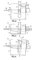
- FIGs. 2 and 3 one possible embodiment is shown having a housing 10 with a fiber holding portion 12 and an optical detector holding portion 14 coupled together by a connecting portion 16 so that there is an interior gap 18 between interior surfaces 20 , 22 .
- An optical detector 24 is mounted in the optical detector holding portion 14 so that its detection surface 26 faces the gap 18 .
- An end of a fiber pigtail 28 is secured by a ferrule 30 in the fiber holding portion 12 such that the end is adjacent to the detection surface 26 in the gap 18 .
- the end of the ferrule 30 and fiber pigtail 28 adjacent to the detection surface 26 is beveled at an angle.
- a means such as a screw 32 through the optical detector holding portion 14 with its tip contacting the interior surface 20 of the fiber holding portion 12 , may be provided to "tilt" the optical detector 24 relative to the end of the ferrule 30 , as shown in Fig. 4, about a point in the connecting portion 16 that is in this instance flexible.
- the ferrule 30 may be rotated slightly to achieve an optimum position, as explained below, with the plane of the bevel being approximately orthogonal to the angle of the tilt. For example if the bevel angle at the end of the ferrule 30 is 20 degrees, based on theoretical calculations and actual empirical data, to achieve essentially zero PDL requires a tilt for the optical detector 24 of about 17.96 degrees, as shown in Fig.
- the rotation may be achieved by rotating the ferrule 30 rather than the detector 24 . Whatever the bevel angle on the ferrule 30 , there is some combination of tilt and rotation (equivalent to rotation of the detector 24) that results in essentially zero PDL. The result is to zero out ( ⁇ 0.001 dB) any polarization-dependent effects in the fiber-pigtailed assembly for the optical detector while having low back reflection ( ⁇ -80 dB).
- the distance of the fiber pigtail 28 from the large-area detector surface 26 is dependent upon the spot size as a function of distance from the end of the fiber pigtail.
- the beveled end of the fiber pigtail should be within about 1.5 mm of the detector surface.
- Adjustment of the fiber-pigtailed optical detector may be achieved by providing, as shown in Fig. 6, a source of different polarization states of light, such as light from a laser source 52 through a polarization scrambler 54 , in a short period of time ( ⁇ 1 sec.) into an external optical fiber 56 .
- the external optical fiber 56 is coupled to the fiber-pigtailed assembly 10 of the optical detector and the electrical output is amplified by an amplifier 58 and displayed on an oscilloscope 60 .
- This provides an electrical signal 62 having a certain peak-to-peak amplitude.
- the ferrule 30 may be rotated to minimize the peak-to-peak amplitude, and then the tilt may be adjusted by the tilt means 32 to further minimize the peak-to-peak amplitude.
- steps may be iterated as necessary to achieve a minimum peak-to-peak amplitude for the electrical signal 62 which represents essentially zero PDL.
- the housing 10 has a fixed tilt angle (based on pre-calculations) between the fiber and detector portions 12, 14 only rotation is adjusted, lessening the adjustment time in the manufacturing of the fiber pigtailed assembly.
- the coupler described here may take the form of a sleeve 40 , as shown in Figs. 7 and 8, having three optical ferrules in series.
- An input ferrule 42 is attached to the end of an external optical fiber 44 of a system to be measured.
- the input ferrule 42 has a beveled end at the end of the external optical fiber 44 .
- An intermediate ferrule 46 contains an optical fiber corresponding to the fiber pigtail 28 and has both ends beveled, with the bevels being in approximately orthogonal planes.
- the intermediate ferrule 46 is placed adjacent the input ferrule 42 so that the adjacent ends are parallel and close, but not necessarily in physical contact.
- an output ferrule 50 is provided on the coupling end of the fiber pigtail 28 adjacent to the intermediate ferrule 46 , and also has a beveled end.
- the output ferrule 50 is placed adjacent to the intermediate ferrule 42 so that the beveled ends are parallel and preferably in physical contact.
- a non-contact coupling is preferred between the external optical fiber 44 and the optical fiber of the intermediate ferrule 46 .
- FIG. 10 shows the residual PDL in the intermediate ferrule 46 when the bevel angle for one pair of interfaces 42/46 is different from the bevel angle of the other pair 46/50.
- the objective is to have approximately 0.1 degree accuracy in maintaining a common bevel angle, such as 7 degrees for this example, and 0.9 degree accuracy in achieving the orthogonal configuration between the interfaces on opposing ends of the intermediate ferrule 46 .
- Coupling the external optical fiber 44 generally a smaller diameter single-mode fiber, to the optical fiber of the intermediate ferrule 46 requires alignment to within about 0.5 mm between the respective fibers based on the spot size from the smaller diameter fiber to the larger.
- the housing 10 has two portions 12, 14 coupled by a connecting portion 16 that may be flexible so that the tilt of the optical detector 26 relative to the beveled end of the fiber ferrule 30 is adjustable
- the housing may be rigid with a fixed angle of tilt for the detector and fiber ferrule based on pre-calculations, as indicated above. In that case only rotation of the fiber ferrule 30 is used to provide adjustment.
- the present invention provides a fiber-pigtailed assembly for an optical detector with minimal back reflection and PDR by having a detector end of an optical fiber with a bevel angle adjacent to the surface of the optical detector, the optical detector being tilted and rotated relative to the end of the optical fiber for both minimum back reflection and PDR, and may include having a coupling end of the optical fiber for the fiber-pigtailed assembly in a coupler having an intermediate ferrule with equal beveled angles on opposing ends situated orthogonally to each other such that they are parallel to respective ends of input and output ferrules of the coupler having matching bevel angles to couple light from an external optical fiber in the input ferrule to the optical fiber in the output ferrule for transmission to the detector.
Landscapes
- Physics & Mathematics (AREA)
- General Physics & Mathematics (AREA)
- Optics & Photonics (AREA)
- Optical Couplings Of Light Guides (AREA)
Abstract
Description

Claims (13)
- A fiber pigtailed assembly for coupling light from an optical fiber to an optical detector comprising means for mounting the optical fiber adjacent to the optical detector, the optical fiber having a beveled end and having a diameter less than the area of a detector surface of the optical detector, so that the light from the beveled end impinges on the detector surface, the detector surface being tilted and rotated with respect to the beveled end to produce essentially zero polarization-dependent responsivity and low back reflection.
- The fiber pigtailed assembly as recited in claim 1 further comprising means for adjusting a tilt angle of the detector surface with respect to the beveled end.
- The fiber pigtailed assembly as recited in claim 1 wherein the mounting means comprises a housing having a fiber holding portion and a detector holding portion coupled together by a connecting portion to form a gap therebetween, the optical fiber being mounted in the fiber holding portion so that the beveled end extends into the gap and the optical detector being mounted in the detector holding portion so that the detector surface is adjacent and tilted and rotated with respect to the beveled end.
- The fiber pigtailed assembly as recited in claim 3 further comprising means for adjusting a tilt angle of the detector surface with respect to the beveled end.
- The fiber pigtailed assembly as recited in claim 4 wherein the adjusting means comprises:the connection portion being flexible; andmeans coupled to the housing for angularly varying the gap to adjust the tilt angle by rotating about a point in the connection portion.
- The fiber pigtailed assembly as recited in claim 5 wherein the angularly varying means comprises a screw threaded through one of the fiber and detector holding portions to contact an opposing surface of the gap such that adjustment of the screw causes the gap to angularly widen.
- The fiber pigtailed assembly as recited in any of claims 1-6 further comprising means for coupling an opposing end of the optical fiber to an external optical fiber with low back reflection and minimum polarization-dependent responsivity.
- The fiber pigtailed assembly as recited in claim 7 wherein the coupling means comprises:an input ferrule containing an end of the external optical fiber, the end being beveled;an intermediate ferrule containing an intermediate optical fiber and having beveled ends arranged approximately orthogonal to each other;an output ferrule containing the opposing end of the optical fiber, the opposing end being beveled; andmeans for holding the input, intermediate and output ferrules in position relative to each other so that the respective beveled ends are parallel to each other.
- The fiber pigtailed assembly as recited in claim 8 wherein the holding means further comprises a gap between the input ferrule and the intermediate ferrule when the diameter of the external optical fiber is less than the diameter of the intermediate optical fiber.
- A coupler for coupling a fiber pigtailed assembly to an external optical fiber with low back reflectance and minimum polarization-dependent responsivity comprising:an input ferrule containing an end of the external optical fiber, the end being beveled;an intermediate ferrule containing an intermediate optical fiber, the intermediate optical fiber having opposing ends that are beveled in approximately orthogonal planes;an output ferrule containing a coupling end of an optical fiber of the fiber pigtailed assembly, the coupling end being beveled; andmeans for holding the input, intermediate and output ferrules in position relative to each other such that the respective beveled ends are parallel to each other.
- The coupler as recited in claim 10 wherein the holding means further comprises a gap between the input ferrule and the intermediate ferrule when the diameter of the external optical fiber is less than the diameter of the intermediate optical fiber.
- A method of adjusting a fiber pigtailed assembly for coupling light from an optical fiber to an optical detector with low back reflectance and minimum polarization-dependent responsivity comprising the steps of:providing a source of light having a plurality of polarization states to the optical fiber;adjusting a rotation angle between a beveled end of the optical fiber and a detector surface of the optical detector adjacent the beveled end, the detector surface being tilted with respect to the beveled end, while observing an electrical output from the optical detector for a minimum peak-to-peak value.
- The method as recited in claim 12 further comprising the steps of:adjusting a tilt angle between the detector surface and the beveled end while observing the electrical output from the optical detector for the minimum peak-to-peak value; anditerating the rotation and tilt angle adjusting steps as necessary to obtain the lowest minimum peak-to-peak value for the electrical output.
Applications Claiming Priority (2)
| Application Number | Priority Date | Filing Date | Title |
|---|---|---|---|
| US10/058,585 US6789955B2 (en) | 2002-01-24 | 2002-01-24 | Fiber-pigtailed assembly |
| US58585 | 2002-01-24 |
Publications (2)
| Publication Number | Publication Date |
|---|---|
| EP1331500A2 true EP1331500A2 (en) | 2003-07-30 |
| EP1331500A3 EP1331500A3 (en) | 2004-10-13 |
Family
ID=22017737
Family Applications (1)
| Application Number | Title | Priority Date | Filing Date |
|---|---|---|---|
| EP03250188A Withdrawn EP1331500A3 (en) | 2002-01-24 | 2003-01-13 | Fiber-pigtailed assembly |
Country Status (3)
| Country | Link |
|---|---|
| US (2) | US6789955B2 (en) |
| EP (1) | EP1331500A3 (en) |
| JP (1) | JP2003232964A (en) |
Cited By (1)
| Publication number | Priority date | Publication date | Assignee | Title |
|---|---|---|---|---|
| EP3168661A4 (en) * | 2014-07-07 | 2017-11-22 | Shanghai Institute of Optics and Fine Mechanics Chinese Academy of Sciences | Hollow-core photonic crystal fiber gas cell and manufacturing method therefor |
Families Citing this family (15)
| Publication number | Priority date | Publication date | Assignee | Title |
|---|---|---|---|---|
| AU5948499A (en) | 1998-03-05 | 1999-11-29 | Victor Spivak | Optical-acoustic imaging device |
| SE516862C2 (en) * | 2000-07-14 | 2002-03-12 | Allgon Ab | Reconciliation screw device and method and resonator |
| US7245789B2 (en) | 2002-10-07 | 2007-07-17 | Vascular Imaging Corporation | Systems and methods for minimally-invasive optical-acoustic imaging |
| US7354201B2 (en) * | 2002-11-26 | 2008-04-08 | Finisar Corporation | Devices for reflection reduction in optical devices |
| US6925234B2 (en) * | 2002-12-12 | 2005-08-02 | Melles Griot, Inc. | Flexure apparatus and method for achieving efficient optical coupling |
| US7599588B2 (en) | 2005-11-22 | 2009-10-06 | Vascular Imaging Corporation | Optical imaging probe connector |
| US20100096538A1 (en) * | 2006-09-28 | 2010-04-22 | Jin-Sang Hwang | Method for measuring angular displacement using optical fiber and method for manufacturing the same |
| WO2010039950A1 (en) | 2008-10-02 | 2010-04-08 | Eberle Michael J | Optical ultrasound receiver |
| EP2417484B1 (en) | 2008-10-31 | 2014-12-31 | Vascular Imaging Corporation | Optical imaging probe connector |
| US9366938B1 (en) | 2009-02-17 | 2016-06-14 | Vescent Photonics, Inc. | Electro-optic beam deflector device |
| DE102010041689B4 (en) * | 2010-09-29 | 2021-04-22 | Lasos Lasertechnik Gmbh | Socket for receiving a plug with a light guide |
| JP2012234035A (en) * | 2011-04-28 | 2012-11-29 | Toshiba Corp | Optical coupling element and method for fixing the same |
| US20140016897A1 (en) * | 2011-08-16 | 2014-01-16 | TeraDiode, Inc. | Adjustable Fiber Optic Module System and Method |
| JP6236912B2 (en) * | 2013-06-24 | 2017-11-29 | 住友電気工業株式会社 | Optical receiver and optical axis alignment method thereof |
| CN107272125B (en) * | 2017-07-28 | 2019-01-29 | 重庆大学 | An optomechanical adjustment device for precise alignment of optical paths based on magnetic connection |
Family Cites Families (11)
| Publication number | Priority date | Publication date | Assignee | Title |
|---|---|---|---|---|
| US4165496A (en) * | 1977-12-16 | 1979-08-21 | Bell Telephone Laboratories, Incorporated | Optical fiber light tap |
| US4930858A (en) * | 1988-05-09 | 1990-06-05 | Tektronix, Inc. | Fiber optic mounting and alignment apparatus |
| DE4217806A1 (en) * | 1992-05-29 | 1993-12-16 | Hirschmann Richard Gmbh Co | Optical coupler |
| US5282259A (en) * | 1992-11-16 | 1994-01-25 | Molex Incorporated | Optical fiber alignment device |
| JP3208996B2 (en) * | 1994-05-20 | 2001-09-17 | 安藤電気株式会社 | Light receiving method and light receiving module with little polarization dependence |
| JP2882328B2 (en) * | 1995-12-15 | 1999-04-12 | 日本電気株式会社 | Low polarization dependent optical fiber connection structure |
| WO1997032344A1 (en) * | 1996-02-28 | 1997-09-04 | The Whitaker Corporation | Packaging for optoelectronic device |
| GB2311146A (en) * | 1996-03-14 | 1997-09-17 | Integrated Optical Components | Aligning birefringent optical fibre using polarising probe |
| JP3824797B2 (en) * | 1999-01-08 | 2006-09-20 | 古河電気工業株式会社 | Light emitting / receiving element module |
| EP1059543A1 (en) * | 1999-05-12 | 2000-12-13 | Hewlett-Packard Company | Measuring device with an optical interface with low polarization dependent loss (PDL) |
| US6621067B2 (en) * | 2000-03-03 | 2003-09-16 | Exfo Electro-Optical Engineering Inc. | Polarization independent photodetector device and method of making same |
-
2002
- 2002-01-24 US US10/058,585 patent/US6789955B2/en not_active Expired - Fee Related
-
2003
- 2003-01-13 EP EP03250188A patent/EP1331500A3/en not_active Withdrawn
- 2003-01-23 JP JP2003014425A patent/JP2003232964A/en active Pending
- 2003-07-02 US US10/613,562 patent/US6948859B2/en not_active Expired - Lifetime
Cited By (1)
| Publication number | Priority date | Publication date | Assignee | Title |
|---|---|---|---|---|
| EP3168661A4 (en) * | 2014-07-07 | 2017-11-22 | Shanghai Institute of Optics and Fine Mechanics Chinese Academy of Sciences | Hollow-core photonic crystal fiber gas cell and manufacturing method therefor |
Also Published As
| Publication number | Publication date |
|---|---|
| US6789955B2 (en) | 2004-09-14 |
| US20040005125A1 (en) | 2004-01-08 |
| US20030138218A1 (en) | 2003-07-24 |
| EP1331500A3 (en) | 2004-10-13 |
| JP2003232964A (en) | 2003-08-22 |
| US6948859B2 (en) | 2005-09-27 |
Similar Documents
| Publication | Publication Date | Title |
|---|---|---|
| US6789955B2 (en) | Fiber-pigtailed assembly | |
| US4893889A (en) | Optical attenuator | |
| US4893890A (en) | Low-loss, high-isolation, fiber-optic isolator | |
| JP3112198B2 (en) | Gradient index lens and optical receiver | |
| US8760653B2 (en) | Assembly for monitoring power of randomly polarized light | |
| US6842467B1 (en) | Fiber optic laser transmitter with reduced near end reflections | |
| US6434176B1 (en) | Frequency stabilized laser system | |
| US5471306A (en) | Method for assembling optical isolator and method for measuring isolation | |
| EP1498690B1 (en) | Thickness measuring device | |
| US5734667A (en) | Polarization-stable laser | |
| Mutugala et al. | All-fiber passive alignment-free depolarizers capable of depolarizing narrow linewidth signals | |
| Scholl et al. | In-line fiber optic polarimeter with a 99% coupler | |
| US6430338B1 (en) | Measuring device with an optical interface with low polarization dependent loss (PDL) | |
| JPH04268515A (en) | Device for connecting polarization maintaining optical fiber | |
| JPH04268517A (en) | Connection device for polarization holding optical fiber | |
| KR20000049227A (en) | Apparatus with a retracing optical circuit for the measurement of physical quantities having high rejection of environmental noise | |
| JPS6157745B2 (en) | ||
| Masuda et al. | Polarization-preserving fiber-optic 2X2 directional coupler | |
| JP3001868U (en) | Polarization fluctuation measuring device | |
| JP2000068602A (en) | Optical amplification gain measuring device | |
| Masuda et al. | Polarization preserving fiber-optic 2X2 directional coupler (PPFDC) | |
| CN112630899A (en) | Detachable sealed laser polarization-maintaining transmission device | |
| Wesson et al. | Fiber optic splice loss measurement | |
| Challans et al. | Expanded-beam singlemode connector | |
| Braun et al. | Precision Reflectometer with Spurious-Free Enhanced Sensitivity |
Legal Events
| Date | Code | Title | Description |
|---|---|---|---|
| PUAI | Public reference made under article 153(3) epc to a published international application that has entered the european phase |
Free format text: ORIGINAL CODE: 0009012 |
|
| AK | Designated contracting states |
Designated state(s): AT BE BG CH CY CZ DE DK EE ES FI FR GB GR HU IE IT LI LU MC NL PT SE SI SK TR |
|
| AX | Request for extension of the european patent |
Extension state: AL LT LV MK RO |
|
| PUAL | Search report despatched |
Free format text: ORIGINAL CODE: 0009013 |
|
| AK | Designated contracting states |
Kind code of ref document: A3 Designated state(s): AT BE BG CH CY CZ DE DK EE ES FI FR GB GR HU IE IT LI LU MC NL PT SE SI SK TR |
|
| AX | Request for extension of the european patent |
Extension state: AL LT LV MK RO |
|
| RIC1 | Information provided on ipc code assigned before grant |
Ipc: 7G 02B 6/26 B Ipc: 7G 02B 6/42 A |
|
| 17P | Request for examination filed |
Effective date: 20050404 |
|
| AKX | Designation fees paid |
Designated state(s): DE FR GB IT |
|
| 17Q | First examination report despatched |
Effective date: 20050721 |
|
| STAA | Information on the status of an ep patent application or granted ep patent |
Free format text: STATUS: THE APPLICATION IS DEEMED TO BE WITHDRAWN |
|
| 18D | Application deemed to be withdrawn |
Effective date: 20061201 |