EP1331392A2 - System and method for controlling shape memory alloy actuators - Google Patents
System and method for controlling shape memory alloy actuators Download PDFInfo
- Publication number
- EP1331392A2 EP1331392A2 EP03250473A EP03250473A EP1331392A2 EP 1331392 A2 EP1331392 A2 EP 1331392A2 EP 03250473 A EP03250473 A EP 03250473A EP 03250473 A EP03250473 A EP 03250473A EP 1331392 A2 EP1331392 A2 EP 1331392A2
- Authority
- EP
- European Patent Office
- Prior art keywords
- sma actuator
- voltage
- target position
- sma
- actuator
- Prior art date
- Legal status (The legal status is an assumption and is not a legal conclusion. Google has not performed a legal analysis and makes no representation as to the accuracy of the status listed.)
- Granted
Links
Images


Classifications
-
- F—MECHANICAL ENGINEERING; LIGHTING; HEATING; WEAPONS; BLASTING
- F03—MACHINES OR ENGINES FOR LIQUIDS; WIND, SPRING, OR WEIGHT MOTORS; PRODUCING MECHANICAL POWER OR A REACTIVE PROPULSIVE THRUST, NOT OTHERWISE PROVIDED FOR
- F03G—SPRING, WEIGHT, INERTIA OR LIKE MOTORS; MECHANICAL-POWER PRODUCING DEVICES OR MECHANISMS, NOT OTHERWISE PROVIDED FOR OR USING ENERGY SOURCES NOT OTHERWISE PROVIDED FOR
- F03G7/00—Mechanical-power-producing mechanisms, not otherwise provided for or using energy sources not otherwise provided for
- F03G7/06—Mechanical-power-producing mechanisms, not otherwise provided for or using energy sources not otherwise provided for using expansion or contraction of bodies due to heating, cooling, moistening, drying or the like
- F03G7/061—Mechanical-power-producing mechanisms, not otherwise provided for or using energy sources not otherwise provided for using expansion or contraction of bodies due to heating, cooling, moistening, drying or the like characterised by the actuating element
- F03G7/0614—Mechanical-power-producing mechanisms, not otherwise provided for or using energy sources not otherwise provided for using expansion or contraction of bodies due to heating, cooling, moistening, drying or the like characterised by the actuating element using shape memory elements
- F03G7/06143—Wires
-
- F—MECHANICAL ENGINEERING; LIGHTING; HEATING; WEAPONS; BLASTING
- F03—MACHINES OR ENGINES FOR LIQUIDS; WIND, SPRING, OR WEIGHT MOTORS; PRODUCING MECHANICAL POWER OR A REACTIVE PROPULSIVE THRUST, NOT OTHERWISE PROVIDED FOR
- F03G—SPRING, WEIGHT, INERTIA OR LIKE MOTORS; MECHANICAL-POWER PRODUCING DEVICES OR MECHANISMS, NOT OTHERWISE PROVIDED FOR OR USING ENERGY SOURCES NOT OTHERWISE PROVIDED FOR
- F03G7/00—Mechanical-power-producing mechanisms, not otherwise provided for or using energy sources not otherwise provided for
- F03G7/06—Mechanical-power-producing mechanisms, not otherwise provided for or using energy sources not otherwise provided for using expansion or contraction of bodies due to heating, cooling, moistening, drying or the like
- F03G7/066—Actuator control or monitoring
Definitions
- This invention relates generally to control systems, and more specifically to a system and method of controlling shape memory alloy actuators.
- Shape memory alloy (SMA) actuators have the potential for use in a wide range of actuator applications including space stations, automotive components, surgical devices and robotic arms.
- SMA actuators are described more fully in U.S. Patent No. 6,318,070 B1 issued on November 20, 2002 and entitled “Variable Area Nozzle For Gas Turbine Engines Driven By Shape Memory Alloy Actuators”; U.S. Published Patent Application Serial No. US 2002 0073691 A1 and entitled “Variable Area Nozzle For Gas Turbine Engines Driven By Shape Memory Alloy Actuators”; and U.S. Patent Application Serial No. 09/517,938 filed March 3, 2000 and entitled “Shape Memory Alloy Bundles And Actuators", the disclosures of which are herein incorporated by reference.
- Resistive heating is used as the means to induce martensite to austenite transformation in the material, which produces recovery stress. This stress can be used for actuation.
- This stress can be used for actuation.
- the required temperature and hence the required amount of stress can be achieved. Since the power requirements may vary subject to such unknowns as ambient temperature, hysteresis and material degradation, open loop control (i.e., supplying predetermined power for a specific desired position) does not work; one has to resort to closed loop feedback control.
- a closed loop feedback control system is required to achieve this objective.
- the challenge in devising an effective control algorithm for such a position control system is the nonlinear hysteretic behavior of SMA, which renders conventional linear control laws such as proportional integral derivative (PID) less effective.
- Conventional (PID type) SMA controllers have been applied to thin SMA wires. Because of the small size of the SMA wires, and therefore the consequent fast heating/ cooling behavior of the wires, PID can be employed with reasonable success.
- a large bundled cable actuator such as, for example, an actuator having 266 wires of 0.02" (0.508 mm) diameter each, cannot be controlled by conventional PID type feedback control.
- a powerful control approach is to employ a mathematical model of the hysteresis behavior of shape memory material to determine the control action. Since material property is subject to change over time, such models need to be updated continuously through real-time measurements and adaptive algorithms. A drawback with such an approach is that it is complex and computationally intensive, and consequently time consuming and expensive to implement.
- a method of controlling a shape memory alloy (SMA) actuator comprises the steps of supplying maximum control voltage to an SMA actuator where an object having a position to be controlled by the SMA actuator were to move toward a target position upon supply of non-zero control voltage, and the instantaneous actual position of the object is at a distance above a predetermined threshold from the target position.
- a variably controlled voltage is supplied to the SMA actuator between the maximum voltage and about zero voltage where the object to be controlled were to move toward the target position upon supply of the variably controlled voltage, and the instantaneous actual position of the object is at a distance below the predetermined threshold from the target position.
- a method of controlling an SMA actuator comprises the steps of providing an SMA actuator for moving an object to a predetermined target position.
- a maximum control voltage is supplied to the SMA actuator where an object having a position to be controlled by the SMA actuator were to move toward a target position upon supply of non-zero control voltage, and the instantaneous actual position of the object is at a distance above a predetermined threshold from the target position.
- a variably controlled voltage is supplied to the SMA actuator between the maximum voltage and about zero voltage where the object to be controlled were to move toward the target position upon supply of the variably controlled voltage, and the instantaneous actual position of the object is at a distance below the predetermined threshold from the target position.
- an SMA actuator control system comprises an SMA actuator including SMA wires and at least one position sensor.
- the SMA actuator is to be coupled to an object having a position to be moved by the SMA actuator.
- the system includes means for supplying maximum control voltage to the SMA actuator where the object having a position to be controlled by the SMA actuator were to move toward a target position upon supply of a non-zero control voltage, and the instantaneous actual position of the object is at a distance above a predetermined threshold from the target position.
- the system further includes means for supplying a variably controlled voltage to the SMA actuator between the maximum voltage and about zero voltage where the object to be controlled were to move toward the target position upon supply of the variably controlled voltage, and the instantaneous actual position of the object is at a distance below the predetermined threshold from the target position.
- An advantage of the present invention in its preferred embodiments is that the power to the SMA actuator is cut off prior to the controlled object reaching the target position so as to prevent overshoot of the target position.
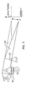
- a system and method in accordance with the present invention for controlling an SMA actuator is illustrated by means of a combination structure/flow diagram as shown in FIG. 1 and a structural diagram shown in FIG. 2.
- the system and method is explained with reference to an SMA system 10 having a control processor 12, an SMA actuator 14 including SMA wires or cables, a power supply 16 and position sensors 18.
- SMA system 10 having a control processor 12, an SMA actuator 14 including SMA wires or cables, a power supply 16 and position sensors 18.
- other actuators may be substituted and other applications used without departing from the scope of the present invention.
- any application where shape memory effect is used to produce a measurable output e.g., displacement of an end effector
- the processor 12 has an input coupled to the position sensors 18, and an output coupled to the power supply 16 for sending a control command voltage V c to the power supply, which in turn, supplies a voltage V SMA and corresponding current to the SMA cables of the SMA actuator 14 as a function of the position of the object measured by the position sensors 18.
- the actual voltage V SMA across the SMA as supplied by the power supply 16 is proportional to the control voltage V c .
- V SMA 8*V c , but may be a different proportion depending on the type of power supply.
- the control law is, however, independent of the specific constant of proportionality.
- the SMA actuator system 10 shown by way of example in FIG. 2 controls the position of point A of a mechanical linkage 20 in the presence of load M (hinge moment) by metering (i.e., variably controlling) the heat supplied to the SMA actuator 14.
- the SMA actuator 14 is initially strained in the base state. Once heated, recovery stress is developed which is used for actuation of the linkage 20.
- a control input is the voltage V SMA to the SMA actuator 100, and the output of the actuator is the position x of point A.
- Point A of the mechanical linkage 20 is to be moved to a predetermined position x d in the smallest amount of time with minimum error.
- the position x is so defined that the initial position is larger in value than that of the target position.
- Terminology to be used in explaining control of the SMA actuator 14 by the system and method in accordance with the present invention is as follows:
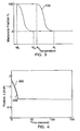
- the current supplied to the SMA wires 16 should be reduced intelligently, and should be cut off before the target is reached by the end effector, otherwise the temperature of the SMA wires continues to increase for a short time even after the current has been cut off (thermal inertia), and the desired position is overshot. If the end effector overshoots the desired position, it takes a long time to cool and come back to that position due to hysteresis in the SMA strain vs. temperature characteristics, as shown by the hysteresis curve 100 in FIG. 3.
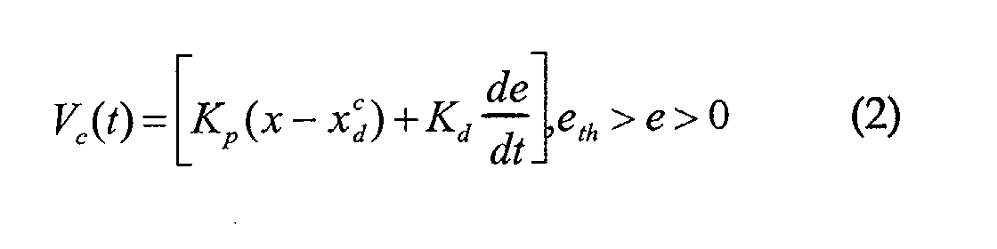
- the control law is similar to a PI (proportional-integral) controller, except that the proportional part is not proportional to the measured error x-x d , but to a fictitious error x - x c / d .
- the value of x c / d is updated by the estimation law in the fourth equation. The logic is that if x is less than x d , x c / d should decrease, but otherwise should remain constant. Dickinson and Wen had first suggested this way of adaptation. However, in their method, the adaptation was not turned off when error became negative. In accordance with the preferred embodiments of the present invention, it is always kept on. Moreover, their control method did not include the derivative term. It has been discovered that the derivative term reduces the overshoot error by decreasing the control input when the error is decreasing fast.
- the bundled cable SMA actuator 14 is used to move the mechanical linkage 20 hinged at one end 22 while an opposing load is applied with a pneumatic piston-cylinder assembly.
- the operation includes commanding the tip A of the mechanical linkage 20 to move to a specified target position x d .
- the metrics of performance of the controller are how fast point "A" of the mechanical linkage 20 reaches the target position x d with how little overshoot and how well the position is maintained once it is reached.
- Constant air pressure is applied to maintain constant load throughout the operation.
- the SMA wires 14 are preheated to, for example, 80° F (26.6°C) prior to commencing the operation. As shown in FIG.
- FIG. 4 also shows a curve 300 indicative of the performance of a conventional PID controller.
- the gains of the PID controller are tuned for this particular case. It is seen that the method in accordance with the present invention performs comparably to the PID. However, its strength lies in its robustness which is demonstrated in FIG. 5.
- FIG. 5 compares the performance of the control method embodying the present invention in a step-input test for two very different sets of gains.
- the first set of values are the well-tuned gains derived from previous tests, whereas in the second set, the exponent ⁇ is made larger.
- the values t tr , e th etc. are kept the same for both cases.
- Curve 400 is indicative of the instantaneous actual position x as a function of time for case 1
- curve 500 is indicative of the instantaneous actual position x as a function of time for case 2. It is readily seen from FIG. 5 that the curves 400 and 500 generally overlap and are indistinguishable from one another, thus indicating that the controller works equally well in these cases though the gains are different. This shows that the controller performance is less sensitive to the gains. The low sensitivity of performance to tuning is due to the logic checks in the control method embodying the present invention.
Landscapes
- Engineering & Computer Science (AREA)
- Chemical & Material Sciences (AREA)
- Combustion & Propulsion (AREA)
- Mechanical Engineering (AREA)
- General Engineering & Computer Science (AREA)
- Control Of Position Or Direction (AREA)
- Feedback Control In General (AREA)
Abstract
Description
Claims (9)
- A method of controlling a shape memory alloy (SMA) actuator (14), comprising the steps of:supplying maximum control voltage (VCmax) to an SMA actuator (14) where an object having a position to be controlled by the SMA actuator were to move toward a target position (xd) upon supply of non-zero control voltage, and the instantaneous actual position (x) of the object is at a distance above a predetermined threshold from the target position; andsupplying a variably controlled voltage (Vc) to the SMA actuator (14) between the maximum voltage (VCmax) and about zero voltage where the object to be controlled were to move toward the target position upon supply of the variably controlled voltage, and the instantaneous actual position (x) of the object is at a distance below the predetermined threshold from the target position.
- A method of controlling a shape memory alloy (SMA) actuator (14) as claimed in claim 1
providing an SMA actuator (14) for moving an object to a predetermined target position (xd). - A method of controlling an SMA actuator (14) as defined in claims 1 or 2, further including the step of:supplying a control voltage (Vc) of about zero volts to the SMA actuator (14) where the object having a position to be controlled by the SMA actuator were to move away from the target position (xd) upon supply of a non-zero control voltage.
- A method of controlling an SMA actuator (14) as defined in any preceding claim, wherein the step of supplying a variably controlled voltage (VC) is defined by the equation:

- A method of controlling an SMA actuator (14) as defined in any preceding claim, further including the steps of:periodically predicting a time (th) to reach the target position (xd); andcutting off current to the SMA actuator (14) when the time (th) to reach the target position (xd) is smaller than a predetermined threshold value (ttr), and the instantaneous actual position (x) is at a distance below a low threshold value from the target position.
- An SMA actuator control system (10) comprising:an SMA actuator (14) including SMA wires (16) and at least one position sensor (18), the SMA actuator to be coupled to an object having a position to be moved by the SMA actuator;means (12) for supplying maximum control voltage (VCmax) to the SMA actuator (14) where the object having a position to be controlled by the SMA actuator were to move toward a target position (xd) upon supply of a non-zero control voltage, and the instantaneous actual position (x) of the object is at a distance above a predetermined threshold from the target position; andmeans (12) for supplying a variably controlled voltage (VC) to the SMA actuator (14) between the maximum voltage (VCmax) and about zero voltage where the object to be controlled were to move toward the target position (xd) upon supply of the variably controlled voltage, and the instantaneous actual position (x) of the object is at a distance below the predetermined threshold from the target position.
- An SMA actuator control system (10) as defined in claim 6, further including means (12) for supplying a control voltage (VC) of about zero volts to the SMA actuator (14) where the object having a position to be controlled by the SMA actuator were to move away from the target position (xd) upon supply of non-zero control voltage.
- An SMA actuator control system (10) as defined in claim 6 or 7, wherein the means (12) for supplying a variably controlled voltage (VC) generates the voltage in accordance with the equation:

- An SMA actuator control system (10) as defined in claims 6, 7 or 8, further including:means (12) for periodically predicting a time (th) to reach the target position (xd); andmeans (12) for cutting off current to the SMA actuator (14) when the time (th) to reach the target position (xd) is smaller than a predetermined threshold value (ttr), and the instantaneous actual position (x) is at a distance below a low threshold value from the target position.
Applications Claiming Priority (2)
| Application Number | Priority Date | Filing Date | Title |
|---|---|---|---|
| US10/059,880 US6543224B1 (en) | 2002-01-29 | 2002-01-29 | System and method for controlling shape memory alloy actuators |
| US59880 | 2002-01-29 |
Publications (3)
| Publication Number | Publication Date |
|---|---|
| EP1331392A2 true EP1331392A2 (en) | 2003-07-30 |
| EP1331392A3 EP1331392A3 (en) | 2005-09-07 |
| EP1331392B1 EP1331392B1 (en) | 2008-07-23 |
Family
ID=22025884
Family Applications (1)
| Application Number | Title | Priority Date | Filing Date |
|---|---|---|---|
| EP03250473A Expired - Lifetime EP1331392B1 (en) | 2002-01-29 | 2003-01-27 | System and method for controlling shape memory alloy actuators |
Country Status (4)
| Country | Link |
|---|---|
| US (1) | US6543224B1 (en) |
| EP (1) | EP1331392B1 (en) |
| JP (1) | JP2003227458A (en) |
| DE (1) | DE60322280D1 (en) |
Cited By (1)
| Publication number | Priority date | Publication date | Assignee | Title |
|---|---|---|---|---|
| WO2009114357A3 (en) * | 2008-03-07 | 2009-12-10 | Gm Global Technology Operations, Inc. | Shape memory alloy cables |
Families Citing this family (38)
| Publication number | Priority date | Publication date | Assignee | Title |
|---|---|---|---|---|
| US6969920B1 (en) * | 2002-06-07 | 2005-11-29 | Mondo-Tronics | Low current shape memory alloy devices |
| US7727181B2 (en) | 2002-10-09 | 2010-06-01 | Abbott Diabetes Care Inc. | Fluid delivery device with autocalibration |
| US7993108B2 (en) * | 2002-10-09 | 2011-08-09 | Abbott Diabetes Care Inc. | Variable volume, shape memory actuated insulin dispensing pump |
| CA2501825C (en) | 2002-10-09 | 2009-12-01 | Therasense, Inc. | Fluid delivery device, system and method |
| US7240677B2 (en) * | 2003-02-03 | 2007-07-10 | Biomedical Enterprises, Inc. | System and method for force, displacement, and rate control of shaped memory material implants |
| KR20060005403A (en) * | 2003-04-28 | 2006-01-17 | 나노머슬, 인크. | Flow control assembly with integrally formed shape memory alloy actuator |
| US7679407B2 (en) | 2003-04-28 | 2010-03-16 | Abbott Diabetes Care Inc. | Method and apparatus for providing peak detection circuitry for data communication systems |
| WO2005026539A2 (en) * | 2003-09-05 | 2005-03-24 | Alfmeier Präzision | Apparatus and method for low cost control of shape memory alloy actuators |
| WO2005026592A2 (en) * | 2003-09-05 | 2005-03-24 | Alfmeier Präzision AG Baugruppen und Systemlösungen | A system, method and apparatus for reducing frictional forces and for compensating shape memory alloy-actuated valves and valve systems at high temperatures |
| US7340883B2 (en) | 2004-11-12 | 2008-03-11 | The Boeing Company | Morphing structure |
| JP4301153B2 (en) * | 2004-11-29 | 2009-07-22 | コニカミノルタホールディングス株式会社 | Manufacturing unit and manufacturing method of position control device |
| JP4553725B2 (en) * | 2004-12-27 | 2010-09-29 | トキコーポレーション株式会社 | Actuator |
| US7647771B2 (en) * | 2005-03-09 | 2010-01-19 | The United States Of America As Represented By The Administrator Of The National Aeronautics And Space Administration | Thermally driven piston assembly and position control therefor |
| CN101180093B (en) * | 2005-03-21 | 2012-07-18 | 雅培糖尿病护理公司 | Method and system for providing integrated medication infusion and analyte monitoring system |
| US7768408B2 (en) | 2005-05-17 | 2010-08-03 | Abbott Diabetes Care Inc. | Method and system for providing data management in data monitoring system |
| US7620437B2 (en) | 2005-06-03 | 2009-11-17 | Abbott Diabetes Care Inc. | Method and apparatus for providing rechargeable power in data monitoring and management systems |
| US7583190B2 (en) | 2005-10-31 | 2009-09-01 | Abbott Diabetes Care Inc. | Method and apparatus for providing data communication in data monitoring and management systems |
| US20070243073A1 (en) * | 2006-03-08 | 2007-10-18 | U.S.A. As Represented By The Administrator Of The National Aeronautics And Space Administration | Thermally Driven Piston Assembly And Position Control Therefor |
| US7762078B2 (en) * | 2006-09-13 | 2010-07-27 | Aerojet-General Corporation | Nozzle with temperature-responsive throat diameter |
| US7254997B1 (en) | 2006-10-12 | 2007-08-14 | David Hui | Anti-steal tire pressure monitoring apparatus |
| US8579853B2 (en) | 2006-10-31 | 2013-11-12 | Abbott Diabetes Care Inc. | Infusion devices and methods |
| US7721549B2 (en) * | 2007-02-08 | 2010-05-25 | United Technologies Corporation | Fan variable area nozzle for a gas turbine engine fan nacelle with cam drive ring actuation system |
| US7966827B2 (en) * | 2007-05-31 | 2011-06-28 | United Technologies Corporation | Gas turbine engine with fan variable area nozzle having a rotational valve system |
| US8448434B2 (en) * | 2007-11-12 | 2013-05-28 | Konica Minolta Opto, Inc. | Shape memory alloy drive device |
| CN101910903B (en) * | 2008-01-15 | 2013-08-07 | 柯尼卡美能达精密光学株式会社 | Driving device made of shape-memory alloy |
| CA2714496C (en) * | 2008-02-21 | 2017-07-18 | Canadian Space Agency | Feedback control for shape memory alloy actuators |
| US7716932B2 (en) * | 2008-07-24 | 2010-05-18 | Spirit Aerosystems, Inc. | Dilating fan duct nozzle |
| JP2010048120A (en) * | 2008-08-20 | 2010-03-04 | Olympus Corp | Shape memory alloy actuator system |
| US8560082B2 (en) | 2009-01-30 | 2013-10-15 | Abbott Diabetes Care Inc. | Computerized determination of insulin pump therapy parameters using real time and retrospective data processing |
| US8467972B2 (en) | 2009-04-28 | 2013-06-18 | Abbott Diabetes Care Inc. | Closed loop blood glucose control algorithm analysis |
| US8390305B2 (en) * | 2009-05-08 | 2013-03-05 | GM Global Technology Operations LLC | Methods of determining mid-stroke positions of active material actuated loads |
| DK3173014T4 (en) | 2009-07-23 | 2026-03-30 | Abbott Diabetes Care Inc | Real-time management of data regarding physiological control of glucose levels |
| US8584456B1 (en) | 2010-05-21 | 2013-11-19 | Hrl Laboratories, Llc | Bistable actuator mechanism |
| US8549834B2 (en) | 2010-10-21 | 2013-10-08 | United Technologies Corporation | Gas turbine engine with variable area fan nozzle |
| DE102012020310B4 (en) * | 2012-10-16 | 2014-05-22 | Fraunhofer-Gesellschaft zur Förderung der angewandten Forschung e.V. | Method for position control of an actuator, actuator and computer program storage medium |
| US9488130B2 (en) | 2013-10-17 | 2016-11-08 | Honeywell International Inc. | Variable area fan nozzle systems with improved drive couplings |
| GB201511487D0 (en) * | 2015-06-30 | 2015-08-12 | Exergyn Ltd | Method and system for efficiency increase in an energy recovery device |
| CN114562435B (en) * | 2016-09-14 | 2025-10-28 | 智能合金有限公司 | Shape memory alloy actuator with strain gauge sensor and position estimation and method of manufacturing the same |
Family Cites Families (7)
| Publication number | Priority date | Publication date | Assignee | Title |
|---|---|---|---|---|
| BE526525A (en) * | 1953-02-16 | |||
| US4559512A (en) * | 1983-03-14 | 1985-12-17 | Raychem Corporation | Self-protecting and conditioning memory metal actuator |
| US5270643A (en) * | 1990-11-28 | 1993-12-14 | Schlumberger Technologies | Pulsed laser photoemission electron-beam probe |
| US5226619A (en) * | 1991-10-15 | 1993-07-13 | Alger Robert E | Actuator mechanism |
| JPH07237599A (en) * | 1994-03-02 | 1995-09-12 | Natl Space Dev Agency Japan<Nasda> | Shape memory alloy actuator for space equipment |
| US6019113A (en) * | 1998-10-26 | 2000-02-01 | General Motors Corporation | Method and apparatus for controlling a shape memory alloy fuel injector |
| US6318070B1 (en) | 2000-03-03 | 2001-11-20 | United Technologies Corporation | Variable area nozzle for gas turbine engines driven by shape memory alloy actuators |
-
2002
- 2002-01-29 US US10/059,880 patent/US6543224B1/en not_active Expired - Lifetime
-
2003
- 2003-01-27 DE DE60322280T patent/DE60322280D1/en not_active Expired - Lifetime
- 2003-01-27 EP EP03250473A patent/EP1331392B1/en not_active Expired - Lifetime
- 2003-01-28 JP JP2003018198A patent/JP2003227458A/en active Pending
Cited By (1)
| Publication number | Priority date | Publication date | Assignee | Title |
|---|---|---|---|---|
| WO2009114357A3 (en) * | 2008-03-07 | 2009-12-10 | Gm Global Technology Operations, Inc. | Shape memory alloy cables |
Also Published As
| Publication number | Publication date |
|---|---|
| JP2003227458A (en) | 2003-08-15 |
| DE60322280D1 (en) | 2008-09-04 |
| EP1331392B1 (en) | 2008-07-23 |
| US6543224B1 (en) | 2003-04-08 |
| EP1331392A3 (en) | 2005-09-07 |
Similar Documents
| Publication | Publication Date | Title |
|---|---|---|
| US6543224B1 (en) | System and method for controlling shape memory alloy actuators | |
| US6686716B1 (en) | Tuned open-loop switched to closed-loop method for rapid point-to-point movement of a periodic motion control system | |
| EP1707757B1 (en) | Turbine starting controller and turbine starting control method | |
| US8136356B2 (en) | Shape memory alloy actuator system | |
| US9738023B2 (en) | Adaptive control device and adaptive control method, and control device and control method for injection molding machine | |
| EP0604149B1 (en) | Apparatus for controlling the position of a control member | |
| EP1196833B1 (en) | System and method for a variable gain proportional-integral (pi) controller | |
| US7886535B2 (en) | Position control method for shape memory alloy actuator | |
| US8666556B2 (en) | Systems and methods for dynamic feedforward | |
| US20100045214A1 (en) | Shape memory alloy actuator system | |
| Kumagai et al. | Neurofuzzy-model-based feedback controller for shape memory alloy actuators | |
| US7250738B1 (en) | Nonlinear hysteresis control system | |
| US5666810A (en) | Electro-thermal actuator system | |
| US6647318B2 (en) | Pulse modulation adaptive control method for activating an electrical device | |
| US6523522B1 (en) | Method and apparatus for operating a throttle plate motor driving a throttle plate having opposing return springs | |
| Song et al. | Control of shape memory alloy actuators using pulse-width pulse-frequency (PWPF) modulation | |
| US20040148059A1 (en) | Limit cycle autotuning method and heat/cool control apparatus | |
| US6378493B1 (en) | Throttle position control system | |
| JP4036520B2 (en) | Simple adaptive controller | |
| US12234811B1 (en) | Monitoring a state of a shape memory material member | |
| JPH0772927A (en) | Shape memory alloy actuator controller | |
| KR20190083750A (en) | Gear actuator control method and apparatus | |
| Pereira et al. | Adaptive RBFNN versus self-tuning controller: An experimental comparative study | |
| CN116027542B (en) | A laser brightness adjustment method for laser focusing | |
| GB2630127A (en) | Driving of an SMA acuator |
Legal Events
| Date | Code | Title | Description |
|---|---|---|---|
| PUAI | Public reference made under article 153(3) epc to a published international application that has entered the european phase |
Free format text: ORIGINAL CODE: 0009012 |
|
| AK | Designated contracting states |
Designated state(s): AT BE BG CH CY CZ DE DK EE ES FI FR GB GR HU IE IT LI LU MC NL PT SE SI SK TR |
|
| AX | Request for extension of the european patent |
Extension state: AL LT LV MK RO |
|
| RIN1 | Information on inventor provided before grant (corrected) |
Inventor name: BAROOAH, PRABIR |
|
| PUAL | Search report despatched |
Free format text: ORIGINAL CODE: 0009013 |
|
| AK | Designated contracting states |
Kind code of ref document: A3 Designated state(s): AT BE BG CH CY CZ DE DK EE ES FI FR GB GR HU IE IT LI LU MC NL PT SE SI SK TR |
|
| AX | Request for extension of the european patent |
Extension state: AL LT LV MK RO |
|
| 17P | Request for examination filed |
Effective date: 20060307 |
|
| AKX | Designation fees paid |
Designated state(s): DE FR GB |
|
| GRAP | Despatch of communication of intention to grant a patent |
Free format text: ORIGINAL CODE: EPIDOSNIGR1 |
|
| GRAS | Grant fee paid |
Free format text: ORIGINAL CODE: EPIDOSNIGR3 |
|
| GRAA | (expected) grant |
Free format text: ORIGINAL CODE: 0009210 |
|
| AK | Designated contracting states |
Kind code of ref document: B1 Designated state(s): DE FR GB |
|
| REG | Reference to a national code |
Ref country code: GB Ref legal event code: FG4D |
|
| REF | Corresponds to: |
Ref document number: 60322280 Country of ref document: DE Date of ref document: 20080904 Kind code of ref document: P |
|
| PLBE | No opposition filed within time limit |
Free format text: ORIGINAL CODE: 0009261 |
|
| 26N | No opposition filed |
Effective date: 20090424 |
|
| REG | Reference to a national code |
Ref country code: FR Ref legal event code: ST Effective date: 20091030 |
|
| PG25 | Lapsed in a contracting state [announced via postgrant information from national office to epo] |
Ref country code: FR Free format text: LAPSE BECAUSE OF NON-PAYMENT OF DUE FEES Effective date: 20090202 |
|
| PGFP | Annual fee paid to national office [announced via postgrant information from national office to epo] |
Ref country code: GB Payment date: 20130123 Year of fee payment: 11 Ref country code: DE Payment date: 20130123 Year of fee payment: 11 |
|
| REG | Reference to a national code |
Ref country code: DE Ref legal event code: R119 Ref document number: 60322280 Country of ref document: DE |
|
| GBPC | Gb: european patent ceased through non-payment of renewal fee |
Effective date: 20140127 |
|
| PG25 | Lapsed in a contracting state [announced via postgrant information from national office to epo] |
Ref country code: DE Free format text: LAPSE BECAUSE OF NON-PAYMENT OF DUE FEES Effective date: 20140801 |
|
| REG | Reference to a national code |
Ref country code: DE Ref legal event code: R119 Ref document number: 60322280 Country of ref document: DE Effective date: 20140801 |
|
| PG25 | Lapsed in a contracting state [announced via postgrant information from national office to epo] |
Ref country code: GB Free format text: LAPSE BECAUSE OF NON-PAYMENT OF DUE FEES Effective date: 20140127 |