EP1329944A2 - Dielectric barrier discharge lamp with starting aid - Google Patents
Dielectric barrier discharge lamp with starting aid Download PDFInfo
- Publication number
- EP1329944A2 EP1329944A2 EP02023147A EP02023147A EP1329944A2 EP 1329944 A2 EP1329944 A2 EP 1329944A2 EP 02023147 A EP02023147 A EP 02023147A EP 02023147 A EP02023147 A EP 02023147A EP 1329944 A2 EP1329944 A2 EP 1329944A2
- Authority
- EP
- European Patent Office
- Prior art keywords
- dielectric barrier
- discharge lamp
- barrier discharge
- lamp according
- exhaust tube
- Prior art date
- Legal status (The legal status is an assumption and is not a legal conclusion. Google has not performed a legal analysis and makes no representation as to the accuracy of the status listed.)
- Withdrawn
Links
Images


Classifications
-
- H—ELECTRICITY
- H01—ELECTRIC ELEMENTS
- H01J—ELECTRIC DISCHARGE TUBES OR DISCHARGE LAMPS
- H01J65/00—Lamps without any electrode inside the vessel; Lamps with at least one main electrode outside the vessel
- H01J65/04—Lamps in which a gas filling is excited to luminesce by an external electromagnetic field or by external corpuscular radiation, e.g. for indicating plasma display panels
- H01J65/042—Lamps in which a gas filling is excited to luminesce by an external electromagnetic field or by external corpuscular radiation, e.g. for indicating plasma display panels by an external electromagnetic field
- H01J65/046—Lamps in which a gas filling is excited to luminesce by an external electromagnetic field or by external corpuscular radiation, e.g. for indicating plasma display panels by an external electromagnetic field the field being produced by using capacitive means around the vessel
-
- H—ELECTRICITY
- H01—ELECTRIC ELEMENTS
- H01J—ELECTRIC DISCHARGE TUBES OR DISCHARGE LAMPS
- H01J61/00—Gas-discharge or vapour-discharge lamps
- H01J61/02—Details
- H01J61/54—Igniting arrangements, e.g. promoting ionisation for starting
- H01J61/547—Igniting arrangements, e.g. promoting ionisation for starting using an auxiliary electrode outside the vessel
Definitions
- the invention relates to dielectric barrier discharge lamps according to the preamble of claim 1.
- dielectric barrier discharge lamps also known as dielectrically impeded or silent discharge lamps
- dielectrically impeded or silent discharge lamps starting of conventional discharge lamps. This is because no metallic electrodes reach into the discharge space which could be used to emit initial electrons by thermal or field emission.
- dielectric barrier discharge lamps a metallic electrode is covered by a dielectric barrier which prevents electrons from the electrodes to reach the discharge space.
- the electrodes are for example provided on the inner surface of the discharge vessel - a dielectric layer covers the electrodes of distinguished polarity (unilaterally dielectrically impeded discharge) or all electrodes, i.e. of both polarities (bilaterally dielectrically impeded discharge).
- a dielectric layer covers the electrodes of distinguished polarity (unilaterally dielectrically impeded discharge) or all electrodes, i.e. of both polarities (bilaterally dielectrically impeded discharge).
- the walls of the discharge vessel act as the dielectric barrier.
- the dielectric barrier discharge lamp according to the invention comprises a discharge vessel having at least one tipped off exhaust tube, the discharge vessel (and hence the exhaust tube) being filled with a filling gas, and main electrodes characterised by at least one means for igniting an auxiliary discharge inside said exhaust tube.
- This auxiliary discharge facilitates the ignition of the main discharge within the interior of the discharge vessel.
- the main discharge is generated between the main electrodes.
- the means for igniting is for instance a coil wound around the exhaust tube or at least one auxiliary electrode provided along the exhaust tube.
- the purpose of the coil or the at least one auxiliary electrode is to facilitate an auxiliary discharge originating within the interior of the exhaust tube.
- the means for igniting is preferably in electrical contact with a main electrode. That way, a separate power supply for the means for igniting the auxiliary discharge is not necessary.
- the coil or the at least one auxiliary electrode is preferably mounted on the exhaust tube in close proximity to the discharge vessel, i.e. away from the tipped-off portion of the exhaust tube.
- auxiliary electrode In case of a single auxiliary electrode the (dielectrically impeded) auxiliary discharge is generated between the auxiliary electrode and the main electrode of opposite polarity. In case of a pair of auxiliary electrode the (dielectrically impeded) auxiliary discharge is generated between both auxiliary electrodes.
- the latter is assumed to be the preferred variant, because of the higher electrical field strength due to the shorter distance between both auxiliary electrodes compared to the longer distance between an auxiliary electrode and a main electrode.
- auxiliary electrode is belt-shaped and coaxially aligned with the exhaust tube.
- the inner surface of the exhaust tube can be covered with a material having a high secondary electron emission coefficient, e.g. MgO or Al 2 O 3 or a mixture thereof.
- the ignition of the dielectric barrier discharge lamp can be improved by providing a metallic structure inside the exhaust tube.
- the metallic structure enhances the strength of the electrical field inside the exhaust tube (metallic field enhancer).
- metallic components in the exhaust tube increase the probability for field emission of electrons due to their low work function in comparison to glass or other non conductive oxides.
- the metallic structure is for example U-, ring- or coil-shaped.
- the metallic structure in order to prevent the metallic structure from shielding the electrical field, the metallic structure preferably covers only a partial zone between the auxiliary electrodes. Even a patch-shaped metallic layer covering only a part of the inner wall of the exhaust tube between the auxiliary electrodes proved to be effective.
- metals with low work function are preferred for the metallic structure.
- the metallic structure can be covered with a material lowering the work function.
- the auxiliary electrodes are preferably covered at least in part by an insulating material, e.g. silicon or silicon gel.
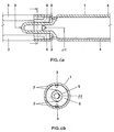
- the dielectric barrier discharge lamp essentially comprises a tubular discharge vessel 1, two strip-shaped internal (main) electrodes (not shown), two strip-shaped external auxiliary electrodes 2 and two supply leads 3. The main electrodes are in electrical contact with the supply leads (not shown). Dielectric barrier 4 covering each electrode is shown in FIG. 1a.
- the general concept of this kind of dielectric barrier discharge lamp with internal (main) electrodes is described in detail in US 6,097,155, particularly in the description of FIGS. 1a, 1b and 2 therein.
- the discharge vessel 1 is sealed in a gas-tight fashion at its first end by means of a flare mount with a tipped-off exhaust tube 5 and at its second end by a dome (not shown) formed from the vessel.
- the discharge vessel 1 is filled with Xenon at a filling pressure of 15 kPa.
- Each auxiliary electrode 2 is U-shaped. A first shank of each U-shaped auxiliary electrode 2 is in electrical contact with one supply lead 3. The second shank of each U-shaped auxiliary electrode 2 is in contact with the outer surface of the exhaust tube 5.
- Each auxiliary electrode 2 is coaxial aligned with the exhaust tube 5 (see FIG 1b). During the ignition phase a high voltage is applied to the supply leads 3.
- the strength of the electrical field generated by the auxiliary electrodes 2 within the exhaust tube 5 is higher than within the discharge vessel, because the of the smaller inner diameter of the exhaust tube 5 in comparison to the inner diameter of the discharge vessel 1. Therefore, ignition of an auxiliary dielectric barrier discharge between the auxiliary electrodes 2 and within the interior of the exhaust tube 5 is facilitated. Eventually, the auxiliary discharge initiates the ignition of the main discharge.
- the space between the auxiliary electrodes 2 is insulated with silicon 6.
- arcing can be avoided by applying a silicon gel along the glass surface between the electrodes (not shown). Both auxiliary electrodes 2, the silicon 6, and the high voltage supply leads 3 are integrated to a single structure which is placed onto the lamp and soldered to the main electrodes of the lamp.
- the inner surface of the flare can also be coated with materials with high secondary electron emission capability such as Al 2 O 3 or MgO.
- FIGS. 2a and 2b show a variation of the above lamp with a coating 7 made of MgO on the inner surface of the exhaust tube 5. Since MgO is a good secondary electron emitter, the coating 7 enhances the electron density.
- FIGS. 3a, 3b, 4a, 4b, 5a, 5b and 6a, 6b show further variations of the dielectric barrier discharge lamp as shown in FIGS. 1a, 1b. Further enhancement of starting is achieved by placing metal structures in the interior of the exhaust tube 5, which enhance the strength of the electrical field inside the exhaust tube 5 (metallic field enhancer). In addition, metallic components in the exhaust tube 5 increase the probability for field emission of electrons due to their low work function in comparison to glass or other non conductive oxides.
- FIGS. 3a, 3b show a dielectric barrier discharge lamp with a U-shaped field enhancer 8.
- FIGS. 4a, 4b show a dielectric barrier discharge lamp with a ring-shaped field enhancer 9.
- the metallic field enhancer consists of a metallic layer covering a part of the cylindrical inner wall of the exhaust tube between the auxiliary electrodes.
- the layer is applied as a patch 11 of silver paste which is also used for printing the electrodes.
- the silver patch 11 is formed in a triangular shape on the cylindrical inner wall of the exhaust tube 5 with two of its three corners facing the two auxiliary electrodes 2 and the third corner facing towards the interior of the discharge vessel 1.
- the length of the patch 11 in the longitudinal direction of the exhaust tube 5 is about 2 mm. In the direction of the circumference of the cross section of the exhaust tube the patch 11 extends approximately from one auxiliary electrode to the other, therefore covering an angle of approximately 180°.
Landscapes
- Physics & Mathematics (AREA)
- Electromagnetism (AREA)
- Engineering & Computer Science (AREA)
- Plasma & Fusion (AREA)
- Discharge Lamps And Accessories Thereof (AREA)
Abstract
Description
- FIG. 1a
- shows a longitudinal section of a dielectric barrier discharge lamp with auxiliary electrodes for improved ignition according to the invention,
- FIG. 1b
- shows a cross section of the dielectric barrier discharge lamp shown in FIG. 1a,
- FIG. 2a
- shows a longitudinal section of a first variation of the dielectric barrier discharge lamp shown in FIG. 1a additionally having a layer of high secondary electron emission capability,
- FIG. 2b
- shows a cross section of the dielectric barrier discharge lamp shown in FIG. 2a,
- FIG. 3a
- shows a longitudinal section of a second variation of the dielectric barrier discharge lamp shown in FIG. 1a additionally having a U-shaped field enhancer,
- FIG. 3b
- shows a cross section of the dielectric barrier discharge lamp shown in FIG. 3a,
- FIG. 4a
- shows a longitudinal section of a third variation of the dielectric barrier discharge lamp shown in FIG. 1a additionally having a ring-shaped field enhancer,
- FIG. 4b
- shows a cross section of the dielectric barrier discharge lamp shown in FIG. 4a,
- FIG. 5a
- shows a longitudinal section of a fourth variation of the dielectric barrier discharge lamp shown in FIG. 1a additionally having a coil-shaped field enhancer,
- FIG. 5b
- shows a cross section of the dielectric barrier discharge lamp shown in FIG. 5a,
- FIG. 6a
- shows a longitudinal section of a fifth variation of the dielectric barrier discharge lamp shown in FIG. 1a additionally having a patch-shaped field enhancer,
- FIG. 6b
- shows a cross section of the dielectric barrier discharge lamp shown in FIG. 6a.
Claims (19)
- Dielectric barrier discharge lamp comprising a discharge vessel (1) having at least one tipped-off exhaust tube (5), the discharge vessel (1) being filled with a filling gas, and main electrodes, characterised by at least one means for igniting an auxiliary discharge inside said exhaust tube (5).
- Dielectric barrier discharge lamp according to claim 1, wherein the means for igniting is at least one auxiliary electrode (2) provided along the exhaust tube (5).
- Dielectric barrier discharge lamp according to claim 2, wherein the at least one auxiliary electrode (2) is belt shaped.
- Dielectric barrier discharge lamp according to claim 2 or 3, wherein the at least one auxiliary electrode (2) is coaxial with the exhaust tube (5).
- Dielectric barrier discharge lamp according to claim 1, wherein the means for igniting is a coil wound around the exhaust tube.
- Dielectric barrier discharge lamp according to any preceding claim, wherein the means for igniting (2) is in electrical contact with a main electrode.
- Dielectric barrier discharge lamp according to any preceding claim, wherein at least a part of the inner surface of the exhaust tube (5) is covered with a material (7) having a high secondary electron emission coefficient.
- Dielectric barrier discharge lamp according to claim 7, wherein the material (7) with high electron emission coefficient is MgO or Al2O3 or a mixture thereof.
- Dielectric barrier discharge lamp according to any preceding claim, which also comprises a metallic structure (8; 9; 10) arranged inside the exhaust tube (5).
- Dielectric barrier discharge lamp according to claim 9, wherein the metallic structure (8) is U-shaped.
- Dielectric barrier discharge lamp according to claim 9, wherein the metallic structure (9) is ring-shaped.
- Dielectric barrier discharge lamp according to claim 9, wherein the metallic structure (10) is coil-shaped.
- Dielectric barrier discharge lamp according to claim 9, wherein the metallic structure (10) is patch-shaped.
- Dielectric barrier discharge lamp according to any of the claims 9 to 13, wherein the work function of the material of the metallic structure (8; 9; 10) is low.
- Dielectric barrier discharge lamp according to any of the claims 9 to 13, wherein the metallic structure is covered with a material lowering the work function.
- Dielectric barrier discharge lamp according to any preceding claim, wherein the at least one auxiliary electrode (2) is covered at least in part by an insulating material (6).
- Dielectric barrier discharge lamp according to claim 16, wherein the insulating material (6) is silicon.
- Dielectric barrier discharge lamp according to claim 16 or 17, wherein the insulating material (6) is a gel.
- Dielectric barrier discharge lamp according to any preceding claim, wherein the discharge vessel (1) is tubular, and the main electrodes are belt-shaped being arranged on the outer or inner surface of the discharge vessel.
Priority Applications (2)
| Application Number | Priority Date | Filing Date | Title |
|---|---|---|---|
| EP02023147A EP1329944A3 (en) | 2001-12-14 | 2002-10-15 | Dielectric barrier discharge lamp with starting aid |
| CA 2414454 CA2414454A1 (en) | 2001-12-14 | 2002-12-11 | Dielectric barrier discharge lamp with starting aid |
Applications Claiming Priority (3)
| Application Number | Priority Date | Filing Date | Title |
|---|---|---|---|
| EP01129856A EP1328007A1 (en) | 2001-12-14 | 2001-12-14 | Dielectric barrier discharge lamp with starting aid. |
| EP01129856 | 2001-12-14 | ||
| EP02023147A EP1329944A3 (en) | 2001-12-14 | 2002-10-15 | Dielectric barrier discharge lamp with starting aid |
Publications (2)
| Publication Number | Publication Date |
|---|---|
| EP1329944A2 true EP1329944A2 (en) | 2003-07-23 |
| EP1329944A3 EP1329944A3 (en) | 2009-11-04 |
Family
ID=26076796
Family Applications (1)
| Application Number | Title | Priority Date | Filing Date |
|---|---|---|---|
| EP02023147A Withdrawn EP1329944A3 (en) | 2001-12-14 | 2002-10-15 | Dielectric barrier discharge lamp with starting aid |
Country Status (2)
| Country | Link |
|---|---|
| EP (1) | EP1329944A3 (en) |
| CA (1) | CA2414454A1 (en) |
Cited By (4)
| Publication number | Priority date | Publication date | Assignee | Title |
|---|---|---|---|---|
| EP1643538A3 (en) * | 2004-09-29 | 2008-02-13 | Patent-Treuhand-Gesellschaft für elektrische Glühlampen mbH | Dielectric barrier discharge lamp with electrical screening |
| WO2008113657A1 (en) * | 2007-03-22 | 2008-09-25 | Osram Gesellschaft mit beschränkter Haftung | Dielectric barrier discharge lamp with starting aid |
| US7573201B2 (en) | 2004-09-29 | 2009-08-11 | Osram Gesellschaft Mit Beschraenkter Haftung | Dielectric barrier discharge lamp having pluggable electrodes |
| EP1598852A3 (en) * | 2004-05-12 | 2010-10-20 | Patent-Treuhand-Gesellschaft für elektrische Glühlampen mbH | Tubular, dielectrical barrier discharge lamp and method of its manufacture |
Family Cites Families (4)
| Publication number | Priority date | Publication date | Assignee | Title |
|---|---|---|---|---|
| DE19718395C1 (en) * | 1997-04-30 | 1998-10-29 | Patent Treuhand Ges Fuer Elektrische Gluehlampen Mbh | Fluorescent lamp and method of operating it |
| JP2002540583A (en) * | 1999-03-25 | 2002-11-26 | コーニンクレッカ フィリップス エレクトロニクス エヌ ヴィ | Lighting equipment |
| EP1111656A4 (en) * | 1999-06-07 | 2007-03-28 | Toshiba Lighting & Technology | DISCHARGE TUBE, DISCHARGE TUBE DEVICE AND IMAGE READER |
| JP3491566B2 (en) * | 1999-07-05 | 2004-01-26 | ウシオ電機株式会社 | Dielectric barrier discharge lamp |
-
2002
- 2002-10-15 EP EP02023147A patent/EP1329944A3/en not_active Withdrawn
- 2002-12-11 CA CA 2414454 patent/CA2414454A1/en not_active Abandoned
Cited By (5)
| Publication number | Priority date | Publication date | Assignee | Title |
|---|---|---|---|---|
| EP1598852A3 (en) * | 2004-05-12 | 2010-10-20 | Patent-Treuhand-Gesellschaft für elektrische Glühlampen mbH | Tubular, dielectrical barrier discharge lamp and method of its manufacture |
| EP1643538A3 (en) * | 2004-09-29 | 2008-02-13 | Patent-Treuhand-Gesellschaft für elektrische Glühlampen mbH | Dielectric barrier discharge lamp with electrical screening |
| US7573201B2 (en) | 2004-09-29 | 2009-08-11 | Osram Gesellschaft Mit Beschraenkter Haftung | Dielectric barrier discharge lamp having pluggable electrodes |
| WO2008113657A1 (en) * | 2007-03-22 | 2008-09-25 | Osram Gesellschaft mit beschränkter Haftung | Dielectric barrier discharge lamp with starting aid |
| CN101632149B (en) * | 2007-03-22 | 2011-08-31 | 奥斯兰姆有限公司 | Dielectric barrier discharge lamp with starting aid |
Also Published As
| Publication number | Publication date |
|---|---|
| CA2414454A1 (en) | 2003-06-14 |
| EP1329944A3 (en) | 2009-11-04 |
Similar Documents
| Publication | Publication Date | Title |
|---|---|---|
| KR100474158B1 (en) | High-pressure discharge lamp | |
| US6172462B1 (en) | Ceramic metal halide lamp with integral UV-enhancer | |
| US4940923A (en) | Electrodeless low-pressure discharge lamp | |
| US6380679B1 (en) | Short-arc discharge lamp with a starting antenna | |
| US6800997B2 (en) | Cold-cathode fluorescent lamp | |
| US8013508B2 (en) | High-pressure discharge lamp | |
| US6924599B2 (en) | Dielectric barrier discharge lamp with starting aid | |
| US6960874B2 (en) | Tubular discharge lamp with ignition aid | |
| US7187131B2 (en) | Discharge lamp with internal starting electrode | |
| US6777878B2 (en) | Dielectric barrier discharge lamp having an ignition means | |
| WO2001045468A2 (en) | High-pressure discharge lamp | |
| CA2414454A1 (en) | Dielectric barrier discharge lamp with starting aid | |
| US4358701A (en) | Discharge lamps having internal starting aid capacitively coupled to one of the electrodes | |
| US6762558B2 (en) | Low-pressure gas discharge lamp | |
| JP3424459B2 (en) | Electrodeless lamp | |
| JP2004152605A (en) | Discharge lamp and liquid crystal backlight device | |
| GB2089115A (en) | Lead-in mount for discharge lamps | |
| WO1998040900A9 (en) | Starting aid for low pressure discharge lamp | |
| JPH097548A (en) | Cold cathode low pressure discharge lamp | |
| US20040160182A1 (en) | Low-pressure discharge lamp | |
| CA2283824A1 (en) | Starting aid for low pressure discharge lamp |
Legal Events
| Date | Code | Title | Description |
|---|---|---|---|
| PUAI | Public reference made under article 153(3) epc to a published international application that has entered the european phase |
Free format text: ORIGINAL CODE: 0009012 |
|
| AK | Designated contracting states |
Designated state(s): AT BE BG CH CY CZ DE DK EE ES FI FR GB GR IE IT LI LU MC NL PT SE SK TR |
|
| AX | Request for extension of the european patent |
Extension state: AL LT LV MK RO SI |
|
| PUAL | Search report despatched |
Free format text: ORIGINAL CODE: 0009013 |
|
| AK | Designated contracting states |
Kind code of ref document: A3 Designated state(s): AT BE BG CH CY CZ DE DK EE ES FI FR GB GR IE IT LI LU MC NL PT SE SK TR |
|
| AX | Request for extension of the european patent |
Extension state: AL LT LV MK RO SI |
|
| 17P | Request for examination filed |
Effective date: 20100308 |
|
| AKX | Designation fees paid |
Designated state(s): DE FR GB |
|
| GRAP | Despatch of communication of intention to grant a patent |
Free format text: ORIGINAL CODE: EPIDOSNIGR1 |
|
| STAA | Information on the status of an ep patent application or granted ep patent |
Free format text: STATUS: THE APPLICATION IS DEEMED TO BE WITHDRAWN |
|
| 18D | Application deemed to be withdrawn |
Effective date: 20120829 |