EP1329909A2 - X-ray generator - Google Patents
X-ray generator Download PDFInfo
- Publication number
- EP1329909A2 EP1329909A2 EP02258139A EP02258139A EP1329909A2 EP 1329909 A2 EP1329909 A2 EP 1329909A2 EP 02258139 A EP02258139 A EP 02258139A EP 02258139 A EP02258139 A EP 02258139A EP 1329909 A2 EP1329909 A2 EP 1329909A2
- Authority
- EP
- European Patent Office
- Prior art keywords
- tubular body
- tank
- ray generator
- lumen
- ray
- Prior art date
- Legal status (The legal status is an assumption and is not a legal conclusion. Google has not performed a legal analysis and makes no representation as to the accuracy of the status listed.)
- Withdrawn
Links
Images




Classifications
-
- H—ELECTRICITY
- H05—ELECTRIC TECHNIQUES NOT OTHERWISE PROVIDED FOR
- H05G—X-RAY TECHNIQUE
- H05G1/00—X-ray apparatus involving X-ray tubes; Circuits therefor
- H05G1/02—Constructional details
- H05G1/04—Mounting the X-ray tube within a closed housing
-
- H—ELECTRICITY
- H05—ELECTRIC TECHNIQUES NOT OTHERWISE PROVIDED FOR
- H05G—X-RAY TECHNIQUE
- H05G1/00—X-ray apparatus involving X-ray tubes; Circuits therefor
- H05G1/02—Constructional details
- H05G1/025—Means for cooling the X-ray tube or the generator
Definitions
- the present invention relates to an X-ray generator, or more particularly, to an X-ray generator having a tank, which accommodates a high-voltage assembly and an X-ray tube, has an insulating fluid poured thereinto, and is sealed.
- the volume expansion of the insulating fluid can be compensated for without the necessity of labor-intensive maintenance.
- an X-ray generator having a tank, which accommodates a high-voltage assembly and an X-ray tube assembly, has an insulating fluid poured thereinto, and is sealed, the volume expansion of the insulating fluid is derived from heat dissipation caused by the high-voltage assembly and X-ray tube assembly. This causes the internal pressure of the tank to rise.
- the sack expands or contracts depending on a difference between the luminal pressure of the sack member and the internal pressure of the tank, whereby the luminal pressure of the sack and the internal pressure of the tank become substantially equal to each other.
- the lumen of the sack member communicates with the ambient space at the opening. Therefore, the internal pressure of the tank remains substantially equal to the pressure in the ambient space irrespective of the volume expansion of the insulating fluid.
- the conventional X-ray generators use the rubber sack to compensate for the volume expansion of the insulating fluid.
- an object of the present invention is to provide an X-ray generator capable of compensating for the volume expansion of an insulating fluid without labor-intensive maintenance. Moreover, a cable linking electric circuit cards mounted with a tank between them can be routed so that it will not be an obstacle.
- an X-ray generator having a tank, which accommodates a high-voltage assembly and an X-ray tube assembly, has an insulating fluid poured into, and is sealed.
- a tubular body is included to penetrate through the tank. The lumen of the tubular body opens onto the ambient space at both ends of the tubular body. The tubular body expands or contracts depending on a difference between the luminal pressure thereof and the internal pressure of the tank.
- the tubular body expands or contracts depending on the difference between the luminal pressure thereof and the internal pressure of the tank. Since the lumen of the tubular body opens onto the ambient space, the internal pressure of the tank remains substantially equal to the pressure in the ambient space. Consequently, the volume expansion of the insulating fluid can be compensated for. Since the lumen of the tubular body opens onto the ambient space at both ends of the tubular body, dust floating in the ambient space hardly accumulates in the lumen of the tubular body. This obviates labor-intensive maintenance. Furthermore, the tubular body penetrates through the tank.
- the cable linking the electric circuit cards mounted with the tank between them passes through the lumen of the tubular body, it is unnecessary to route the cable outside the tank. In other words, the cable linking the electric circuit cards with the tank between them can be routed so that it will not be an obstacle.
- an X-ray generator having the same components as the foregoing ones is characterized in that the tubular body is made of an oil-proof rubber material.
- the tubular body is made of an oil-proof material.
- an insulating oil is adopted as the insulating fluid, deterioration of the tubular body can be prevented.
- the tubular body is made of a rubber material, the tubular body can readily expand or contract responsively to a pressure.
- an X-ray generator having the same components as the aforesaid ones is characterized in that the oil-proof rubber material is a nitrile rubber.
- a nitrile rubber (NBR) is adopted as the oil-proof rubber material. Consequently, the tubular body can be manufactured at low cost.
- an X-ray generator having the same components as the aforesaid ones is characterized in that the tubular body penetrates through the tank in a direction of X-irradiation.
- the tubular body penetrates through the tank in the direction of X-irradiation.
- the direction of X-irradiation is often a vertical direction close to a horizontal direction. Even if dust floating in the ambient space enters the lumen of the tubular body, the dust drops through the lower opening of the tubular body but does not accumulate.
- an X-ray generator having the same components as the aforesaid ones is characterized in that the lumen of the tubular body serves as a passage for the cable linking the electric circuit cards mounted with the tubular body between them.
- the cable linking the electric circuit cards passes through the lumen of the tubular body. This obviates the routing of the cable outside the tank. Consequently, the cable can be routed so that it will not be an obstacle.
- an X-ray generator having the same components as the aforesaid ones is characterized in that the electric circuit boards are mounted on an X-ray shooting window side of the tank and on an opposite side thereof.
- the lumen of the tubular body serves as a passage for the cable linking the electric circuit cards mounted with the tank between them.
- the cable linking the electric circuit cards mounted with the tank between them passes through the lumen of the tubular body. This obviates the routing of the cable outside the tank. Consequently, the cable linking the electric circuit cards mounted with the tank between them can be routed so that it will not be an obstacle.
- an X-ray generator having the same components as the aforesaid ones is characterized in that the tubular body has a lip at both ends thereof. When the lips are pressed with attachment plates, the tubular body is locked in the tank and the tank is sealed.
- an X-ray generator having the same components as the aforesaid ones is characterized in that the sectional outline of the tubular body is oblong.
- the tubular body can be readily locked in the tank so that the tank will be kept airtight. Moreover, the tubular body readily expands or contracts responsively to a difference in pressure. Moreover, the cable can be readily passed through the lumen of the tubular body.
- the volume expansion of the insulating fluid derived from heat dissipation caused by the high-voltage assembly and X-ray tube assembly can be compensated for with the expansion or contraction of the tubular body. Moreover, since dust hardly accumulates in the lumen of the tubular body, labor-intensive maintenance is unnecessary. Furthermore, since the cable can be passed through the lumen of the tubular body, the cable will not be routed outside the tank. Consequently, the cable will not be an obstacle, and the neat appearance improves.
- Fig. 1 shows the configuration of an X-ray fluoroscopy system 10 including an X-ray generator 100 in accordance with an embodiment of the present invention.
- the X-ray fluoroscopy system 10 consists mainly of an irradiator 1 including the X-ray generator 100, a cradle 2 on which a subject H lies down, a detector 3 that detects X-rays transmitted by the subject H, a movable C-arm 4 having the irradiator 1 and detector 3 mounted on the ends thereof, and a stand 5 bearing the movable arm 4.
- Fig. 2 is a perspective view showing the appearance of the X-ray generator 100 in accordance with the embodiment of the present invention.
- a tank base 11, a tank side 12, and a tank top 13 constitute a tank that accommodates a high-voltage assembly (23 in Fig. 8) and an X-ray tube assembly (24 in Fig. 8) and that has an insulating oil (30 in Fig. 8) poured thereinto.
- the bottom of the tank base 11 is covered with a bottom cover 14 that protects a bottom-side electric circuit card (22 in Fig. 8).
- the lumen (15c in Fig. 8) of an expandable tubular body 15 made of a rubber material has an opening in the top of the tank top 13.
- the tubular body 15 has a lip thereof (15a in Fig. 8) pressed with an attachment plate 16a and is thus fixed to the tank top 13 so that the tank will be kept airtight.
- an X-ray shooting port 17 has an opening in the top of the tank top 13.
- an X-ray shooting window-side electric circuit card 18 is mounted on the top of the tank top 13.
- a cable 20 coupled to a connector 19 of the X-ray shooting window-side electric circuit card 18 is routed to the bottom-side electric circuit card (22 in Fig. 8) through the lumen (15c in Fig. 8) of the tubular body 15.
- Fig. 3 is a perspective view graphically showing the appearance of a major portion of the X-ray generator 100.
- An X-ray shooting window 21 has an opening in the top of the tank top 13.
- Fig. 4 and Fig. 5 are perspective views graphically showing the appearance of the major portion of the X-ray generator 10 with the bottom cover 14 removed.
- Fig. 6 and Fig. 7 are perspective views graphically showing the appearance of the major portion of the X-ray generator 10 with the tank side 12 and tank top 13 removed.
- Fig. 8 is a cutaway sectional view showing the major portion of the X-ray generator 100.
- the tubular body 15 penetrates through the tank which accommodates the high-voltage assembly 23 and X-ray tube assembly 24 and which has the insulating oil 30 poured thereinto.
- the tubular body 15 has an opening in both the top of the tank top 13 and the bottom of the tank base 11 respectively.
- the tubular body 15 has the lip 15a thereof pressed with the attachment plate 16a, and is thus fixed to the tank top 13 so that the tank will be kept airtight. Moreover, the tubular body 15 has the lip 15b thereof pressed with the attachment plate 16b, and is thus fixed to the tank base 111 so that the tank will be kept airtight.
- the tank side 12 and tank top 13 are molded into a united body.
- Fig. 9(a) is an enlarged sectional view showing the lib 15a of the tubular body 15.
- the lip 15a has a dent 15A formed in order to facilitate deformation of the lip 15a.
- the lip 15b also has a dent, though the dent is not shown.
- Fig. 9(b) is a sectional view showing the section of the tubular body 15 seen from below.
- the sectional outline of the tubular body 15 is oblong.
- Fig. 10 is a table listing the properties of a material made into the tubular body 15.
- the material of the tubular body 15 is butadiene and acrylic nitride (NBR) grade rubber of up to Shore hardness 75.
- the operational temperature ranges from -30°C to 120°C. However, the normal use temperature ranges from 20°C to 70°C.
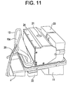
- the tubular body 15, high-voltage assembly 23, X-ray tube assembly 24, and bottom-side electric circuit card 22 are mounted on the tank base 11.
- the cable 20 extending from the bottom-side electric circuit card 22 passes through the lumen 15c of the tubular body 15.
- the tank side 12 and tank top 13 are fixed to the tank base 11 so that the tank will be kept airtight.
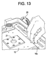
- the lip 15a of the tubular body 15 is exposed on the top of the tank top 13.
- the attachment plate 16a is fixed to the tank top.
- the lip 15a of the tubular body 15 is pressed to the top of the tank top 13 with the attachment plate 16a so that the tank will be kept airtight.
- the insulating oil 30 is poured into the tank.
- the insulating oil 30 is poured at 65°C in a vacuum, and the tank is sealed under an atmospheric pressure. At this time, the tank must be sealed with caution for fear bubbles may be mixed in the insulating oil 30.
- the X-ray shooting window-side electric circuit card 18 and others are mounted on the top of the tank top 13. Moreover, the cable 20 is spliced to the connector of the X-ray shooting window-side electric circuit card 18.
- the foregoing X-ray generator 100 provides the advantages described below.
- the tubular body 15 is made of such a material as a chloroprene rubber (CR), an acrylic rubber (ACM), a fluorocarbon rubber (FKM), a hydrin rubber (ECO, CO), an ethylene-vinyl acetate copolymer rubber, an ethylene-vinyl acetate-acrylate copolymer rubber, an ethylene-acrylate copolymer rubber, or a phosphazene rubber.
- CR chloroprene rubber
- ACM acrylic rubber
- FKM fluorocarbon rubber
- ECO, CO hydrin rubber
- sectional outline of the tubular body 15 may be circular.
Landscapes
- X-Ray Techniques (AREA)
Abstract
Description
Claims (8)
- An X-ray generator having a tank, which accommodates a high-voltage assembly and an X-ray tube assembly, has an insulating fluid poured thereinto, and is sealed, comprising:wherein: the lumen of said tubular body opens onto the ambient space at both ends of said tubular body; anda tubular body penetrating through said tank,
said tubular body expands or contracts depending on a difference between the luminal pressure thereof and the internal pressure of the tank. - The X-ray generator according to Claim 1, wherein said tubular body is made of an oil-proof rubber material.
- The X-ray generator according to Claim 2, wherein said oil-proof rubber material is a nitrile rubber.
- The X-ray generator according to Claim 1, wherein said tubular body penetrates through said tank in a direction of X-irradiation.
- The X-ray generator according to Claim 1, wherein the lumen of said tubular body serves as a passage for a cable.
- The X-ray generator according to Claim 4, wherein: an electric circuit card is mounted on an X-ray shooting window side of said tank and on an opposite side thereof respectively; and the lumen of said tubular body serves as a passage for the cable linking the electric circuit cards mounted with said tank between them.
- The X-ray generator according to Claim 1, wherein: said tubular body has a lip at both ends thereof; and when the lips are pressed with attachment plates, said tubular body is locked in said tank and said tank is sealed.
- The X-ray generator according to Claim 1, wherein the sectional outline of said tubular body is oblong.
Applications Claiming Priority (2)
| Application Number | Priority Date | Filing Date | Title |
|---|---|---|---|
| JP2001360280 | 2001-11-27 | ||
| JP2001360280A JP3892712B2 (en) | 2001-11-27 | 2001-11-27 | X-ray generator |
Publications (2)
| Publication Number | Publication Date |
|---|---|
| EP1329909A2 true EP1329909A2 (en) | 2003-07-23 |
| EP1329909A3 EP1329909A3 (en) | 2009-08-12 |
Family
ID=19171128
Family Applications (1)
| Application Number | Title | Priority Date | Filing Date |
|---|---|---|---|
| EP02258139A Withdrawn EP1329909A3 (en) | 2001-11-27 | 2002-11-27 | X-ray generator |
Country Status (3)
| Country | Link |
|---|---|
| US (1) | US6814488B2 (en) |
| EP (1) | EP1329909A3 (en) |
| JP (1) | JP3892712B2 (en) |
Families Citing this family (12)
| Publication number | Priority date | Publication date | Assignee | Title |
|---|---|---|---|---|
| US7254216B2 (en) * | 2005-07-29 | 2007-08-07 | General Electric Company | Methods and apparatus for filtering a radiation beam and CT imaging systems using same |
| JP4163224B2 (en) * | 2006-07-03 | 2008-10-08 | ジーイー・メディカル・システムズ・グローバル・テクノロジー・カンパニー・エルエルシー | Volume change absorber, X-ray generator, and X-ray imaging apparatus |
| DE102007026677B4 (en) * | 2007-06-08 | 2013-08-22 | Ziehm Imaging Gmbh | X-ray source for a mobile X-ray diagnostic device with a C-arm |
| JP2010067544A (en) * | 2008-09-12 | 2010-03-25 | Ishida Co Ltd | X-ray generator, and x-ray inspection device |
| JP5363775B2 (en) * | 2008-09-12 | 2013-12-11 | 株式会社イシダ | X-ray generator and X-ray inspection apparatus |
| ES2659090T3 (en) | 2009-03-20 | 2018-03-13 | Orthoscan Incorporated | Mobile image capture device |
| JP5477958B2 (en) * | 2010-07-02 | 2014-04-23 | 朝日レントゲン工業株式会社 | X-ray tube container |
| WO2012082799A1 (en) | 2010-12-13 | 2012-06-21 | Orthoscan, Inc. | Mobile fluoroscopic imaging system |
| JP5873688B2 (en) * | 2011-11-04 | 2016-03-01 | 株式会社日立メディコ | High voltage generator for X-ray source |
| CN106328344B (en) | 2014-06-23 | 2018-08-31 | 上海联影医疗科技有限公司 | Ct apparatus |
| JP6543377B1 (en) * | 2018-04-12 | 2019-07-10 | 浜松ホトニクス株式会社 | X-ray generator |
| US12064274B2 (en) | 2021-01-25 | 2024-08-20 | Ariel Eli Bialik | Radiolucent mat and image receptor assembly including same |
Family Cites Families (12)
| Publication number | Priority date | Publication date | Assignee | Title |
|---|---|---|---|---|
| US1941270A (en) | 1928-05-11 | 1933-12-26 | Oscar H Pieper | X-ray apparatus |
| US2036096A (en) | 1928-06-18 | 1936-03-31 | Oscar H Pieper | X-ray apparatus |
| US2153795A (en) * | 1937-11-03 | 1939-04-11 | Robert A Fischer | X-ray apparatus |
| US2194369A (en) | 1939-03-01 | 1940-03-19 | Westinghouse X Ray Co Inc | Shockproof x-ray unit |
| DE744212C (en) * | 1939-08-26 | 1944-01-12 | Electricitaetsgesellschaft San | X-ray device with oil-filled pipe protection housing |
| NL57780C (en) | 1939-10-06 | 1946-07-15 | Philips Nv | Roentgen device, in which the roentgen tube with at least some of the power supplies is housed in a metal housing filled with an insulating liquid |
| US2592496A (en) | 1950-07-20 | 1952-04-08 | Vigh John | X-ray tube head |
| DE8132991U1 (en) | 1981-11-11 | 1983-04-28 | Siemens AG, 1000 Berlin und 8000 München | SINGLE BOILER X-RAY DIAGNOSTIC GENERATOR |
| EP0426898B1 (en) | 1989-11-09 | 1993-08-25 | Siemens Aktiengesellschaft | X-ray emitter |
| DE58905921D1 (en) | 1989-11-09 | 1993-11-18 | Siemens Ag | X-ray tube. |
| DE69116907T2 (en) * | 1990-03-12 | 1996-10-17 | Fuji Photo Film Co Ltd | Color photographic silver halide material |
| DE4220305A1 (en) * | 1991-07-04 | 1993-01-07 | Siemens Ag | HIGH VOLTAGE UNIT |
-
2001
- 2001-11-27 JP JP2001360280A patent/JP3892712B2/en not_active Expired - Fee Related
-
2002
- 2002-11-26 US US10/304,237 patent/US6814488B2/en not_active Expired - Fee Related
- 2002-11-27 EP EP02258139A patent/EP1329909A3/en not_active Withdrawn
Also Published As
| Publication number | Publication date |
|---|---|
| US6814488B2 (en) | 2004-11-09 |
| US20030099326A1 (en) | 2003-05-29 |
| JP2003168592A (en) | 2003-06-13 |
| EP1329909A3 (en) | 2009-08-12 |
| JP3892712B2 (en) | 2007-03-14 |
Similar Documents
| Publication | Publication Date | Title |
|---|---|---|
| US6814488B2 (en) | Oil expansion compensation method for integrated X-ray generator | |
| JP5526096B2 (en) | Electronic controller seal structure | |
| US10244645B2 (en) | Electronic control unit with a housing stabilizing element and housing for electronic control unit | |
| US7161804B2 (en) | Housing structure of electronic device and heat radiation method therefor | |
| US20140211921A1 (en) | Battery pack with integral seal member and electronic device including the same | |
| US7362570B2 (en) | Water-proof housing for electronic equipment | |
| EP1321800A3 (en) | Two-shot molded seal integrity indicator, underwater camera, and method | |
| EP3354952A1 (en) | Clamp for pipe | |
| JP4479643B2 (en) | Camera module and electronic equipment | |
| JPH11330729A (en) | Casing for receiving electrical and / or electronic components | |
| KR20160067997A (en) | Radiography apparatus | |
| CN120334890A (en) | A submarine imaging sonar | |
| CN114186327A (en) | Underwater data cabin shell structure, data cabin and seabed IDC system | |
| US9901004B2 (en) | Housing for electronic control unit | |
| JP2012028781A (en) | Watertight housing having opening covered with plate | |
| CN110494942A (en) | waterproof switch | |
| GB2241833A (en) | A mounting for electronic circuit boards | |
| US20120024876A1 (en) | Sealed enclosure and system | |
| DK0857833T3 (en) | Vacuum insulation board | |
| CN215892922U (en) | Fixing device for refrigerant pipe of refrigeration equipment and refrigeration equipment | |
| JP7378961B2 (en) | radiography equipment | |
| EP3030063A1 (en) | Housing for electronic control unit | |
| US7545437B2 (en) | Digital camera for an optical apparatus including a cooling mechanism for a solid-state imaging device | |
| JPH04275824A (en) | Wire cut discharge machining device | |
| JP6716646B2 (en) | Radiography device |
Legal Events
| Date | Code | Title | Description |
|---|---|---|---|
| PUAI | Public reference made under article 153(3) epc to a published international application that has entered the european phase |
Free format text: ORIGINAL CODE: 0009012 |
|
| AK | Designated contracting states |
Designated state(s): AT BE BG CH CY CZ DE DK EE ES FI FR GB GR IE IT LI LU MC NL PT SE SK TR |
|
| AX | Request for extension of the european patent |
Extension state: AL LT LV MK RO SI |
|
| PUAL | Search report despatched |
Free format text: ORIGINAL CODE: 0009013 |
|
| AK | Designated contracting states |
Kind code of ref document: A3 Designated state(s): AT BE BG CH CY CZ DE DK EE ES FI FR GB GR IE IT LI LU MC NL PT SE SK TR |
|
| AX | Request for extension of the european patent |
Extension state: AL LT LV MK RO SI |
|
| RIC1 | Information provided on ipc code assigned before grant |
Ipc: H05G 1/06 20060101ALI20090706BHEP Ipc: G21K 5/00 20060101AFI20030602BHEP |
|
| 17P | Request for examination filed |
Effective date: 20100212 |
|
| 17Q | First examination report despatched |
Effective date: 20100308 |
|
| AKX | Designation fees paid |
Designated state(s): DE FR |
|
| STAA | Information on the status of an ep patent application or granted ep patent |
Free format text: STATUS: THE APPLICATION IS DEEMED TO BE WITHDRAWN |
|
| 18D | Application deemed to be withdrawn |
Effective date: 20100720 |