EP1329883A1 - Optical disk - Google Patents
Optical disk Download PDFInfo
- Publication number
- EP1329883A1 EP1329883A1 EP01970236A EP01970236A EP1329883A1 EP 1329883 A1 EP1329883 A1 EP 1329883A1 EP 01970236 A EP01970236 A EP 01970236A EP 01970236 A EP01970236 A EP 01970236A EP 1329883 A1 EP1329883 A1 EP 1329883A1
- Authority
- EP
- European Patent Office
- Prior art keywords
- area
- tracks
- lead
- track
- data
- Prior art date
- Legal status (The legal status is an assumption and is not a legal conclusion. Google has not performed a legal analysis and makes no representation as to the accuracy of the status listed.)
- Withdrawn
Links
Images


Classifications
-
- G—PHYSICS
- G11—INFORMATION STORAGE
- G11B—INFORMATION STORAGE BASED ON RELATIVE MOVEMENT BETWEEN RECORD CARRIER AND TRANSDUCER
- G11B7/00—Recording or reproducing by optical means, e.g. recording using a thermal beam of optical radiation by modifying optical properties or the physical structure, reproducing using an optical beam at lower power by sensing optical properties; Record carriers therefor
- G11B7/007—Arrangement of the information on the record carrier, e.g. form of tracks, actual track shape, e.g. wobbled, or cross-section, e.g. v-shaped; Sequential information structures, e.g. sectoring or header formats within a track
-
- G—PHYSICS
- G11—INFORMATION STORAGE
- G11B—INFORMATION STORAGE BASED ON RELATIVE MOVEMENT BETWEEN RECORD CARRIER AND TRANSDUCER
- G11B7/00—Recording or reproducing by optical means, e.g. recording using a thermal beam of optical radiation by modifying optical properties or the physical structure, reproducing using an optical beam at lower power by sensing optical properties; Record carriers therefor
- G11B7/007—Arrangement of the information on the record carrier, e.g. form of tracks, actual track shape, e.g. wobbled, or cross-section, e.g. v-shaped; Sequential information structures, e.g. sectoring or header formats within a track
- G11B7/0079—Zoned data area, e.g. having different data structures or formats for the user data within data layer, Zone Constant Linear Velocity [ZCLV], Zone Constant Angular Velocity [ZCAV], carriers with RAM and ROM areas
-
- G—PHYSICS
- G11—INFORMATION STORAGE
- G11B—INFORMATION STORAGE BASED ON RELATIVE MOVEMENT BETWEEN RECORD CARRIER AND TRANSDUCER
- G11B7/00—Recording or reproducing by optical means, e.g. recording using a thermal beam of optical radiation by modifying optical properties or the physical structure, reproducing using an optical beam at lower power by sensing optical properties; Record carriers therefor
- G11B7/007—Arrangement of the information on the record carrier, e.g. form of tracks, actual track shape, e.g. wobbled, or cross-section, e.g. v-shaped; Sequential information structures, e.g. sectoring or header formats within a track
- G11B7/00718—Groove and land recording, i.e. user data recorded both in the grooves and on the lands
-
- G—PHYSICS
- G11—INFORMATION STORAGE
- G11B—INFORMATION STORAGE BASED ON RELATIVE MOVEMENT BETWEEN RECORD CARRIER AND TRANSDUCER
- G11B7/00—Recording or reproducing by optical means, e.g. recording using a thermal beam of optical radiation by modifying optical properties or the physical structure, reproducing using an optical beam at lower power by sensing optical properties; Record carriers therefor
- G11B7/007—Arrangement of the information on the record carrier, e.g. form of tracks, actual track shape, e.g. wobbled, or cross-section, e.g. v-shaped; Sequential information structures, e.g. sectoring or header formats within a track
- G11B7/00736—Auxiliary data, e.g. lead-in, lead-out, Power Calibration Area [PCA], Burst Cutting Area [BCA], control information
-
- G—PHYSICS
- G11—INFORMATION STORAGE
- G11B—INFORMATION STORAGE BASED ON RELATIVE MOVEMENT BETWEEN RECORD CARRIER AND TRANSDUCER
- G11B7/00—Recording or reproducing by optical means, e.g. recording using a thermal beam of optical radiation by modifying optical properties or the physical structure, reproducing using an optical beam at lower power by sensing optical properties; Record carriers therefor
- G11B7/08—Disposition or mounting of heads or light sources relatively to record carriers
- G11B7/09—Disposition or mounting of heads or light sources relatively to record carriers with provision for moving the light beam or focus plane for the purpose of maintaining alignment of the light beam relative to the record carrier during transducing operation, e.g. to compensate for surface irregularities of the latter or for track following
- G11B7/0938—Disposition or mounting of heads or light sources relatively to record carriers with provision for moving the light beam or focus plane for the purpose of maintaining alignment of the light beam relative to the record carrier during transducing operation, e.g. to compensate for surface irregularities of the latter or for track following servo format, e.g. guide tracks, pilot signals
-
- G—PHYSICS
- G11—INFORMATION STORAGE
- G11B—INFORMATION STORAGE BASED ON RELATIVE MOVEMENT BETWEEN RECORD CARRIER AND TRANSDUCER
- G11B7/00—Recording or reproducing by optical means, e.g. recording using a thermal beam of optical radiation by modifying optical properties or the physical structure, reproducing using an optical beam at lower power by sensing optical properties; Record carriers therefor
- G11B7/24—Record carriers characterised by shape, structure or physical properties, or by the selection of the material
- G11B7/2407—Tracks or pits; Shape, structure or physical properties thereof
- G11B7/24073—Tracks
- G11B7/24079—Width or depth
Definitions
- the present invention relates to optical disks for reproducing and recording data using laser light.
- optical disks have been put into practice as storage media for large-volume data files as well as music and video, but their capacities are constantly increased with the goal of ever larger applications.
- the structure of optical disks for larger capacities is specified in the DVD-RAM standard (ecma-272), for example.
- the track pitch of the ROM (read only memory) area in which overwriting is not possible as well as that in the RAM (random access memory) area in which writing is possible is in both cases 0.74 ⁇ m. This is the same as in the DVD-ROM standard (ecma-267).
- the lead-in area data are recorded on all tracks.
- the track pitch of the ROM area is the same track pitch as in the RAM area, the following problems arise in a configuration in which the data are recorded on all tracks.
- the track pitch at which the ROM area are readable is limited, so that the track pitch of the RAM area cannot be made narrower.
- the present invention solves these problems, and it is an object of the present invention to provide an optical disk in which the same track pitch is maintained for the ROM area and the RAM area, and the specifications for the tracking control can be made the same, even when the recording density of the RAM area has been increased and the tracks have been narrowed.
- an optical disk of the present invention has a ROM area in which overwriting is not possible and a RAM area in which writing is possible, wherein the track pitch of the ROM area and the track pitch of the RAM area are substantially the same, and wherein data in the ROM area have been written into every other track.
- the track pitch is substantially the same means that the track pitch of the ROM area is the same as that of the RAM area, or that if there is a difference between the track pitches of the ROM area and the RAM area, that difference is within a tolerance range of a single tracking control specification.
- the effective track pitch of the data in the ROM area becomes double the track pitch of the RAM area, data can be read out accurately, and at the same time, the tracking control specifications can be shared by the ROM area and the RAM area, even when the tracks of the RAM area are narrowed.
- an optical disk has a ROM area in which writing is impossible and a RAM area in which writing is possible.
- the track pitch of the ROM area is substantially the same as the track pitch of the RAM area, and the data of the ROM area are written on every other track. It is also possible to provide jump areas for jumping to the neighboring track at predetermined positions on the tracks of the ROM area. Thus, even with narrower tracks, it is possible to read out data from the ROM area accurately, while at the same time, the specification for the tracking control can be shared for the ROM area and the RAM area. Moreover, by repeating a jump operation at a predetermined position, it is possible to avoid the useless tracing of unrecorded tracks in the ROM area.
- an optical disk has a ROM area in which writing is impossible and a RAM area in which writing is possible, the track pitch of the ROM area is substantially the same as the track pitch of the RAM area, the data of the ROM area are written on every other track, and the tracks of the ROM area are configured as a double spiral.
- the track pitch of the ROM area is substantially the same as the track pitch of the RAM area
- the data of the ROM area are written on every other track
- the tracks of the ROM area are configured as a double spiral.
- an optical disk has a ROM area in which writing is impossible and a RAM area in which writing is possible, the track pitch of the ROM area is substantially the same as the track pitch of the RAM area, the data of the ROM area are written on every other track, and all tracks are configured as a double spiral.
- the track pitch of the ROM area is substantially the same as the track pitch of the RAM area
- the data of the ROM area are written on every other track
- all tracks are configured as a double spiral.
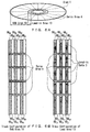
- Fig. 1A and Fig. 1B show a first embodiment of an optical disk of the present invention.
- numeral 1 denotes a disk, whose recording surface is partitioned in the radial direction into a lead-in area 11 and a RAM area 10.
- Numeral 4 denotes servo areas arranged in the radial direction on the disk 1. With these servo areas, the tracking error signal can be detected, as will be explained below in greater detail with Fig. 2 and Fig. 3.
- the tracks on the disk 1 have a spiral-shaped arrangement, in which A tracks 2A and B tracks 2B with different polarity of the tracking error signal are linked together in alternation, with AB track switching positions serving as joints.
- This track configuration and the track pitch are shared by the lead-in area 11 and the RAM area 10.
- the data (lead-in data 3) are recorded only in the A tracks 2A, and no data are recorded in the B tracks 2B, in which there are only the servo areas 4.
- the track pitch of the lead in area 11 is the same as that of the RAM area 10, and when the track pitch of the lead-in area 11 is different from that of the RAM area 10, then that difference should be within a tolerance range of a single specification for the tracking control.
- the track pitches of the lead-in area 11 and the RAM area 10 should be within an error range of about 5% with respect to the specified track pitch.
- this number is merely an example, and the present invention is not limited thereto.
- the track pitches of the lead-in area 11 and of the RAM area 10 can be specified to any numerical range, as long as they are within a tolerance range of a single specification for the tracking control.
- Fig. 2 is a diagram showing the configuration of the servo areas 4.
- Fig. 3 shows a waveform of a reproduction signal in the servo area.
- the servo areas 4 formed along the radial direction on the disk 1 are provided with clock pits 40 for generating a clock and first and second wobble pits 41 and 42 for generating a tracking error signal.
- the clock pits 40 are all placed on the track center, whereas the first and second wobble pits 41 and 42 are placed in alternation on the borders between the A tracks 2A and the B tracks 2B in the radial direction. If the beam irradiated onto the disk 1 moves in the direction indicated by the arrow in Fig.
- the signal detected from the reflecting light is a waveform as shown in Fig. 3.
- the bottom values (w1 and w2) of the first and second wobble pits 41 and 42 are detected, and their difference is taken as the tracking error signal.
- the tracking error signal (TE) has opposite polarities (TE A and TE B ).
- the lead-in data 3 in the lead-in area 11 are output every other rotation, but since there are no data recorded in the tracks (B tracks 2B) neighboring the tracks on which the lead-in data 3 are recorded (A tracks 2A), the track pitch of the lead-in data 3 is doubled, and cross-talk can be reduced significantly. And since the method for producing a tracking error signal and the track pitch are the same for the RAM area 10 and the lead-in area 11, tracking control can be performed with exactly the same configuration.
- the track pitch is shared by all areas on the disk 1 and the tracking error detection can be performed with the servo areas 4 arranged in the radial direction of the disk 1, so that all of the tracking control can be shared for the RAM area 10 and the lead-in area 11.
- the cross-talk during reproduction of the lead-in area 11 can be reduced significantly.
- Fig. 4 shows a second embodiment of an optical disk of the present invention.
- the optical disk 1 in accordance with this embodiment has a jump area 7 in a portion of the lead-in area 12, for jumping during reproduction from the B tracks 2B to the A tracks 2A.
- the jump area 7 is provided directly after the AB track switching position 5. In this jump area 7, no data at all are recorded on the B tracks 2B, and no data that need to be read out are recorded on the A tracks 2A.
- the structural elements besides the jump area 7 are the same as in the first embodiment shown in Fig. 1, so that their further explanation has been omitted.
- the track pitch is shared by all areas on the disk 1 and the tracking error detection can be performed with the servo areas 4 arranged in the radial direction of the disk 1, so that all of the tracking control can be shared for the RAM area 10 and the lead-in area 12.
- the cross-talk during reproduction of the lead-in area 12 can be reduced significantly.
- the track configuration of the RAM area 10 is the same as in the first embodiment shown in Fig. 1, but in the lead-in area 13, there is no AB track switching position 5, and A tracks 6A on which the lead-in data 3 are recorded and B tracks 6B on which no data are recorded are respectively linked to one another continuously in a double spiral configuration.
- the structural elements besides the track configuration of the lead-in area 13 are the same as in the first embodiment shown in Fig. 1, so that their further explanation has been omitted.
- the disk 1 of this embodiment configured as described above When the disk 1 of this embodiment configured as described above is reproduced, if the A tracks 6A on which data are recorded in the lead-in area 13 are tracked, then data can be read in continuously, and data can be read in stably and with high speed without waiting states at unrecorded portions or jump operations to neighboring tracks. Furthermore, as in the first embodiment, the track pitch of the reproduction data is doubled and cross-talk can be reduced significantly. And since the method for producing a tracking error signal and the track pitch are the same for the RAM area 10 and the lead-in area 13, tracking control can be performed with exactly the same configuration.
- the track pitch is shared by all areas on the disk 1 and the tracking error detection can be performed with the servo areas 4 arranged in the radial direction of the disk 1, so that all of the tracking control can be shared for the RAM area 10 and the lead-in area 13.
- the cross-talk during reproduction of the lead-in area 13 can be reduced significantly.
- data can be read in continuously, because the track configuration of the lead-in area 13 is a double spiral configuration of the A tracks and the B tracks.
- the track configuration of the lead-in area 13 is the same as in the third embodiment shown in Fig. 5A and Fig. 5B.
- the RAM area 14 has no AB track switching positions 5, and has a spiral-shaped arrangement, in which A tracks 6A and B tracks 6B with different polarity of the tracking error signal are linked together.
- the structural elements besides the track configuration of the RAM area 14 are the same as in the third embodiment shown in Fig. 5A and Fig. 5B, so that their further explanation has been omitted.
- the disk 1 of this embodiment configured as described above is reproduced, if the A tracks 6A on which data are recorded in the lead-in area 13 are tracked as in the third embodiment, then data can be read in continuously, and data can be read in stably and with high speed without waiting states at unrecorded portions or jump operations to neighboring tracks.
- the tracks 6A and 6B of the RAM area 14 have a double spiral configuration, so that the track configuration at the joint between the lead-in area 13 and the RAM area 14 becomes continuous, and a smooth movement between these areas becomes possible.
- the track pitch of the reproduction data is doubled and cross-talk can be reduced significantly. And since the method for producing a tracking error signal and the track pitch are the same for the RAM area 14 and the lead-in area 13, tracking control can be performed with exactly the same configuration.
- the track pitch is shared by all areas on the disk 1 and the tracking error detection can be performed with the servo areas 4 arranged in the radial direction of the disk 1, so that all of the tracking control can be shared for the RAM area 14 and the lead-in area 13.
- the cross-talk during reproduction of the lead-in area 13 can be reduced significantly.
- data can be read in continuously, because the track configuration of the lead-in area 13 is a double spiral configuration of the A tracks and the B tracks.
- the tracks configuration of the RAM area 14 is a double spiral of the A tracks and the B tracks, so that the track configuration at the joint between these areas becomes continuous, and a smooth movement between these areas becomes possible.
- the servo areas 4 were shared in all areas on the disk 1, but it is also possible to adopt different configurations at the RAM areas 10, 14 and the lead-in areas 11 to 13, and the present invention is not limited to such a configuration. For example, it is possible to perform tracking error detection in the RAM area 10 using grooves, and to perform tracking error detection with pits in the lead-in area 13.
- the lead-in areas 11 to 13 are formed inward from the RAM areas 10 and 14, but it is also possible to form the lead-in areas 11 to 13 at the outermost circumference, or to form them at an intermediate position of the RAM areas 10 and 14, and the present invention is not limited to such a configuration.
- an optical disk can be provided with which the tracking control is shared by the lead-in area and the RAM area by sharing the track pitch, and the cross-talk during reproduction of the lead-in area can be reduced significantly, even when the recording density of the RAM area on the disk is increased.
Landscapes
- Engineering & Computer Science (AREA)
- Software Systems (AREA)
- Theoretical Computer Science (AREA)
- Optical Recording Or Reproduction (AREA)
- Optical Record Carriers And Manufacture Thereof (AREA)
Abstract
Description
Claims (6)
- An optical disk having a ROM area in which overwriting is not possible and a RAM area in which writing is possible,
wherein the track pitch of the ROM area and the track pitch of the RAM area are substantially the same, and
wherein data in the ROM area have been written into every other track. - The optical disk according to claim 1, wherein the tracks on the disk comprise A tracks and B tracks with different polarity of the tracking error signal that are linked together in alternation with a predetermined radial position serving as a joint.
- The optical disk according to claim 1, further comprising, on tracks of the ROM area, a jump area for jumping to a neighboring track in radial direction.
- The optical disk according to claim 3, wherein in the jump area, no data serving a purpose are written into the A tracks or the B tracks.
- The optical disk according to claim 1, wherein the tracks of the ROM area are configured as a double spiral.
- The optical disk according to claim 5, wherein also the tracks of the RAM area are configured as a double spiral.
Applications Claiming Priority (5)
| Application Number | Priority Date | Filing Date | Title |
|---|---|---|---|
| JP2000293733 | 2000-09-27 | ||
| JP2000293733 | 2000-09-27 | ||
| JP2001052917 | 2001-02-27 | ||
| JP2001052917 | 2001-02-27 | ||
| PCT/JP2001/008405 WO2002027717A1 (en) | 2000-09-27 | 2001-09-26 | Optical disk |
Publications (2)
| Publication Number | Publication Date |
|---|---|
| EP1329883A1 true EP1329883A1 (en) | 2003-07-23 |
| EP1329883A4 EP1329883A4 (en) | 2006-04-12 |
Family
ID=26600802
Family Applications (1)
| Application Number | Title | Priority Date | Filing Date |
|---|---|---|---|
| EP01970236A Withdrawn EP1329883A4 (en) | 2000-09-27 | 2001-09-26 | OPTICAL DISK |
Country Status (6)
| Country | Link |
|---|---|
| EP (1) | EP1329883A4 (en) |
| JP (1) | JPWO2002027717A1 (en) |
| KR (1) | KR100544980B1 (en) |
| CN (1) | CN1466753A (en) |
| TW (1) | TW512330B (en) |
| WO (1) | WO2002027717A1 (en) |
Cited By (3)
| Publication number | Priority date | Publication date | Assignee | Title |
|---|---|---|---|---|
| US7903508B2 (en) | 2006-01-26 | 2011-03-08 | Mediatek Inc. | System and method for determining groove/land switching points of an optical disc utilizing a motor rotating signal and original switching points |
| US7961577B2 (en) | 2006-03-10 | 2011-06-14 | Mediatek Inc. | System and method for generating an output signal indicating a specific area on an optical disc utilizing an adjustable specific time |
| US8023370B2 (en) | 2005-10-25 | 2011-09-20 | Mediatek Inc. | Apparatus and method for converting groove/land polarity upon groove/land track change on optical medium |
Family Cites Families (7)
| Publication number | Priority date | Publication date | Assignee | Title |
|---|---|---|---|---|
| US5138598A (en) * | 1990-01-25 | 1992-08-11 | Sony Corporation | Optical disk having relatively wide ram tracks and relatively narrow rom tracks |
| JPH06318371A (en) * | 1993-05-08 | 1994-11-15 | Sony Corp | Disk-shaped recording medium and disk reproducing device |
| JP3065529B2 (en) * | 1996-03-12 | 2000-07-17 | 株式会社リコー | Optical information recording medium and tracking servo method for optical information recording medium |
| TW357345B (en) * | 1996-06-26 | 1999-05-01 | Matsushita Electric Industrial Co Ltd | CD having re-write area and ROM area |
| JP3063641B2 (en) * | 1996-10-02 | 2000-07-12 | 三菱電機株式会社 | optical disk |
| KR100205428B1 (en) * | 1996-12-27 | 1999-07-01 | 구자홍 | Multifocusing laser beam recorder and its multifocusing method |
| JP2000276778A (en) * | 1999-03-25 | 2000-10-06 | Sony Corp | Optical recording medium, master for producing optical recording medium, and optical recording / reproducing apparatus |
-
2001
- 2001-09-26 KR KR1020037004431A patent/KR100544980B1/en not_active Expired - Fee Related
- 2001-09-26 JP JP2002531415A patent/JPWO2002027717A1/en active Pending
- 2001-09-26 WO PCT/JP2001/008405 patent/WO2002027717A1/en not_active Ceased
- 2001-09-26 EP EP01970236A patent/EP1329883A4/en not_active Withdrawn
- 2001-09-26 CN CNA018162991A patent/CN1466753A/en active Pending
- 2001-09-27 TW TW090123869A patent/TW512330B/en not_active IP Right Cessation
Cited By (3)
| Publication number | Priority date | Publication date | Assignee | Title |
|---|---|---|---|---|
| US8023370B2 (en) | 2005-10-25 | 2011-09-20 | Mediatek Inc. | Apparatus and method for converting groove/land polarity upon groove/land track change on optical medium |
| US7903508B2 (en) | 2006-01-26 | 2011-03-08 | Mediatek Inc. | System and method for determining groove/land switching points of an optical disc utilizing a motor rotating signal and original switching points |
| US7961577B2 (en) | 2006-03-10 | 2011-06-14 | Mediatek Inc. | System and method for generating an output signal indicating a specific area on an optical disc utilizing an adjustable specific time |
Also Published As
| Publication number | Publication date |
|---|---|
| KR20030045814A (en) | 2003-06-11 |
| WO2002027717A1 (en) | 2002-04-04 |
| EP1329883A4 (en) | 2006-04-12 |
| JPWO2002027717A1 (en) | 2004-02-05 |
| KR100544980B1 (en) | 2006-01-24 |
| TW512330B (en) | 2002-12-01 |
| CN1466753A (en) | 2004-01-07 |
Similar Documents
| Publication | Publication Date | Title |
|---|---|---|
| JP4215405B2 (en) | optical disk | |
| US20020054548A1 (en) | Optical recording medium, information recording apparatus, and information reproducing apparatus | |
| US20030147338A1 (en) | Optical disk | |
| EP1329883A1 (en) | Optical disk | |
| JP2000011460A (en) | Optical disk | |
| US7068586B2 (en) | Optical disk | |
| EP1772862B1 (en) | Manufacturing method for optical recording medium and optical recording medium | |
| JP3513017B2 (en) | Optical recording medium and optical recording / reproducing apparatus using the same | |
| JP4411262B2 (en) | Optical recording / reproducing device | |
| JP2008516367A (en) | Optical record carrier | |
| JP3947875B2 (en) | Optical disc medium and optical disc recording / reproducing method | |
| JP4411312B2 (en) | Optical disc recording method, optical disc recording / reproducing apparatus, and recorded optical disc | |
| JP2776230B2 (en) | optical disk | |
| US7704580B2 (en) | Information recording medium | |
| JP2001006220A (en) | Optical recording medium | |
| JP3090111B2 (en) | Recording / reproducing apparatus for optical disk recording medium, recording / reproducing method for optical disk recording medium, recording apparatus for optical disk recording medium, and recording method for optical disk recording medium | |
| JP2743907B2 (en) | Track jump method of optical disk | |
| JP2002260239A (en) | Optical disc and optical disc master exposure apparatus | |
| JPH0973635A (en) | Optical information recording medium | |
| JPH03266236A (en) | Information recording medium | |
| US20100322049A1 (en) | Optical disc drive device | |
| JPH09185826A (en) | Disc-shaped information recording medium | |
| JP2002183976A (en) | Optical disc, optical disc recording / reproducing method, and optical disc recording / reproducing apparatus | |
| JP2002183977A (en) | Optical disk, optical disk recording device, and optical disk reproducing device | |
| JPH1196558A (en) | Optical disc, exposure apparatus and method for optical disc master, and method for determining adjacent position of pre-pit portion |
Legal Events
| Date | Code | Title | Description |
|---|---|---|---|
| PUAI | Public reference made under article 153(3) epc to a published international application that has entered the european phase |
Free format text: ORIGINAL CODE: 0009012 |
|
| 17P | Request for examination filed |
Effective date: 20030303 |
|
| AK | Designated contracting states |
Designated state(s): AT BE CH CY DE DK ES FI FR GB GR IE IT LI LU MC NL PT SE TR |
|
| AX | Request for extension of the european patent |
Extension state: AL LT LV MK RO SI |
|
| RBV | Designated contracting states (corrected) |
Designated state(s): DE FR GB |
|
| A4 | Supplementary search report drawn up and despatched |
Effective date: 20060224 |
|
| RIC1 | Information provided on ipc code assigned before grant |
Ipc: G11B 7/09 20060101ALI20060220BHEP Ipc: G11B 7/007 20060101ALI20060220BHEP Ipc: G11B 7/30 20060101AFI20020405BHEP |
|
| RAP1 | Party data changed (applicant data changed or rights of an application transferred) |
Owner name: PANASONIC CORPORATION |
|
| STAA | Information on the status of an ep patent application or granted ep patent |
Free format text: STATUS: THE APPLICATION IS DEEMED TO BE WITHDRAWN |
|
| 18D | Application deemed to be withdrawn |
Effective date: 20060527 |