EP1329863A1 - Aircraft collision avoidance calculation method and system - Google Patents
Aircraft collision avoidance calculation method and system Download PDFInfo
- Publication number
- EP1329863A1 EP1329863A1 EP02001382A EP02001382A EP1329863A1 EP 1329863 A1 EP1329863 A1 EP 1329863A1 EP 02001382 A EP02001382 A EP 02001382A EP 02001382 A EP02001382 A EP 02001382A EP 1329863 A1 EP1329863 A1 EP 1329863A1
- Authority
- EP
- European Patent Office
- Prior art keywords
- trajectory
- avoidance maneuver
- avoidance
- curve
- maneuver
- Prior art date
- Legal status (The legal status is an assumption and is not a legal conclusion. Google has not performed a legal analysis and makes no representation as to the accuracy of the status listed.)
- Withdrawn
Links
- 238000004364 calculation method Methods 0.000 title description 18
- 230000001133 acceleration Effects 0.000 claims abstract description 37
- 238000000034 method Methods 0.000 claims abstract description 20
- 230000014509 gene expression Effects 0.000 claims description 8
- 230000007704 transition Effects 0.000 claims 1
- 239000013598 vector Substances 0.000 description 11
- 230000005484 gravity Effects 0.000 description 5
- 238000004891 communication Methods 0.000 description 2
- RZVHIXYEVGDQDX-UHFFFAOYSA-N 9,10-anthraquinone Chemical compound C1=CC=C2C(=O)C3=CC=CC=C3C(=O)C2=C1 RZVHIXYEVGDQDX-UHFFFAOYSA-N 0.000 description 1
- 230000007423 decrease Effects 0.000 description 1
- 230000000694 effects Effects 0.000 description 1
- 238000012797 qualification Methods 0.000 description 1
- 230000036962 time dependent Effects 0.000 description 1
Images


Classifications
-
- G—PHYSICS
- G08—SIGNALLING
- G08G—TRAFFIC CONTROL SYSTEMS
- G08G5/00—Traffic control systems for aircraft
- G08G5/80—Anti-collision systems
-
- G—PHYSICS
- G01—MEASURING; TESTING
- G01S—RADIO DIRECTION-FINDING; RADIO NAVIGATION; DETERMINING DISTANCE OR VELOCITY BY USE OF RADIO WAVES; LOCATING OR PRESENCE-DETECTING BY USE OF THE REFLECTION OR RERADIATION OF RADIO WAVES; ANALOGOUS ARRANGEMENTS USING OTHER WAVES
- G01S13/00—Systems using the reflection or reradiation of radio waves, e.g. radar systems; Analogous systems using reflection or reradiation of waves whose nature or wavelength is irrelevant or unspecified
- G01S13/88—Radar or analogous systems specially adapted for specific applications
- G01S13/93—Radar or analogous systems specially adapted for specific applications for anti-collision purposes
-
- G—PHYSICS
- G01—MEASURING; TESTING
- G01S—RADIO DIRECTION-FINDING; RADIO NAVIGATION; DETERMINING DISTANCE OR VELOCITY BY USE OF RADIO WAVES; LOCATING OR PRESENCE-DETECTING BY USE OF THE REFLECTION OR RERADIATION OF RADIO WAVES; ANALOGOUS ARRANGEMENTS USING OTHER WAVES
- G01S13/00—Systems using the reflection or reradiation of radio waves, e.g. radar systems; Analogous systems using reflection or reradiation of waves whose nature or wavelength is irrelevant or unspecified
- G01S13/88—Radar or analogous systems specially adapted for specific applications
- G01S13/93—Radar or analogous systems specially adapted for specific applications for anti-collision purposes
- G01S13/933—Radar or analogous systems specially adapted for specific applications for anti-collision purposes of aircraft or spacecraft
-
- G—PHYSICS
- G05—CONTROLLING; REGULATING
- G05D—SYSTEMS FOR CONTROLLING OR REGULATING NON-ELECTRIC VARIABLES
- G05D1/00—Control of position, course, altitude or attitude of land, water, air or space vehicles, e.g. using automatic pilots
- G05D1/10—Simultaneous control of position or course in three dimensions
- G05D1/101—Simultaneous control of position or course in three dimensions specially adapted for aircraft
- G05D1/106—Change initiated in response to external conditions, e.g. avoidance of elevated terrain or of no-fly zones
Definitions
- the present invention relates to a method of calculating a trajectory for an escape maneuver of an airborne vehicle from a determined starting point.
- the invention further relates to an air collision system and a ground collision system arranged to control whether each avoidance maneuver calculated using the above mentioned method in each moment during its calculated lapse is located at a stipulated minimum distance from calculated avoidance maneuver trajectories for other airborne vehicles and at a stipulated minimum distance from a ground profile, respectively.
- Modern military aircraft are automated to increasingly higher degrees. Pilot workload is thereby reduced and aircraft performance and flight security is increased.
- One field of aircraft automation is computer aided collision avoidance systems capable of calculating automated flight sequences. Examples of such systems are ground collision avoidance systems and air collision avoidance systems.
- An existing ground collision avoidance system is arranged to compare a predicted flight path, or trajectory, to a calculated ground profile.
- a warning is presented to the pilot when the margin between the predicted flight path and ground decreases below a certain limit. If the aircraft is not pulled up during a predetermined warning period time, the system is arranged to override pilot commands and engages an avoidance maneuver. As soon as the situation is considered safe, the control is handed back to the pilot.
- the system must operate at a relatively high frequency, characteristically about 30 Hz.
- a conflicting requirement is that the workload imposed on the aircraft system computer must not be heavier than that the computer adequately can perform its other tasks, such as navigation, radar image processing and communication with other computers.
- An existing air collision avoidance system for vehicles is described in WO 01/46933, wherein a possible avoidance maneuver trajectory for the respective vehicle is calculated and compared with the avoidance maneuver trajectories calculated for the other vehicles for controlling whether the avoidance maneuver trajectory of the vehicle in every moment during its calculated lapse is located at a stipulated minimum distance (d) from the avoidance maneuver trajectories of the other vehicles.
- a warning is presented to a person maneuvering the vehicle and/or the vehicle is made to follow an avoidance maneuver trajectory previously calculated and stored for the vehicle if the comparision shows that the avoidance maneuver trajectory of a vehicle in any moment during its calculated lapse is located at a distance from the avoidance maneuver trajectories of any of the other vehicles that is smaller than the stipulated minimum distance (d).
- both system types require a model of how the aircraft will respond to commands, including a prediction of the flight path, in order to calculate when and how to engage the avoidance maneuver.
- a numeric model is used for predicting the aircraft trajectories. The numeric model used involves characteristically many calculation steps and thus the trajectory calculations are imposing a heavy workload on the aircrafts' system computer.
- One purpose of the invention is to provide a new model for calculating aircraft trajectories for use in collision avoidance systems, especially for use in fighter aeroplanes.
- the new model shall require a shortened execution time in the aircraft's system computer compared to known numerical methods. This is an important feature since the computational speed of an aircraft system computer is usually low and not at all comparable to modern desk top machines, due to the long qualification time needed when a new device is to be introduced in a military aircraft.
- said purpose is achieved by means of a method for calculating a trajectory for an escape maneuver of an airborne vehicle according to claim 1.
- the airborne vehicle is for example a fighter aeroplane.
- the method is based on an analytic model wherein the escape maneuver trajectory is modeled as one or more curves continuous in time and lying in the three-dimensional space. In the case of more than one curve, the curves follow after each other. Each curve is described as an analytic expression valid for a specified time period.
- the curve is following the circumference of a circle sector.
- a free fall trajectory component is added to the circle sector circumference.
- the curve can also follow the circumference of an ellipse sector or another analytically described curve with or without the addition of a free fall trajectory.
- each curve is described as a circle sector circumference with or without the addition of a free fall trajectory component.
- each curve is fitted to a foregoing curve, so that for example there is a continuity in the tangential acceleration.
- each escape maneuver trajectory can be described as one or more such parameter equations each valid for a specific time interval.
- the invention further includes an air collision avoidance system according to claim 6 and a ground avoidance system according to claim 7 for use in an airborne vehicle.
- the systems are arranged to calculate a number of avoidance maneuver trajectories starting from a predicted future position and to determine whether each calculated trajectory in each moment during its calculated lapse is located at a stipulated distance from an obstacle(s).
- the obstacles are calculated escape maneuver trajectories for other vehicles.
- the obstacle is the ground and ground profile data are stored in the airborne vehicle. When only one possible escape maneuver remains, an escape maneuver is performed.
- the analytic expression for the own vehicles escape maneuvers and the analytic expressions for the other vehicles escape maneuvers simplifies computation of an interference point or a point in time where the curves are closer than the safe distance d.
- Fig 1 schematically shows two aeroplanes F 1 and F 2 flying in a direction towards each other.
- the aeroplanes are each equipped with an air collision avoidance system, the function of which is illustrated in fig 2.
- the air collision avoidance system will be described in relation to the aeroplane F 1 but it will be understood that the other aeroplane F 2 is equipped with a similar or identical air collision avoidance system.
- the aeroplane F 1 is arranged to continuously calculate 1 its future position P 1 . This is preferably performed in therefore designated software or hardware means.
- the aeroplane F 1 is further arranged to calculate 2 one or several avoidance maneuver trajectories T 1i starting from the calculated future position P 1 .
- the air collision avoidance system is equipped with software and/or hardware means designated for performing these avoidance maneuver trajectory calculations.
- the calculated future position P 1 is based on an assumption on how far and in what direction the plane travels during a predetermined period of time from the current point in time to a point in time hereinafter denoted t avoid .
- the predetermined time period is characteristically 0.4 to 1.0 seconds.
- a model is used which can be made more or less complex depending on the accuracy desired in the system and the computer power that can be used.
- the model is based on the concept that one or more curves following after each other builds up the trajectory.
- the avoidance maneuver calculating function 2 utilizes this model for the calculation of a number of possible avoidance maneuver trajectories T 1i with differing directions from the calculated future positions P 1 .
- the path of the aeroplane F 1 to its calculated future position P 1 can be calculated as a curve in accordance with the same model and thus the path curve and each avoidance maneuver trajectory curve can be expressed as a parametric equation, in which the x-, y- and z-coordinates are functions of time.
- the aircraft is approximated as a point along the path to P 1 and the curves along the trajectory T 1 .
- the aeroplane F 1 is also arranged to determine 3 whether the calculated avoidance maneuver trajectories T 1i of the aeroplane F 1 in each moment during its calculated lapse is located at a stipulated minimum distance d from the avoidance maneuver trajectories T 2i for the other aeroplane. If it is determined that there exists such safe avoidance maneuver trajectories, the data concerning the safe calculated avoidance maneuver trajectories T 1i are stored 4 in a therefore suited storage unit. Thereafter a new future point in time t avoid and corresponding position P 1 is calculated based upon the present position of the aeroplane and the previously described procedure 1-3 is repeated.
- the stipulated minimum distance d corresponds to a predetermined safety distance d safe , possibly supplemented with an error d error corresponding to an estimated maximum error of the calculated avoidance maneuver trajectory T 1 , T 2 .
- the avoidance maneuver trajectories T 2i of the other aeroplane F 2 are for example provided by direct communication between the aeroplanes F 1 , F 2 .
- the warning function 5 can be arranged to present the warning in the form of an acoustic signal and/or a light signal.
- the warning function 5 is also arranged to present an appropriate avoidance maneuver to the pilot, which avoidance maneuver is based on the last stored safe avoidance maneuver trajectory.
- the initial warning is presented a short time before the moment t avoid when an avoidance maneuver based on the last stored safe avoidance maneuver trajectory has to be initiated in order to be able to avoid a collision with certainty.
- the system continues to search after a safe avoidance maneuver trajectory T 1 in which connection a new future position P 1 for the aeroplane is calculated 1 based on the present position of the aeroplane and the previous process is repeated.
- the warning function is inactivated.
- the new safe avoidance maneuver trajectory/-ies is/are stored in the storage unit and a new cycle of calculation follows.
- the system executes 6 an automatic avoidance maneuver based on the last stored safe avoidance maneuver trajectory T 1 .
- Said executing function is arranged to calculate control parameters based on the stored safe avoidance trajectory T 1 by means of which control parameters the aeroplane can be made to perform an avoidance maneuver corresponding to the stored avoidance maneuver trajectory T 1 starting at the moment t avoid .
- the function 1 in F 1 for calculating P 1 is fed with information about current position, velocity and acceleration.
- the predicted point P 1 is in the described example calculated under the assumption that the tangential acceleration is constant during the predetermined interval and the path to the point P 1 is assumed to be circular shaped with a constant radius determined by the current normal acceleration value inputted to the calculation function 1.
- the prediction time period for fighter aeroplanes is short, characteristically about 0.4 to 1.0 seconds, and thus the assumption that the radius during this time period is constant contributes very little to the total error in the calculated position P 1 at the end of the path.
- the above described data inputted to the P 1 calculating function 1 for calculating the position vector, velocity vector and acceleration vector are measured and/or calculated.
- position and velocity data can be fed from a conventional inertial navigation system of the aeroplane to the P 1 calculating function 1.
- the calculating function 1 is arranged to output data for the calculated predicted point P 1 , i.e. r (t avoid ), the calculated velocity ⁇ (t avoid ), and the calculated acceleration a (t avoid ).
- the avoidance maneuver calculating function 2 is arranged to combine simple geometrical curves in order to constitute an analytic solution.
- Each avoidance maneuver trajectory T 1i is constituted by a single curve or by a sequence of curves, each with its own normal acceleration magnitude and direction.
- the number of curves used is a trade off between algorithm simplicity and computational workload on one hand and model accuracy on the other.
- the first curve of the avoidance maneuver trajectory must be fitted to the initial flying conditions, i.e. the curve of the movement to and at the point P 1 .
- the vectors r (t avoid ), v (t avoid ) and a (t avoid ) for the starting point P 1 at the starting time t avoid are outputted to the function 2 and the function 2 fits the first avoidance maneuver trajectory curve to said vectors.
- the curve of the avoidance maneuver trajectory can also be fitted to derivatives of the acceleration in order to improve model accuracy.
- Fig 4 shows a trajectory T 1 calculated according to a model in accordance with a first embodiment of the avoidance maneuver trajectory calculating function 2.
- Each trajectory T 1i starting in P 1 is modeled as a single curve following after an initial circle segment with a radius ⁇ 0 computed by the calculation function 1.
- the path along the left circle represents the calculated path to the point P 1 and the trajectory T 1 to the right of P 1 represents a potential avoidance maneuver modeled as a single curve as will be discussed below.
- the velocity along the trajectory T 1 is affected by the pull of gravity. With an escape roll angle close to 0° the flight path will bend up and the aircraft slow down. For roll angles close to 180°, the aircraft will accelerate. This effect is best modeled as a free fall trajectory added to the circular trajectory. This is seen in fig 4 in that the trajectory deviates from the dashed line. This way of modelling will result in an almost correct velocity.
- the model also predicts a nose drop for an escape roll angle of 90°, which is consistent with simulated avoidance maneuvers
- the elliptical shape of the dashed curve illustrates that the trajectory is following a circle in a plane different from the plane of the first circle placed in the plane of the drawing sheet.
- the avoidance maneuver trajectory of fig 4 is a sum of two paths: a new circular path and a free fall trajectory.
- the free fall trajectory is simple, an acceleration downwards with magnitude g.
- the roll angle and load factor for the avoidance maneuver is used to calculate the new circular path.
- the roll angle of the avoidance maneuver which specifies the direction of the new centripetal acceleration, is measured from the most vertical vector in the normal plane to the velocity.
- the magnitude of the new centripetal acceleration is calculated using variables and data obtainable from the flight control system. These specific calculations will not be described here; the calculation consists of normal steps known to the person skilled in the art. After the new centripetal acceleration has been determined, the calculation of the circular path is similar to the first part of the flight path.
- the avoidance maneuver trajectory is composed of two curved parts following the initial circular element.
- the trajectory will change to a corresponding curve, altering the load factor only.
- the change of roll angle and the order between the two is arbitrary.
- special attention must be brought to the tangential acceleration.
- the trajectory is a sum of a circle and a free fall trajectory, the centripetal acceleration of the circle will no longer be normal to the velocity. Neither will the tangential acceleration be parallel to the velocity. As is seen in fig 6, it is necessary to consider this when calculating the new tangential acceleration.
- the avoidance maneuver calculating function is preferably arranged to calculate several potential escape maneuvers from the predicted point P 1 .
- six possible escape maneuvers are calculated with the escape roll angels in the interval 60° to 180°.
- a ground collision avoidance system of the aeroplane F 1 is arranged to perform mainly in the same manner as the air collision avoidance system explained with reference to fig 2.
- the ground collision avoidance system is arranged to calculate a predicted flight path for a predetermined time interval to a position P 1 .
- the function 1 for calculating the flight path can either be arranged to find the flight path by numerical calculations or by finding an analytic expression.
- the function for calculating the flight path is arranged to deliver coordinates for where the aeroplane is expected to be at the end of the time interval together with velocity and acceleration data to an avoidance maneuver calculating function 2.
- the function 2 is arranged to calculate a number of avoidance maneuver trajectories starting from said future position P 1 in the manner as described in relation to the air collision avoidance system.
- the obtained avoidance maneuver trajectories are fed to a function for determining whether the trajectories in each moment during their calculated lapse are located at a stipulated d distance from a ground profile.
- the ground profile of a terrain is for example provided from a database containing terrain data of the plane. If it is determined that there exists one or more such safe escape maneuvers, the data concerning the calculated avoidance maneuver trajectories are stored in a storage unit 4. Thereafter a new future position P 1 is calculated by the designated function 1 based on the present position of the plane and the previously discussed procedure is repeated.
- a warning 5 is presented to the pilot when there are no avoidance maneuver trajectories for which the distance d is kept for the whole escape maneuver. If the aircraft is not pulled up during the warning time, the system is arranged to override pilot commands and engages an avoidance maneuver. As soon as the situation is considered safe, the control is handled back to the pilot.
- the initial warning is presented a short time before the moment t avoid when an avoidance maneuver based on the last stored safe avoidance maneuver trajectory has to be initiated in order to be able to avoid a collision with certainty.
- the system continues to search after a safe avoidance maneuver trajectory T 1 in which connection a new future position P 1 for the aeroplane is calculated based on the present position of the aeroplane and the previous process is repeated.
- the warning is inactivated.
- the new safe avoidance maneuver trajectory/-ies is/are stored in the storage unit and a new cycle of calculation follows. If no new safe avoidance maneuver trajectory is found during the warning period, i.e. before the moment t avoid , the system executes an automatic avoidance maneuver based on the last stored safe avoidance maneuver trajectory T 1 .
Landscapes
- Engineering & Computer Science (AREA)
- Physics & Mathematics (AREA)
- Radar, Positioning & Navigation (AREA)
- Remote Sensing (AREA)
- General Physics & Mathematics (AREA)
- Aviation & Aerospace Engineering (AREA)
- Electromagnetism (AREA)
- Computer Networks & Wireless Communication (AREA)
- Automation & Control Theory (AREA)
- Traffic Control Systems (AREA)
Abstract
The present invention relates to a method of calculating a trajectory for an escape
maneuver of an airborne vehicle from a determined starting point. The method
comprises the steps of determining position, velocity and acceleration data for the
starting point and from said data determining the escape maneuver. The method is
characterized in that the escape maneuver trajectory is modeled as one or more
analytic curves in three dimensions following after each other. The invention further
relates to an air collision avoidance system and a ground collision avoidance system
comprising said method for calculating escape maneuvers.
Description
- The present invention relates to a method of calculating a trajectory for an escape maneuver of an airborne vehicle from a determined starting point.
- The invention further relates to an air collision system and a ground collision system arranged to control whether each avoidance maneuver calculated using the above mentioned method in each moment during its calculated lapse is located at a stipulated minimum distance from calculated avoidance maneuver trajectories for other airborne vehicles and at a stipulated minimum distance from a ground profile, respectively.
- Modern military aircraft are automated to increasingly higher degrees. Pilot workload is thereby reduced and aircraft performance and flight security is increased. One field of aircraft automation is computer aided collision avoidance systems capable of calculating automated flight sequences. Examples of such systems are ground collision avoidance systems and air collision avoidance systems.
- An existing ground collision avoidance system is arranged to compare a predicted flight path, or trajectory, to a calculated ground profile. A warning is presented to the pilot when the margin between the predicted flight path and ground decreases below a certain limit. If the aircraft is not pulled up during a predetermined warning period time, the system is arranged to override pilot commands and engages an avoidance maneuver. As soon as the situation is considered safe, the control is handed back to the pilot. For adequate performance, the system must operate at a relatively high frequency, characteristically about 30 Hz. A conflicting requirement is that the workload imposed on the aircraft system computer must not be heavier than that the computer adequately can perform its other tasks, such as navigation, radar image processing and communication with other computers.
- An existing air collision avoidance system for vehicles is described in WO 01/46933, wherein a possible avoidance maneuver trajectory for the respective vehicle is calculated and compared with the avoidance maneuver trajectories calculated for the other vehicles for controlling whether the avoidance maneuver trajectory of the vehicle in every moment during its calculated lapse is located at a stipulated minimum distance (d) from the avoidance maneuver trajectories of the other vehicles. A warning is presented to a person maneuvering the vehicle and/or the vehicle is made to follow an avoidance maneuver trajectory previously calculated and stored for the vehicle if the comparision shows that the avoidance maneuver trajectory of a vehicle in any moment during its calculated lapse is located at a distance from the avoidance maneuver trajectories of any of the other vehicles that is smaller than the stipulated minimum distance (d).
- Thus, both system types require a model of how the aircraft will respond to commands, including a prediction of the flight path, in order to calculate when and how to engage the avoidance maneuver. Today, a numeric model is used for predicting the aircraft trajectories. The numeric model used involves characteristically many calculation steps and thus the trajectory calculations are imposing a heavy workload on the aircrafts' system computer.
- One purpose of the invention is to provide a new model for calculating aircraft trajectories for use in collision avoidance systems, especially for use in fighter aeroplanes. The new model shall require a shortened execution time in the aircraft's system computer compared to known numerical methods. This is an important feature since the computational speed of an aircraft system computer is usually low and not at all comparable to modern desk top machines, due to the long qualification time needed when a new device is to be introduced in a military aircraft.
- According to the invention, said purpose is achieved by means of a method for calculating a trajectory for an escape maneuver of an airborne vehicle according to claim 1. The airborne vehicle is for example a fighter aeroplane.
- The method is based on an analytic model wherein the escape maneuver trajectory is modeled as one or more curves continuous in time and lying in the three-dimensional space. In the case of more than one curve, the curves follow after each other. Each curve is described as an analytic expression valid for a specified time period.
- In one embodiment with a single curve, the curve is following the circumference of a circle sector. In another embodiment a free fall trajectory component is added to the circle sector circumference. The curve can also follow the circumference of an ellipse sector or another analytically described curve with or without the addition of a free fall trajectory.
- In an alternative embodiment with two curves or more, each curve is described as a circle sector circumference with or without the addition of a free fall trajectory component. Preferably each curve is fitted to a foregoing curve, so that for example there is a continuity in the tangential acceleration.
- A simple way to describe analytic curves is to describe them in parametric form. In an example where Cartesian coordinates are used each curve is described as the parameter equation x=f(t), y=g(t), z=h(t) for a predetermined time interval. Thus each escape maneuver trajectory can be described as one or more such parameter equations each valid for a specific time interval.
- The invention further includes an air collision avoidance system according to claim 6 and a ground avoidance system according to claim 7 for use in an airborne vehicle.
- The systems are arranged to calculate a number of avoidance maneuver trajectories starting from a predicted future position and to determine whether each calculated trajectory in each moment during its calculated lapse is located at a stipulated distance from an obstacle(s). In the case of an air collision system the obstacles are calculated escape maneuver trajectories for other vehicles. In the case of a ground collision system the obstacle is the ground and ground profile data are stored in the airborne vehicle. When only one possible escape maneuver remains, an escape maneuver is performed.
- During an aerial battle the true flight path is continuously changed and the predicted future position must be updated several times per second. For each update of the future position a new set of escape maneuver trajectories is computed and compared to the obstacles, as discussed above. With the escape maneuver trajectories described as analytic functions, the calculation capacity required for calculating each trajectory is minimized while maintaining the model accuracy.
- In the air collision avoidance system the analytic expression for the own vehicles escape maneuvers and the analytic expressions for the other vehicles escape maneuvers simplifies computation of an interference point or a point in time where the curves are closer than the safe distance d.
- With reference to the enclosed drawing, the invention will hereinbelow be more closely described by means of embodiment examples.
- Fig 1
- schematically shows two aeroplanes equipped with a air/ground collision system according to the invention and avoidance maneuver trajectories calculated for the respective aeroplane.
- Fig 2
- shows a flow chart illustrating the function of the air/ground collision avoidance system in accordance with one embodiment of the present invention,
- Fig 3
- shows an example of the principles of a model implemented in each aeroplane for predicting the path to a point from which the avoidance maneuver trajectories are calculated,
- Fig 4
- shows the predicted path as in fig 3 and the trajectory for an escape maneuver according to a first embodiment of the invention and
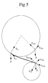
- Fig 5
- shows an escape maneuver trajectory according to a second embodiment of the invention
- Fig 1 schematically shows two aeroplanes F1 and F2 flying in a direction towards each other. The aeroplanes are each equipped with an air collision avoidance system, the function of which is illustrated in fig 2. The air collision avoidance system will be described in relation to the aeroplane F1 but it will be understood that the other aeroplane F2 is equipped with a similar or identical air collision avoidance system. The aeroplane F1 is arranged to continuously calculate 1 its future position P1. This is preferably performed in therefore designated software or hardware means. The aeroplane F1 is further arranged to calculate 2 one or several avoidance maneuver trajectories T1i starting from the calculated future position P1. The air collision avoidance system is equipped with software and/or hardware means designated for performing these avoidance maneuver trajectory calculations.
- The calculated future position P1 is based on an assumption on how far and in what direction the plane travels during a predetermined period of time from the current point in time to a point in time hereinafter denoted tavoid. The predetermined time period is characteristically 0.4 to 1.0 seconds.
- In the calculation of the avoidance maneuver trajectories T1i from the point P1 at the time tavoid, a model is used which can be made more or less complex depending on the accuracy desired in the system and the computer power that can be used. The model is based on the concept that one or more curves following after each other builds up the trajectory. The avoidance maneuver calculating function 2 utilizes this model for the calculation of a number of possible avoidance maneuver trajectories T1i with differing directions from the calculated future positions P1.
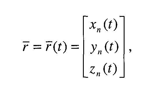
- The path of the aeroplane F1 to its calculated future position P1 can be calculated as a curve in accordance with the same model and thus the path curve and each avoidance maneuver trajectory curve can be expressed as a parametric equation, in which the x-, y- and z-coordinates are functions of time. In this model, the aircraft is approximated as a point along the path to P1 and the curves along the trajectory T1. Its position along the curves will be denotedwherein x1(t), y1(t), z1(t) valid for t0<t<tavoid describes the curve to the point P1, x2(t), y2(t), z2(t) valid for tavoid<t<t2 describes a fist curve of the trajectory T1, x3(t), y3(t), z3(t) valid for t2<t<t3 describes a second curve of the trajectory T1, etc.
- The aeroplane F1 is also arranged to determine 3 whether the calculated avoidance maneuver trajectories T1i of the aeroplane F1 in each moment during its calculated lapse is located at a stipulated minimum distance d from the avoidance maneuver trajectories T2i for the other aeroplane. If it is determined that there exists such safe avoidance maneuver trajectories, the data concerning the safe calculated avoidance maneuver trajectories T1i are stored 4 in a therefore suited storage unit. Thereafter a new future point in time tavoid and corresponding position P1 is calculated based upon the present position of the aeroplane and the previously described procedure 1-3 is repeated. If, on the other hand it is determined that there are no avoidance maneuver trajectories T1i of the aeroplane that all the time during its calculated lapse is located at a distance from the avoidance maneuver trajectories T2i of the other aeroplane equal to or bigger than the stipulated minimum distance d, a warning 5 of the existing risk of collision is activated and thus the pilot is warned. The stipulated minimum distance d corresponds to a predetermined safety distance dsafe, possibly supplemented with an error derror corresponding to an estimated maximum error of the calculated avoidance maneuver trajectory T1, T2. The avoidance maneuver trajectories T2i of the other aeroplane F2 are for example provided by direct communication between the aeroplanes F1, F2.
- The warning function 5 can be arranged to present the warning in the form of an acoustic signal and/or a light signal. Preferably, the warning function 5 is also arranged to present an appropriate avoidance maneuver to the pilot, which avoidance maneuver is based on the last stored safe avoidance maneuver trajectory. The initial warning is presented a short time before the moment tavoid when an avoidance maneuver based on the last stored safe avoidance maneuver trajectory has to be initiated in order to be able to avoid a collision with certainty. After the initial warning has been actuated, the system continues to search after a safe avoidance maneuver trajectory T1 in which connection a new future position P1 for the aeroplane is calculated 1 based on the present position of the aeroplane and the previous process is repeated. If it is determined 3 that one or more new safe avoidance maneuver trajectories have been found, for instance due to the fact that any of the aeroplanes since the previous cycle of calculation has performed such maneuver that an immediate risk of collision is no longer existing, the warning function is inactivated. In this case, the new safe avoidance maneuver trajectory/-ies is/are stored in the storage unit and a new cycle of calculation follows.
- If no new safe avoidance maneuver trajectory is found during the warning period, i.e. before the moment tavoid when the aeroplane has reached the position P1 where the safe avoidance maneuver has to be initiated, the system executes 6 an automatic avoidance maneuver based on the last stored safe avoidance maneuver trajectory T1. Said executing function is arranged to calculate control parameters based on the stored safe avoidance trajectory T1 by means of which control parameters the aeroplane can be made to perform an avoidance maneuver corresponding to the stored avoidance maneuver trajectory T1 starting at the moment tavoid.
- When the automatic avoidance maneuver has been performed, the control of the maneuvering system of the aeroplane is returned to the pilot as soon as possible after the situation is safe again.
- Since data is not known in advance regarding the flight conditions, the aeroplane is assumed to follow a relatively simple path ending in P1. This assumption that the path is simple can only impose a small error to the predicted path compared to the actual path since the time period between the current point in time and the point in time tavoid from which the avoidance maneuver trajectories are calculated is relatively short.
- In accordance with the above, the function 1 in F1 for calculating P1 is fed with information about current position, velocity and acceleration. The predicted point P1 is in the described example calculated under the assumption that the tangential acceleration is constant during the predetermined interval and the path to the point P1 is assumed to be circular shaped with a constant radius determined by the current normal acceleration value inputted to the calculation function 1. The prediction time period for fighter aeroplanes is short, characteristically about 0.4 to 1.0 seconds, and thus the assumption that the radius during this time period is constant contributes very little to the total error in the calculated position P1 at the end of the path.
- Fig 3 illustrates the path to the position P1 modeled as a circle in space, where index zero indicate values at the current point in time, here the current time is set to t0=0. The circle radius ρ is calculated by the following equation
- The position vector
r (t), velocity vectorv (t) and acceleration vectora (t) in the time interval can be described as:r (tavoid), wherein tavoid = tinterval length+ t0. The above described data inputted to the P1 calculating function 1 for calculating the position vector, velocity vector and acceleration vector are measured and/or calculated. For example, position and velocity data can be fed from a conventional inertial navigation system of the aeroplane to the P1 calculating function 1. - The calculating function 1 is arranged to output data for the calculated predicted point P1, i.e.
r (tavoid), the calculated velocityν (tavoid), and the calculated accelerationa (tavoid). - The avoidance maneuver calculating function 2 is arranged to combine simple geometrical curves in order to constitute an analytic solution.
- When the avoidance maneuver is initiated at tavoid, the normal acceleration will change direction and magnitude, and thus the trajectory is continued along a new curve. Each avoidance maneuver trajectory T1i is constituted by a single curve or by a sequence of curves, each with its own normal acceleration magnitude and direction. The number of curves used is a trade off between algorithm simplicity and computational workload on one hand and model accuracy on the other.
- The first curve of the avoidance maneuver trajectory must be fitted to the initial flying conditions, i.e. the curve of the movement to and at the point P1. As stated above, the vectors
r (tavoid),v (tavoid) anda (tavoid) for the starting point P1 at the starting time tavoid are outputted to the function 2 and the function 2 fits the first avoidance maneuver trajectory curve to said vectors. In an extended version the curve of the avoidance maneuver trajectory can also be fitted to derivatives of the acceleration in order to improve model accuracy. - Fig 4 shows a trajectory T1 calculated according to a model in accordance with a first embodiment of the avoidance maneuver trajectory calculating function 2. Each trajectory T1i starting in P1 is modeled as a single curve following after an initial circle segment with a radius ρ0 computed by the calculation function 1. In fig 4 the path along the left circle represents the calculated path to the point P1 and the trajectory T1 to the right of P1 represents a potential avoidance maneuver modeled as a single curve as will be discussed below. The velocity along the trajectory T1 is affected by the pull of gravity. With an escape roll angle close to 0° the flight path will bend up and the aircraft slow down. For roll angles close to 180°, the aircraft will accelerate. This effect is best modeled as a free fall trajectory added to the circular trajectory. This is seen in fig 4 in that the trajectory deviates from the dashed line. This way of modelling will result in an almost correct velocity. The model also predicts a nose drop for an escape roll angle of 90°, which is consistent with simulated avoidance maneuvers.
- The elliptical shape of the dashed curve illustrates that the trajectory is following a circle in a plane different from the plane of the first circle placed in the plane of the drawing sheet.
- To sum up, the avoidance maneuver trajectory of fig 4 is a sum of two paths: a new circular path and a free fall trajectory. For the calculation of the new circular path the new centripetal acceleration must be found. The free fall trajectory is simple, an acceleration downwards with magnitude g.
- The roll angle and load factor for the avoidance maneuver is used to calculate the new circular path. The roll angle of the avoidance maneuver, which specifies the direction of the new centripetal acceleration, is measured from the most vertical vector in the normal plane to the velocity. The magnitude of the new centripetal acceleration is calculated using variables and data obtainable from the flight control system. These specific calculations will not be described here; the calculation consists of normal steps known to the person skilled in the art. After the new centripetal acceleration has been determined, the calculation of the circular path is similar to the first part of the flight path.
- In the position P1 the centripetal acceleration changes abruptly as the flight path changes from one curve to another. However, this can not be allowed for the tangential acceleration, as the aircraft velocity must change smoothly. When the acceleration of gravity is introduced explicitly, the tangential acceleration must therefore be adjusted as follows. The new, adjusted tangential acceleration plus the projection of the acceleration of gravity on the velocity vector must equal the tangential acceleration at the end of the path to P1.
- In a second embodiment of the model, shown in fig 6, the avoidance maneuver trajectory is composed of two curved parts following the initial circular element. At the time when the load factor is to achieve its new value, the trajectory will change to a corresponding curve, altering the load factor only. The same holds for the change of roll angle and the order between the two is arbitrary. When changing from one curve, composed of a circle and a free fall trajectory, to another similar curve, special attention must be brought to the tangential acceleration. When the trajectory is a sum of a circle and a free fall trajectory, the centripetal acceleration of the circle will no longer be normal to the velocity. Neither will the tangential acceleration be parallel to the velocity. As is seen in fig 6, it is necessary to consider this when calculating the new tangential acceleration. The projection of the sum of the previous centripetal and tangential acceleration,
a n 2 a anda v 2 a on the velocity must equal the new tangential accelerationa v 2 b. However, there is no need to consider the acceleration of gravity in this case, as neither gravity nor velocity has changed with the new circle. The equation for the new tangential acceleration is as follows. - The avoidance maneuver calculating function is preferably arranged to calculate several potential escape maneuvers from the predicted point P1. In one example six possible escape maneuvers are calculated with the escape roll angels in the interval 60° to 180°.
- A ground collision avoidance system of the aeroplane F1 is arranged to perform mainly in the same manner as the air collision avoidance system explained with reference to fig 2. Thus, the ground collision avoidance system is arranged to calculate a predicted flight path for a predetermined time interval to a position P1. The function 1 for calculating the flight path can either be arranged to find the flight path by numerical calculations or by finding an analytic expression. The function for calculating the flight path is arranged to deliver coordinates for where the aeroplane is expected to be at the end of the time interval together with velocity and acceleration data to an avoidance maneuver calculating function 2. The function 2 is arranged to calculate a number of avoidance maneuver trajectories starting from said future position P1 in the manner as described in relation to the air collision avoidance system. The obtained avoidance maneuver trajectories are fed to a function for determining whether the trajectories in each moment during their calculated lapse are located at a stipulated d distance from a ground profile. The ground profile of a terrain is for example provided from a database containing terrain data of the plane. If it is determined that there exists one or more such safe escape maneuvers, the data concerning the calculated avoidance maneuver trajectories are stored in a storage unit 4. Thereafter a new future position P1 is calculated by the designated function 1 based on the present position of the plane and the previously discussed procedure is repeated.
- A warning 5 is presented to the pilot when there are no avoidance maneuver trajectories for which the distance d is kept for the whole escape maneuver. If the aircraft is not pulled up during the warning time, the system is arranged to override pilot commands and engages an avoidance maneuver. As soon as the situation is considered safe, the control is handled back to the pilot. The initial warning is presented a short time before the moment tavoid when an avoidance maneuver based on the last stored safe avoidance maneuver trajectory has to be initiated in order to be able to avoid a collision with certainty. After the initial warning has been actuated, the system continues to search after a safe avoidance maneuver trajectory T1 in which connection a new future position P1 for the aeroplane is calculated based on the present position of the aeroplane and the previous process is repeated. If it is determined that one or more new safe avoidance maneuver trajectory has been found, for instance due to the fact that the aeroplane since the previous cycle of calculation has performed such maneuver that an immediate risk of ground collision is no longer existing, the warning is inactivated. In this case, the new safe avoidance maneuver trajectory/-ies is/are stored in the storage unit and a new cycle of calculation follows. If no new safe avoidance maneuver trajectory is found during the warning period, i.e. before the moment tavoid, the system executes an automatic avoidance maneuver based on the last stored safe avoidance maneuver trajectory T1.
Claims (11)
- Method of calculating a trajectory (T) for an escape maneuver of an airborne vehicle, said method comprising the steps of determining state data of the vehicle at a predetermined starting position for the escape maneuver trajectory and from said state data determining said trajectory, wherein the state data includes position, velocity and acceleration data, characterized in that the escape maneuver trajectory is modeled as one or more continuous curves in three dimensions following after each other and in that each curve is described as an analytic expression.
- Method according to claim 1, characterized in that each curve is fitted to the foregoing curve.
- Method according to claim 2, characterized in that the curves are fitted to each other so that there is a continuity in the tangential acceleration.
- Method according to claim 1, characterized in that each curve is modeled to comprise a circle section component.
- Method according to claim 4, characterized in that at least one of the curves further is modeled to comprise a free fall trajectory component.
- Method according to any of the preceding claims, characterized in that each analytic expression is in the form of a parameter equation.
- Air collision avoidance system for an airborne vehicle, said system comprisingcharacterized in that said avoidance maneuver trajectory determining means (2) are arranged to model each trajectory as one or more continuous curves in three dimensions following after each other, wherein each curve is described as an analytic expression.means (1) for continuously calculating a future position,means (2) for determining at least one avoidance maneuver trajectory from said future position,means (3) for controlling whether the avoidance maneuver trajectory in each moment during its calculated lapse is located at a stipulated minimum distance from avoidance maneuver trajectories for other airborne vehicles,
- Ground collision avoidance system for an airborne vehicle, said system comprisingcharacterized in that said avoidance maneuver trajectory determining means (2) are arranged to model each trajectory as one or more continuous curves in three dimensions following after each other, wherein each curve is described as an analytic expression.means (1) for continuously calculating a future position,means (2) for determining at least one avoidance maneuver trajectory from said future position,means (3) for controlling whether the avoidance maneuver trajectory in each moment during its calculated lapse is located at a stipulated minimum distance from a ground profile,
- System according to claim 7 or 8, characterized in that said avoidance maneuver trajectory determining means (2) are arranged to include a circle section component in each curve.
- System according to claim 9, characterized in that said avoidance maneuver trajectory determining means (2) are arranged to include a free fall trajectory component in at least one of the curves.
- System according to any of the claims 7-10, characterized in that said avoidance maneuver trajectory determining means (2) are arranged to design the curves so that there is a continuity in the tangential acceleration in the transitions between the curves.
Priority Applications (1)
| Application Number | Priority Date | Filing Date | Title |
|---|---|---|---|
| EP02001382A EP1329863A1 (en) | 2002-01-19 | 2002-01-19 | Aircraft collision avoidance calculation method and system |
Applications Claiming Priority (1)
| Application Number | Priority Date | Filing Date | Title |
|---|---|---|---|
| EP02001382A EP1329863A1 (en) | 2002-01-19 | 2002-01-19 | Aircraft collision avoidance calculation method and system |
Publications (1)
| Publication Number | Publication Date |
|---|---|
| EP1329863A1 true EP1329863A1 (en) | 2003-07-23 |
Family
ID=8185310
Family Applications (1)
| Application Number | Title | Priority Date | Filing Date |
|---|---|---|---|
| EP02001382A Withdrawn EP1329863A1 (en) | 2002-01-19 | 2002-01-19 | Aircraft collision avoidance calculation method and system |
Country Status (1)
| Country | Link |
|---|---|
| EP (1) | EP1329863A1 (en) |
Cited By (17)
| Publication number | Priority date | Publication date | Assignee | Title |
|---|---|---|---|---|
| EP1630766A1 (en) * | 2004-08-31 | 2006-03-01 | Saab Ab | A system and a method for automatic air collision avoidance |
| EP1630767A1 (en) * | 2004-08-31 | 2006-03-01 | Saab Ab | A system and a method for automatic air collision avoidance |
| EP1742132A1 (en) * | 2005-06-22 | 2007-01-10 | Saab Ab | A method and a calculating unit for calculation of a recovery flight path |
| RU2325705C1 (en) * | 2006-11-23 | 2008-05-27 | Виталий Валерьевич Бондарев | Method to avoid aircraft collision with obstacle and associated device |
| US20110213513A1 (en) * | 2007-09-20 | 2011-09-01 | Michael Naderhirn | Method for automatic avoidance of collisions between a craft and further objects |
| EP3059721A3 (en) * | 2015-02-23 | 2016-11-02 | Honeywell International Inc. | Automated aircraft ground threat avoidance system |
| CN108089594A (en) * | 2017-12-13 | 2018-05-29 | 王俊梅 | A kind of unmanned plane visual dead angles turn to escape flight method |
| RU2664090C1 (en) * | 2017-08-08 | 2018-08-15 | Публичное акционерное общество "Авиационная холдинговая компания "Сухой" | Method and system of prevention of the manned flying machine collision with the earth surface, multifunctional, maneuvered airplane with the warning system of collision with earth surface |
| CN106020215B (en) * | 2016-05-09 | 2018-08-31 | 北京航空航天大学 | A kind of close air combat based on Single-step Prediction matrix games is made decisions on one's own method |
| CN109828600A (en) * | 2019-01-09 | 2019-05-31 | 北京理工大学 | Time optimal quick three-dimensional obstacle-avoiding route planning method |
| CN109903592A (en) * | 2017-12-11 | 2019-06-18 | 上海航空电器有限公司 | A kind of automatic near-earth anti-collision system topographical scan method of high-precision aircraft based on error theory |
| CN112558637A (en) * | 2020-12-11 | 2021-03-26 | 西安航光卫星测控技术有限公司 | Method for avoiding air moving target by unmanned aerial vehicle in unmanned aerial vehicle cluster |
| CN114610078A (en) * | 2022-05-12 | 2022-06-10 | 四川腾盾科技有限公司 | Unmanned aerial vehicle air route conflict early warning method and system |
| CN114684380A (en) * | 2022-04-25 | 2022-07-01 | 北京理工大学 | Guidance method for recovering aerial collision net of aircraft |
| CN115374642A (en) * | 2022-08-31 | 2022-11-22 | 西北工业大学 | Pursuit and escape game method with elliptical motion constraint |
| CN116777008A (en) * | 2023-08-15 | 2023-09-19 | 北京航天晨信科技有限责任公司 | Unmanned aerial vehicle escape prediction modeling-oriented data sample generation method and system |
| CN120993944A (en) * | 2025-10-23 | 2025-11-21 | 浙江孚临科技有限公司 | A method for obstacle avoidance trajectory optimization based on flight embodied intelligence |
Citations (3)
| Publication number | Priority date | Publication date | Assignee | Title |
|---|---|---|---|---|
| US3396391A (en) * | 1963-12-20 | 1968-08-06 | North American Rockwell | Terrain-following system |
| US6201482B1 (en) * | 1996-03-12 | 2001-03-13 | Vdo Luftfahrtgeraete Werk Gmbh | Method of detecting a collision risk and preventing air collisions |
| WO2001046933A1 (en) * | 1999-12-22 | 2001-06-28 | Saab Ab | System and method for avoidance of collision between vehicles |
-
2002
- 2002-01-19 EP EP02001382A patent/EP1329863A1/en not_active Withdrawn
Patent Citations (3)
| Publication number | Priority date | Publication date | Assignee | Title |
|---|---|---|---|---|
| US3396391A (en) * | 1963-12-20 | 1968-08-06 | North American Rockwell | Terrain-following system |
| US6201482B1 (en) * | 1996-03-12 | 2001-03-13 | Vdo Luftfahrtgeraete Werk Gmbh | Method of detecting a collision risk and preventing air collisions |
| WO2001046933A1 (en) * | 1999-12-22 | 2001-06-28 | Saab Ab | System and method for avoidance of collision between vehicles |
Non-Patent Citations (2)
| Title |
|---|
| KOSECKA J ET AL: "2 1/2 D conflict resolution maneuvers for ATMS", PROCEEDINGS OF THE 37TH IEEE CONFERENCE ON DECISION AND CONTROL (CAT. NO.98CH36171), PROCEEDINGS OF THE 37TH IEEE CONFERENCE ON DECISION AND CONTROL, TAMPA, FL, USA, 16-18 DEC. 1998, 1998, Piscataway, NJ, USA, IEEE, USA, pages 2650 - 2655 vol.3, XP002205943, ISBN: 0-7803-4394-8 * |
| KUCHAR J K ET AL: "A review of conflict detection and resolution modeling methods", IEEE TRANSACTIONS ON INTELLIGENT TRANSPORTATION SYSTEMS, DEC. 2000, IEEE, USA, vol. 1, no. 4, pages 179 - 189, XP002205995, ISSN: 1524-9050 * |
Cited By (29)
| Publication number | Priority date | Publication date | Assignee | Title |
|---|---|---|---|---|
| EP1630767A1 (en) * | 2004-08-31 | 2006-03-01 | Saab Ab | A system and a method for automatic air collision avoidance |
| EP1630766A1 (en) * | 2004-08-31 | 2006-03-01 | Saab Ab | A system and a method for automatic air collision avoidance |
| US7516014B2 (en) | 2004-08-31 | 2009-04-07 | Saab Ab | System and a method for automatic air collision avoidance |
| US7711484B2 (en) | 2004-08-31 | 2010-05-04 | Saab Ab | System and a method for automatic air collision avoidance |
| US8249761B2 (en) | 2005-06-22 | 2012-08-21 | Saab Ab | Method and a calculating unit for calculation of a recovery flight path |
| EP1742132A1 (en) * | 2005-06-22 | 2007-01-10 | Saab Ab | A method and a calculating unit for calculation of a recovery flight path |
| US7571878B2 (en) | 2005-06-22 | 2009-08-11 | Saab Ab | Method and a calculating unit for calculation of a recovery flight path |
| RU2325705C1 (en) * | 2006-11-23 | 2008-05-27 | Виталий Валерьевич Бондарев | Method to avoid aircraft collision with obstacle and associated device |
| US20110213513A1 (en) * | 2007-09-20 | 2011-09-01 | Michael Naderhirn | Method for automatic avoidance of collisions between a craft and further objects |
| US8467953B2 (en) | 2007-09-20 | 2013-06-18 | Michael Naderhirn | Method for automatic avoidance of collisions between a craft and further objects |
| EP2193414B1 (en) * | 2007-09-20 | 2018-03-21 | Airbus Defence and Space GmbH | Method for automatically avoiding collisions of a vehicle with other objects |
| EP3059721A3 (en) * | 2015-02-23 | 2016-11-02 | Honeywell International Inc. | Automated aircraft ground threat avoidance system |
| US9547993B2 (en) | 2015-02-23 | 2017-01-17 | Honeywell International Inc. | Automated aircraft ground threat avoidance system |
| CN106020215B (en) * | 2016-05-09 | 2018-08-31 | 北京航空航天大学 | A kind of close air combat based on Single-step Prediction matrix games is made decisions on one's own method |
| RU2664090C1 (en) * | 2017-08-08 | 2018-08-15 | Публичное акционерное общество "Авиационная холдинговая компания "Сухой" | Method and system of prevention of the manned flying machine collision with the earth surface, multifunctional, maneuvered airplane with the warning system of collision with earth surface |
| CN109903592B (en) * | 2017-12-11 | 2022-08-12 | 上海航空电器有限公司 | High-precision aircraft automatic near-ground collision avoidance system terrain scanning method based on error theory |
| CN109903592A (en) * | 2017-12-11 | 2019-06-18 | 上海航空电器有限公司 | A kind of automatic near-earth anti-collision system topographical scan method of high-precision aircraft based on error theory |
| CN108089594B (en) * | 2017-12-13 | 2020-11-27 | 王俊梅 | Unmanned aerial vehicle sight dead angle steering escape flight method |
| CN108089594A (en) * | 2017-12-13 | 2018-05-29 | 王俊梅 | A kind of unmanned plane visual dead angles turn to escape flight method |
| CN109828600A (en) * | 2019-01-09 | 2019-05-31 | 北京理工大学 | Time optimal quick three-dimensional obstacle-avoiding route planning method |
| CN112558637A (en) * | 2020-12-11 | 2021-03-26 | 西安航光卫星测控技术有限公司 | Method for avoiding air moving target by unmanned aerial vehicle in unmanned aerial vehicle cluster |
| CN112558637B (en) * | 2020-12-11 | 2022-11-25 | 西安航光卫星测控技术有限公司 | Method for avoiding air moving target by unmanned aerial vehicle in unmanned aerial vehicle cluster |
| CN114684380A (en) * | 2022-04-25 | 2022-07-01 | 北京理工大学 | Guidance method for recovering aerial collision net of aircraft |
| CN114610078B (en) * | 2022-05-12 | 2022-08-12 | 四川腾盾科技有限公司 | Unmanned aerial vehicle air route conflict early warning method and system |
| CN114610078A (en) * | 2022-05-12 | 2022-06-10 | 四川腾盾科技有限公司 | Unmanned aerial vehicle air route conflict early warning method and system |
| CN115374642A (en) * | 2022-08-31 | 2022-11-22 | 西北工业大学 | Pursuit and escape game method with elliptical motion constraint |
| CN116777008A (en) * | 2023-08-15 | 2023-09-19 | 北京航天晨信科技有限责任公司 | Unmanned aerial vehicle escape prediction modeling-oriented data sample generation method and system |
| CN116777008B (en) * | 2023-08-15 | 2023-11-10 | 北京航天晨信科技有限责任公司 | Unmanned aerial vehicle escape prediction modeling-oriented data sample generation method and system |
| CN120993944A (en) * | 2025-10-23 | 2025-11-21 | 浙江孚临科技有限公司 | A method for obstacle avoidance trajectory optimization based on flight embodied intelligence |
Similar Documents
| Publication | Publication Date | Title |
|---|---|---|
| KR102300324B1 (en) | System and method for controlling formation flight based on anti-collision algorithm | |
| US9243930B2 (en) | Vehicle-based automatic traffic conflict and collision avoidance | |
| Zengin et al. | Real-time target tracking for autonomous UAVs in adversarial environments: A gradient search algorithm | |
| EP3646128B1 (en) | Human supervision of an automated driving system | |
| EP1936584B1 (en) | A device at an airborne vehicle and a method for collision avoidance | |
| EP2555179B1 (en) | Aircraft traffic separation system | |
| US20170097640A1 (en) | Autonomous vehicle control system | |
| US20190196474A1 (en) | Control method, control apparatus, control device, and movable platform | |
| CN110069071A (en) | Navigation of Pilotless Aircraft method and apparatus, storage medium, electronic equipment | |
| EP3975157B1 (en) | Method to navigate an unmanned aerial vehicle to avoid collisions | |
| CN102541069A (en) | Loss of separation avoidance maneuvering | |
| EP3734760B1 (en) | Blind zone tracking method for directional antenna, device therefor, and mobile tracking system | |
| US11014650B2 (en) | Moving body, moving body control system, moving body control method, interface device, and recording medium having program recorded thereon | |
| EP1630766B1 (en) | A system and a method for automatic air collision avoidance | |
| Hebecker et al. | Model-based local path planning for UAVs | |
| KR102752545B1 (en) | Collision avoidance control system and method | |
| CN120447607A (en) | A method and system for autonomous flight trajectory planning of a quadrotor unmanned aerial vehicle | |
| Barfield | Autonomous collision avoidance: the technical requirements | |
| Hoy et al. | Collision-free navigation of an autonomous unmanned helicopter in unknown urban environments: sliding mode and MPC approaches | |
| Yu et al. | Collision avoidance algorithm for a fixed-wing uav utilizing geometric estimation considering multiple dynamic obstacles | |
| Lin et al. | A fast obstacle collision avoidance algorithm for fixed wing uas | |
| Soloviev et al. | Planning of the mobile robot motion in non-deterministic environments with potential fields method | |
| Kielas-Jensen et al. | Persistent monitoring by multiple unmanned aerial vehicles using bernstein polynomials | |
| CN114715194B (en) | Vehicle obstacle avoidance track planning method, device, equipment and storage medium | |
| DeLima et al. | Toward developing an optimal cooperative search algorithm for multiple unmanned aerial vehicles |
Legal Events
| Date | Code | Title | Description |
|---|---|---|---|
| PUAI | Public reference made under article 153(3) epc to a published international application that has entered the european phase |
Free format text: ORIGINAL CODE: 0009012 |
|
| AK | Designated contracting states |
Designated state(s): AT BE CH CY DE DK ES FI FR GB GR IE IT LI LU MC NL PT SE TR |
|
| AX | Request for extension of the european patent |
Extension state: AL LT LV MK RO SI |
|
| 17P | Request for examination filed |
Effective date: 20040123 |
|
| AKX | Designation fees paid |
Designated state(s): AT BE CH CY DE DK ES FI FR GB GR IE IT LI LU MC NL PT SE TR |
|
| 17Q | First examination report despatched |
Effective date: 20040423 |
|
| STAA | Information on the status of an ep patent application or granted ep patent |
Free format text: STATUS: THE APPLICATION IS DEEMED TO BE WITHDRAWN |
|
| 18D | Application deemed to be withdrawn |
Effective date: 20040904 |