EP1329739A2 - Einrichtung zur Aufnahme eines Objektraumes - Google Patents
Einrichtung zur Aufnahme eines Objektraumes Download PDFInfo
- Publication number
- EP1329739A2 EP1329739A2 EP03000170A EP03000170A EP1329739A2 EP 1329739 A2 EP1329739 A2 EP 1329739A2 EP 03000170 A EP03000170 A EP 03000170A EP 03000170 A EP03000170 A EP 03000170A EP 1329739 A2 EP1329739 A2 EP 1329739A2
- Authority
- EP
- European Patent Office
- Prior art keywords
- receiving
- signal
- laser
- channel
- receiving device
- Prior art date
- Legal status (The legal status is an assumption and is not a legal conclusion. Google has not performed a legal analysis and makes no representation as to the accuracy of the status listed.)
- Granted
Links
Images

Classifications
-
- G—PHYSICS
- G01—MEASURING; TESTING
- G01S—RADIO DIRECTION-FINDING; RADIO NAVIGATION; DETERMINING DISTANCE OR VELOCITY BY USE OF RADIO WAVES; LOCATING OR PRESENCE-DETECTING BY USE OF THE REFLECTION OR RERADIATION OF RADIO WAVES; ANALOGOUS ARRANGEMENTS USING OTHER WAVES
- G01S7/00—Details of systems according to groups G01S13/00, G01S15/00, G01S17/00
- G01S7/48—Details of systems according to groups G01S13/00, G01S15/00, G01S17/00 of systems according to group G01S17/00
- G01S7/483—Details of pulse systems
- G01S7/486—Receivers
- G01S7/487—Extracting wanted echo signals, e.g. pulse detection
-
- G—PHYSICS
- G01—MEASURING; TESTING
- G01S—RADIO DIRECTION-FINDING; RADIO NAVIGATION; DETERMINING DISTANCE OR VELOCITY BY USE OF RADIO WAVES; LOCATING OR PRESENCE-DETECTING BY USE OF THE REFLECTION OR RERADIATION OF RADIO WAVES; ANALOGOUS ARRANGEMENTS USING OTHER WAVES
- G01S17/00—Systems using the reflection or reradiation of electromagnetic waves other than radio waves, e.g. lidar systems
- G01S17/02—Systems using the reflection of electromagnetic waves other than radio waves
- G01S17/06—Systems determining position data of a target
- G01S17/08—Systems determining position data of a target for measuring distance only
- G01S17/10—Systems determining position data of a target for measuring distance only using transmission of interrupted, pulse-modulated waves
-
- G—PHYSICS
- G01—MEASURING; TESTING
- G01S—RADIO DIRECTION-FINDING; RADIO NAVIGATION; DETERMINING DISTANCE OR VELOCITY BY USE OF RADIO WAVES; LOCATING OR PRESENCE-DETECTING BY USE OF THE REFLECTION OR RERADIATION OF RADIO WAVES; ANALOGOUS ARRANGEMENTS USING OTHER WAVES
- G01S7/00—Details of systems according to groups G01S13/00, G01S15/00, G01S17/00
- G01S7/48—Details of systems according to groups G01S13/00, G01S15/00, G01S17/00 of systems according to group G01S17/00
- G01S7/483—Details of pulse systems
- G01S7/486—Receivers
- G01S7/4868—Controlling received signal intensity or exposure of sensor
-
- G—PHYSICS
- G01—MEASURING; TESTING
- G01S—RADIO DIRECTION-FINDING; RADIO NAVIGATION; DETERMINING DISTANCE OR VELOCITY BY USE OF RADIO WAVES; LOCATING OR PRESENCE-DETECTING BY USE OF THE REFLECTION OR RERADIATION OF RADIO WAVES; ANALOGOUS ARRANGEMENTS USING OTHER WAVES
- G01S17/00—Systems using the reflection or reradiation of electromagnetic waves other than radio waves, e.g. lidar systems
- G01S17/02—Systems using the reflection of electromagnetic waves other than radio waves
- G01S17/06—Systems determining position data of a target
- G01S17/42—Simultaneous measurement of distance and other co-ordinates
-
- G—PHYSICS
- G01—MEASURING; TESTING
- G01S—RADIO DIRECTION-FINDING; RADIO NAVIGATION; DETERMINING DISTANCE OR VELOCITY BY USE OF RADIO WAVES; LOCATING OR PRESENCE-DETECTING BY USE OF THE REFLECTION OR RERADIATION OF RADIO WAVES; ANALOGOUS ARRANGEMENTS USING OTHER WAVES
- G01S7/00—Details of systems according to groups G01S13/00, G01S15/00, G01S17/00
- G01S7/48—Details of systems according to groups G01S13/00, G01S15/00, G01S17/00 of systems according to group G01S17/00
- G01S7/481—Constructional features, e.g. arrangements of optical elements
- G01S7/4811—Constructional features, e.g. arrangements of optical elements common to transmitter and receiver
- G01S7/4813—Housing arrangements
-
- G—PHYSICS
- G01—MEASURING; TESTING
- G01S—RADIO DIRECTION-FINDING; RADIO NAVIGATION; DETERMINING DISTANCE OR VELOCITY BY USE OF RADIO WAVES; LOCATING OR PRESENCE-DETECTING BY USE OF THE REFLECTION OR RERADIATION OF RADIO WAVES; ANALOGOUS ARRANGEMENTS USING OTHER WAVES
- G01S7/00—Details of systems according to groups G01S13/00, G01S15/00, G01S17/00
- G01S7/48—Details of systems according to groups G01S13/00, G01S15/00, G01S17/00 of systems according to group G01S17/00
- G01S7/481—Constructional features, e.g. arrangements of optical elements
- G01S7/4817—Constructional features, e.g. arrangements of optical elements relating to scanning
-
- G—PHYSICS
- G01—MEASURING; TESTING
- G01S—RADIO DIRECTION-FINDING; RADIO NAVIGATION; DETERMINING DISTANCE OR VELOCITY BY USE OF RADIO WAVES; LOCATING OR PRESENCE-DETECTING BY USE OF THE REFLECTION OR RERADIATION OF RADIO WAVES; ANALOGOUS ARRANGEMENTS USING OTHER WAVES
- G01S7/00—Details of systems according to groups G01S13/00, G01S15/00, G01S17/00
- G01S7/48—Details of systems according to groups G01S13/00, G01S15/00, G01S17/00 of systems according to group G01S17/00
- G01S7/481—Constructional features, e.g. arrangements of optical elements
- G01S7/4818—Constructional features, e.g. arrangements of optical elements using optical fibres
Definitions
- the invention relates to a device for recording an object space an opto-electronic distance measuring device according to a signal transit time method.
- Typical devices of this type include a transmission device for transmission of optical signals, in particular those of a laser, and a receiving channel for receiving optical signals, in particular laser radiation, from objects located in the target area is reflected, and an evaluation device that distance values from the transit time or the phase position of the emitted optical signal determined.
- damping devices can be made of gray filters, for example or aperture diaphragms that exist in the beam path of the receiving device be introduced. Such devices can also be used to reduce the transmission power be used.
- the measurement can be repeated automatically or manually triggered by the user.
- Continuous or quasi-continuous measurements are typical of systems in which a range finder is as described above Art is combined with a scanning device through which the optical Axes of the transmitting and receiving device in two, preferably orthogonal, directions to get distracted.
- a range finder is as described above Art
- Such devices are used to move from an object space, e.g. a terrain formation, a building or a machine or plant to record a distance image. From several, from different Locations taken distance images of an object or from the corresponding Data files can be a 3-D model of the Object can be calculated, then with appropriate CAD or similar programs can be further processed.
- Continuous or quasi-continuous measurements are also used in measurement and Control technology used e.g. to monitor the position of crane systems and other funding agencies.
- the range finder highly reflective target e.g. a retro reflector, such as those described above Recordings can be used as reference marks.
- the resulting level jumps can be well over 30dB and thus Override the receive channel if necessary.
- the map area becomes the receive pulse strongly distorted and the measured distance value falsified accordingly.
- this problem is solved in that at least one further, colinear Receiving channel with reduced sensitivity and a switching stage provided are which switching level for the measurement the signal of that receiving channel Distance measurement uses that of the received signal in an optimal dynamic range is controlled.
- the evaluation device preferably comprises a multi-channel device Timing device.
- the device preferably comprises three receiving channels, the first of which is used as a receiving device includes an avalanche diode or photo multiplier and a work area from about 10 nW to 10 ⁇ W, the second as a receiving device contains a PIN diode and has a working range of approx. 10 ⁇ W to 10 mW and whose third receiving channel contains a photo diode as receiving device and a working range of approx. 10 mW to 10 W with the upstream distribution optics having.
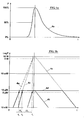
- the pulse diagram of a laser measurement signal is shown in FIG. 1a.
- the laser vibrates first on, reaches a turning point at around 50% of the maximum amplitude and sounds after exceeding the maximum, it decreases comparatively slowly (curve 4a).
- curve 4a The pulse diagram of a laser measurement signal.
- the transmission pulse of the laser is reflected at a target in the object space and by the Receiving device of the range finder added.
- the geometry of the target can be the shape of the receive pulse compared to that of the transmit pulse be changed.
- the amplitude fluctuations are very large count depending on whether the target is far away or in the immediate vicinity of the rangefinder located. Differences also result from the reflectivity of the goal.
- the laser radiation through the targets more or less strongly diffusely reflected, but in the object space is also with reflectors, e.g. retroreflectors to be expected, which reflect the laser radiation in itself and very little dampen. Since modern laser rangefinders have a measuring range of over 1 km, With successive measurements, amplitude differences of up to 90 dB.
- Fig. 1b shows various receive pulses, a logarithmic scale was chosen for better clarification of the amplitude.
- a pulse 4b is received from a distant target with average reflectivity, which has a maximum amplitude of 10 uW.
- the dynamic range of the receiving device is 30 dB (10 nW to 10 ⁇ W), the receiving device is thus maximally modulated. As mentioned above, the 50% point is used for the time measurement (t 1 ). If an echo pulse 4c hits the receiving device from a nearby, highly reflective target, the amplitude is orders of magnitude higher, in the present example by a factor of 10 6 .
- the dynamic range of the receiving device is exceeded, the receiving device reaches a saturation range, so that the pulse is limited to 10 ⁇ W (4d).
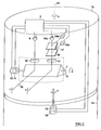
- FIG. 2 is schematic a correspondingly equipped measuring head 1 of a laser scanner is shown.
- the lower part of the measuring head 1a which is attached to a stand, not shown, is the upper part of the measuring head 1 b pivotally mounted about a vertical axis 23.
- The is driven Upper part of the measuring head 1b here by a motor 18.
- Angle decoder 19 reports the respective angular position of the measuring head 1b to an evaluation device 3 back.
- the upper part of the measuring head 1b comprises the laser rangefinder and a mirror prism 8 which is rotatable about a horizontal axis 7. Is driven the mirror prism of a motor 11, on the shaft of which an angle decoder 12 is arranged is.
- the drive of the mirror prism 8 is controlled by the evaluation device 3, which also processes the signals of the angle decoder 12.
- the evaluation device 3 also includes and controls the electronics of the range finder a laser 9 on.
- a laser 9 on This consists of a diode-pumped Q-switched Solid state lasers.
- an optic is designated, which is generally adjusted so that it maps the laser source to infinity.
- the measuring beam 15 deflected in the direction of arrow ⁇ . Is parallel to the transmission channel 9,10 a receiving channel is provided, the optical axis of which is parallel through the mirror prism 8 is deflected to the measuring beam 15.
- the incident radiation is through the optics 13 focused on the photoreceivers 14a to 14c.
- first, partially transmissive mirror 16 In the optical path of the optics 13 is a arranged first, partially transmissive mirror 16, which a large part of the incident radiation directs to a highly sensitive avalanche diode 14a. A small part of the radiation arrives at the second partially transparent mirror 17, which is also the larger one again Deflects part of the radiation, specifically onto the PIN diode 14b. The rest of the radiation hits finally on the photodiode 14c.
- FIG. 3 schematically shows the structure of the control unit 3 in the form of a block diagram of the laser scanner according to the invention, with only the deflection units in this diagram downstream systems are shown.
- the laser transmitter 35 this System works with the passive Q-switched solid-state laser 9, which is operated by diodes 30 is pumped.
- the transmit pulses are also fed to the receivers 14a to 14c.
- This can advantageously be introduced by means of a beam 9 in the solid-state laser 9
- Light guide 53 take place.
- the laser light branched off from the transmission beam path is fed directly to the receivers 14a to 14c via the light guide 53.
- alternative Approaches are based on separate receivers to generate one electrical pulse for the transit time measurement.
- the solid-state laser and the receiving diodes are preferably spectral Characteristic coordinated with each other, the receiving diodes their maximum spectral Have sensitivity in the area in which the laser emits maximally.
- the receiving diodes are next to those emitted by the laser and reflected by the target Radiation much interference radiation in the form of daylight or light of the most varied Receiving artificial light sources, it can be advantageous to the receiving diodes as possible narrow-band optical filter, which has its maximum transmission in has the spectral band in which the laser 9 emits.
- the 3 receiving diodes 14a to 14c are followed by a switching stage 33, which Switches through the signal of that receiving diode to the subsequent receiving channel, which signal drives this receiving channel in an optimal dynamic range.
- the transmit pulse and the echo pulse or the echo pulses digitized and processed.
- This receive channel has a linear dynamic range of 30dB.
- the receiving diodes 14a to 14c and the division mirror 16 and 17 are so coordinated in their sensitivity or in their division ratio that that the total sensitivity of the individual receiving diodes by 30 dB are staggered so that input signals are not overloaded can be processed with a dynamic range of 90 dB.
- the invention is therefore the measurement error described above even in these extreme dynamic ranges avoided and thus achieved maximum accuracy of the system.
- the constant transit time of the reference transmission pulse in the light guide 53 is the time difference between the arrival of the transmission pulse and the Echo pulse determines the distance of the respective object.
- the entire device is clocked by a clock generator 52.
- the processor 34 and data memory 38 are interconnected by a data bus, which is schematic is indicated and designated 39.
- On this data bus 39 are also a Program memory 40 connected to the processor 34, and a data buffer 41, in which raw data after a first evaluation by the processor 34 stored, which are read out at the end of the measuring cycle. From this raw data with algorithms stored in the program memory, a distance value for each individual grid element determined.
- the drive of the mirror prism 8 is controlled by unit 45, that of the measuring head drive by unit 46.
- the data files of the different scan recordings one for each raster element Data set consisting of the two angular coordinates ⁇ and ⁇ , a distance value and possibly other data such as signal amplitude, signal width and shape etc. are stored in a memory 43.
- the further processing of several scan recordings to create a 3-D model of the target area takes place in a computer 42.
- This processing is usually carried out offline.
- the data files obtained from the individual scan recordings are used here ("Point clouds") merged together in the computer 42, with reference marks to be brought to cover.
- the result is a 3-D model that is available as a data file Is available and for example with construction, geodesy, architecture or similar Computer programs can be processed further.
Landscapes
- Engineering & Computer Science (AREA)
- Physics & Mathematics (AREA)
- Computer Networks & Wireless Communication (AREA)
- General Physics & Mathematics (AREA)
- Radar, Positioning & Navigation (AREA)
- Remote Sensing (AREA)
- Electromagnetism (AREA)
- Optical Radar Systems And Details Thereof (AREA)
Abstract
Description
- Fig. 1a
- zeigt das Diagramm eines Laserimpulses, das Diagramm gemäß
- Fig. 1b
- veranschaulicht verschiedene Empfangsimpulse; in
- Fig. 2
- ist der Meßkopf eines Laser-Scanners schematisch dargestellt und in
- Fig. 3
- ist ein Blockschaltbild eines Entfernungsmessers gemäß der Erfindung gezeigt.
Claims (4)
- Einrichtung zur Aufnahme eines Objektraumes mit einer opto-elektronischen Entfernungsmeßeinrichtung nach einem Signal-Laufzeitverfahren mit einer Sendeeinrichtung zum vorzugsweise kontinuierlichen bzw. quasikontinuierlichen Aussenden von optischen Signalen, insbesondere denen eines Lasers, und einem Empfangskanal zum Empfangen von optischen Signalen, insbesondere von Laserstrahlung, die von im Zielraum befindlichen Objekten reflektiert wird, gegebenenfalls mit einer Scan-Einrichtung zur Ablenkung der optischen Achsen von Sende- und Empfangseinrichtung in zwei, vorzugsweise orthogonale Richtungen, ferner mit einer Auswerteeinrichtung, die aus der Laufzeit bzw. der Phasenlage des ausgesandten optischen Signals Entfernungswerte ermittelt,
dadurch gekennzeichnet, daß
mindestens ein weiterer, kolinearer Empfangskanal (14b bzw. 14c) mit reduzierter Empfindlichkeit sowie eine Schaltstufe (33) vorgesehen sind, welche Schaltstufe (33) bei der Messung jeweils das Signal jener Empfangseinrichtung (14a bis 14c) zur Entfernungsmessung heranzieht, die vom Empfangssignal in einem optimalen Dynamikbereich angesteuert wird. - Einrichtung zur Aufnahme eines Objektraumes nach Anspruch 1, dadurch gekennzeichnet, daß die Auswerteeinrichtung eine mehrkanalige Zeitmeßeinrichtung umfaßt.
- Einrichtung nach Anspruch 1 oder 2, dadurch gekennzeichnet, daß den Empfangseinrichtungen (14a bis 14c) der einzelnen Kanäle Teilungsprismen bzw. Teilungsspiegel (16,17) vorgeschaltet sind, deren Teilungsverhältnisse der Empfindlichkeit der jeweiligen Empfangseinrichtung (14a bis 14c), sowie dem maximalen Dynamikbereich der zugehörigen Empfangskanäle (36 und 37) entsprechen, wobei sich beispielsweise bei gleicher Empfindlichkeit der Empfangseinrichtungen und einem maximalen Dynamikbereich der Empfangskanäle von 30 dB ein Teilungsverhältnis des Spiegels oder Prismas von 1000:1 ergibt.
- Einrichtung nach einem der Ansprüche 1 bis 3, dadurch gekennzeichnet, daß die Einrichtung drei Empfangskanäle umfaßt, deren erster als Empfangseinrichtung eine Avalanche-Diode oder einen Photo-Multiplier beinhaltet (14a) und einen Arbeitsbereich von ca. 10 nW bis 10 µW aufweist, deren zweiter als Empfangseinrichtung eine PIN-Diode (14b) beinhaltet und mit der vorgeschalteten Aufteilungsoptik einen Arbeitsbereich von ca. 10 µW bis 10 mW besitzt und deren dritter Empfangskanal als Empfangseinrichtung eine Photo-Diode (14c) beinhaltet und mit der vorgeschalteten Aufteilungsoptik einen Arbeitsbereich von ca. 10 mW bis 10 W aufweist.
Applications Claiming Priority (2)
| Application Number | Priority Date | Filing Date | Title |
|---|---|---|---|
| AT612002 | 2002-01-16 | ||
| AT0006102A AT412029B (de) | 2002-01-16 | 2002-01-16 | Verfahren zur aufnahme eines objektraumes |
Publications (3)
| Publication Number | Publication Date |
|---|---|
| EP1329739A2 true EP1329739A2 (de) | 2003-07-23 |
| EP1329739A3 EP1329739A3 (de) | 2005-01-05 |
| EP1329739B1 EP1329739B1 (de) | 2009-02-25 |
Family
ID=3583057
Family Applications (1)
| Application Number | Title | Priority Date | Filing Date |
|---|---|---|---|
| EP03000170A Expired - Lifetime EP1329739B1 (de) | 2002-01-16 | 2003-01-07 | Einrichtung zur Aufnahme eines Objektraumes |
Country Status (3)
| Country | Link |
|---|---|
| EP (1) | EP1329739B1 (de) |
| AT (1) | AT412029B (de) |
| DE (1) | DE50311204D1 (de) |
Cited By (10)
| Publication number | Priority date | Publication date | Assignee | Title |
|---|---|---|---|---|
| WO2009129552A1 (de) * | 2008-04-22 | 2009-10-29 | Riegl Laser Measurement Systems Gmbh | Vorrichtung und verfahren zum messen des empfangszeitpunkts eines impulses |
| EP2182377A1 (de) * | 2008-10-30 | 2010-05-05 | Sick Ag | Entfernungsmessender Laserscanner |
| EP2306219A3 (de) * | 2009-10-05 | 2011-08-03 | Riegl Laser Measurement Systems GmbH | Laserscanner und Verfharen zum Laserscannen |
| EP2375266A1 (de) * | 2010-04-09 | 2011-10-12 | Sick AG | Optoelektronischer Sensor und Verfahren zur Absicherung |
| EP2375264A1 (de) | 2010-04-08 | 2011-10-12 | Sick AG | Sicherheitsscanner mit Verschmutzungsüberwachung |
| JP2011257193A (ja) * | 2010-06-07 | 2011-12-22 | Ihi Corp | 物体検出装置 |
| AT508504B1 (de) * | 2009-07-14 | 2013-02-15 | Riegl Laser Measurement Sys | Vorrichtung zur entfernungsmessung |
| CN103885065A (zh) * | 2014-03-21 | 2014-06-25 | 中国科学院上海光学精密机械研究所 | 双波长双脉冲的无模糊激光测距装置 |
| CN105445748A (zh) * | 2014-09-18 | 2016-03-30 | 赫克斯冈技术中心 | 光电测距装置和测距方法 |
| EP3091272A1 (de) * | 2015-05-05 | 2016-11-09 | Sick Ag | Lichtgitter |
Family Cites Families (2)
| Publication number | Priority date | Publication date | Assignee | Title |
|---|---|---|---|---|
| DE3103567A1 (de) * | 1981-02-03 | 1982-08-12 | MITEC Moderne Industrietechnik GmbH, 8012 Ottobrunn | Entfernungsmessverfahren nach dem prinzip der laufzeitmessung eines messlichtimpulses und vorrichtung zu seiner durchfuehrung |
| AT409195B (de) * | 2000-04-07 | 2002-06-25 | Riegl Laser Measurement Sys | Einrichtung zur aufnahme eines objektraumes |
-
2002
- 2002-01-16 AT AT0006102A patent/AT412029B/de not_active IP Right Cessation
-
2003
- 2003-01-07 DE DE50311204T patent/DE50311204D1/de not_active Expired - Lifetime
- 2003-01-07 EP EP03000170A patent/EP1329739B1/de not_active Expired - Lifetime
Cited By (15)
| Publication number | Priority date | Publication date | Assignee | Title |
|---|---|---|---|---|
| WO2009129552A1 (de) * | 2008-04-22 | 2009-10-29 | Riegl Laser Measurement Systems Gmbh | Vorrichtung und verfahren zum messen des empfangszeitpunkts eines impulses |
| US8995577B2 (en) | 2008-04-22 | 2015-03-31 | Riegl Laser Measurement Systems Gmbh | Apparatus and method for measurement of the reception time of a pulse |
| EP2182377A1 (de) * | 2008-10-30 | 2010-05-05 | Sick Ag | Entfernungsmessender Laserscanner |
| AT508504B1 (de) * | 2009-07-14 | 2013-02-15 | Riegl Laser Measurement Sys | Vorrichtung zur entfernungsmessung |
| EP2306219A3 (de) * | 2009-10-05 | 2011-08-03 | Riegl Laser Measurement Systems GmbH | Laserscanner und Verfharen zum Laserscannen |
| EP2375264A1 (de) | 2010-04-08 | 2011-10-12 | Sick AG | Sicherheitsscanner mit Verschmutzungsüberwachung |
| EP2375266A1 (de) * | 2010-04-09 | 2011-10-12 | Sick AG | Optoelektronischer Sensor und Verfahren zur Absicherung |
| JP2011257193A (ja) * | 2010-06-07 | 2011-12-22 | Ihi Corp | 物体検出装置 |
| CN103885065A (zh) * | 2014-03-21 | 2014-06-25 | 中国科学院上海光学精密机械研究所 | 双波长双脉冲的无模糊激光测距装置 |
| CN103885065B (zh) * | 2014-03-21 | 2016-04-13 | 中国科学院上海光学精密机械研究所 | 双波长双脉冲的无模糊激光测距装置 |
| CN105445748A (zh) * | 2014-09-18 | 2016-03-30 | 赫克斯冈技术中心 | 光电测距装置和测距方法 |
| EP2998700B1 (de) | 2014-09-18 | 2016-12-07 | Hexagon Technology Center GmbH | Elektrooptischer Distanzmesser und Distanzmessverfahren |
| US10006766B2 (en) | 2014-09-18 | 2018-06-26 | Hexagon Technology Center Gmbh | Electrooptical distance measuring device and distance measuring method |
| EP3091272A1 (de) * | 2015-05-05 | 2016-11-09 | Sick Ag | Lichtgitter |
| US10126416B2 (en) | 2015-05-05 | 2018-11-13 | Sick Ag | Light grid |
Also Published As
| Publication number | Publication date |
|---|---|
| DE50311204D1 (de) | 2009-04-09 |
| EP1329739B1 (de) | 2009-02-25 |
| EP1329739A3 (de) | 2005-01-05 |
| AT412029B (de) | 2004-08-26 |
| ATA612002A (de) | 2004-01-15 |
Similar Documents
| Publication | Publication Date | Title |
|---|---|---|
| AT412032B (de) | Verfahren zur aufnahme eines objektraumes | |
| AT412028B (de) | Einrichtung zur aufnahme eines objektraumes | |
| DE60108029T2 (de) | Vorrichtung zur Positionsbestimmung | |
| DE60028324T2 (de) | Optischer Entfernungsmesser | |
| DE19531632B4 (de) | Entfernungsmeßgerät | |
| EP2293013B1 (de) | 3D-Laservermessungseinrichtung | |
| EP0435011B1 (de) | Entfernungsbildkamera | |
| EP1405037B1 (de) | Vorrichtung zur optischen distanzmessung über einen grossen messbereich | |
| EP0396865B1 (de) | Optisches Radar | |
| AT411299B (de) | Verfahren zur aufnahme eines objektraumes | |
| DE60109113T2 (de) | Vorrichtung zum Erfassen von Abweichungen, Rotierendes Lasergerät, und Positionbestimmungssystem mit Vorrichtung zum Erfassen / Korrigieren von Abweichungen | |
| WO2003016944A2 (de) | Verfahren und vorrichtung zur aufnahme eines dreidimensionalen abstandsbildes | |
| DE10143107A1 (de) | Optoelektronische Entfernungsmeßeinrichtung | |
| AT412029B (de) | Verfahren zur aufnahme eines objektraumes | |
| EP3543648B1 (de) | Opto-elektronisches vermessungsgerät mit scanfunktionalität | |
| AT408818B (de) | Verfahren zur aufnahme eines objektraumes | |
| EP2140286B1 (de) | Vorrichtung und verfahren zum messen des empfangszeitpunkts eines impulses | |
| EP2315053A2 (de) | Vorrichtungen und Verfahren zum Messen der Empfangszeitpunkte von Impulsen | |
| DE10153742A1 (de) | Verfahren und Vorrichtung zur Aufnahme eines dreidimensionalen Abstandsbildes | |
| WO2005064359A1 (de) | Vorrichtung zum messen der distanz zu fernen und nahen objekten | |
| DE10223478B4 (de) | Verfahren zur Aufnahme eines Objektraumes | |
| EP4184202B1 (de) | Optoelektronischer sensor | |
| DE102011121115A1 (de) | Laser-Scanner und Verfahren zur Vermessung von Zielräumen | |
| DE3219452A1 (de) | Dynamik-steuerungsanordnung fuer ein entfernungsmessgeraet | |
| WO1999013356A2 (de) | Opto-elektronisches messverfahren und opto-elektronische messeinrightung |
Legal Events
| Date | Code | Title | Description |
|---|---|---|---|
| PUAI | Public reference made under article 153(3) epc to a published international application that has entered the european phase |
Free format text: ORIGINAL CODE: 0009012 |
|
| AK | Designated contracting states |
Designated state(s): AT BE BG CH CY CZ DE DK EE ES FI FR GB GR HU IE IT LI LU MC NL PT SE SI SK TR |
|
| AX | Request for extension of the european patent |
Extension state: AL LT LV MK RO |
|
| PUAL | Search report despatched |
Free format text: ORIGINAL CODE: 0009013 |
|
| AK | Designated contracting states |
Kind code of ref document: A3 Designated state(s): AT BE BG CH CY CZ DE DK EE ES FI FR GB GR HU IE IT LI LU MC NL PT SE SI SK TR |
|
| AX | Request for extension of the european patent |
Extension state: AL LT LV MK RO |
|
| 17P | Request for examination filed |
Effective date: 20050207 |
|
| 17Q | First examination report despatched |
Effective date: 20050308 |
|
| AKX | Designation fees paid |
Designated state(s): CH DE LI |
|
| 17Q | First examination report despatched |
Effective date: 20050308 |
|
| GRAP | Despatch of communication of intention to grant a patent |
Free format text: ORIGINAL CODE: EPIDOSNIGR1 |
|
| GRAS | Grant fee paid |
Free format text: ORIGINAL CODE: EPIDOSNIGR3 |
|
| GRAA | (expected) grant |
Free format text: ORIGINAL CODE: 0009210 |
|
| AK | Designated contracting states |
Kind code of ref document: B1 Designated state(s): CH DE LI |
|
| REG | Reference to a national code |
Ref country code: CH Ref legal event code: NV Representative=s name: BUECHEL, VON REVY & PARTNER Ref country code: CH Ref legal event code: EP |
|
| REF | Corresponds to: |
Ref document number: 50311204 Country of ref document: DE Date of ref document: 20090409 Kind code of ref document: P |
|
| PLBE | No opposition filed within time limit |
Free format text: ORIGINAL CODE: 0009261 |
|
| STAA | Information on the status of an ep patent application or granted ep patent |
Free format text: STATUS: NO OPPOSITION FILED WITHIN TIME LIMIT |
|
| 26N | No opposition filed |
Effective date: 20091126 |
|
| REG | Reference to a national code |
Ref country code: DE Ref legal event code: R082 Ref document number: 50311204 Country of ref document: DE Representative=s name: MURGITROYD & COMPANY, DE |
|
| REG | Reference to a national code |
Ref country code: CH Ref legal event code: NV Representative=s name: HEPP WENGER RYFFEL AG, CH |
|
| PGFP | Annual fee paid to national office [announced via postgrant information from national office to epo] |
Ref country code: CH Payment date: 20210122 Year of fee payment: 19 |
|
| PGFP | Annual fee paid to national office [announced via postgrant information from national office to epo] |
Ref country code: DE Payment date: 20210120 Year of fee payment: 19 |
|
| REG | Reference to a national code |
Ref country code: DE Ref legal event code: R119 Ref document number: 50311204 Country of ref document: DE |
|
| REG | Reference to a national code |
Ref country code: CH Ref legal event code: PL |
|
| PG25 | Lapsed in a contracting state [announced via postgrant information from national office to epo] |
Ref country code: DE Free format text: LAPSE BECAUSE OF NON-PAYMENT OF DUE FEES Effective date: 20220802 |
|
| PG25 | Lapsed in a contracting state [announced via postgrant information from national office to epo] |
Ref country code: LI Free format text: LAPSE BECAUSE OF NON-PAYMENT OF DUE FEES Effective date: 20220131 Ref country code: CH Free format text: LAPSE BECAUSE OF NON-PAYMENT OF DUE FEES Effective date: 20220131 |