EP1329715A2 - Method and system for identifying gas type - Google Patents
Method and system for identifying gas type Download PDFInfo
- Publication number
- EP1329715A2 EP1329715A2 EP03000692A EP03000692A EP1329715A2 EP 1329715 A2 EP1329715 A2 EP 1329715A2 EP 03000692 A EP03000692 A EP 03000692A EP 03000692 A EP03000692 A EP 03000692A EP 1329715 A2 EP1329715 A2 EP 1329715A2
- Authority
- EP
- European Patent Office
- Prior art keywords
- gas
- sensor
- temperature
- mass flow
- type
- Prior art date
- Legal status (The legal status is an assumption and is not a legal conclusion. Google has not performed a legal analysis and makes no representation as to the accuracy of the status listed.)
- Granted
Links
Images



Classifications
-
- G—PHYSICS
- G01—MEASURING; TESTING
- G01N—INVESTIGATING OR ANALYSING MATERIALS BY DETERMINING THEIR CHEMICAL OR PHYSICAL PROPERTIES
- G01N33/00—Investigating or analysing materials by specific methods not covered by groups G01N1/00 - G01N31/00
- G01N33/22—Fuels; Explosives
- G01N33/225—Gaseous fuels, e.g. natural gas
Definitions
- the present invention relates to both a system and method for identifying a type of gas.
- liquid fuel systems typically include both gasoline as well as diesel fuels.
- gaseous fuels utilized with motor vehicles there are currently several different types of gaseous fuels utilized with motor vehicles.
- gaseous fuels include both propane and methane or mixtures thereof.
- mass flow sensors also known as hot wire or hot element flow sensors
- the flow meter then produces an electrical output signal proportional to the mass flow rate of the gaseous fuel and this output signal is coupled as an input signal to a microprocessor based electronic control unit (ECU) which controls the engine combustion for the vehicle.
- ECU electronice control unit
- gaseous fuel utilized in the engine must be known by the ECU before the ECU can control the proper engine combustion for the engine. Consequently, most gaseous fuel internal combustion engines are designed and calibrated for a single type of gaseous fuel. However, there are situations where the wrong type of gaseous fuel may be supplied to the gaseous fuel engine or other situations in which operation of the engine by using two or even more different types of gaseous fuels is desirable such as liquid propane gas and compressed natural gas.
- the identification of the gas type is also desirable in other types of gaseous systems, such as fuel cell applications.
- the present invention provides both a method and system for identifying the type of gas provided to an internal combustion engine or other gaseous systems.
- the system of the present invention comprises a first sensor in contact with the gas.
- This first sensor provides a first electrical output signal indicative of a first condition of the gas.
- a second sensor is also in contact with the gas.
- This second sensor also provides a second output signal indicative of a second condition of the gas.
- the first and second conditions may be the same gas characteristic, e.g. the mass flow rate of the gas, but utilizing flow sensors with different calibrations.
- the output signals from both of the sensors are coupled as input signals to a microprocessor based processing means.
- the processing means compares the outputs from the sensor, often at two or more different operating conditions, to presorted lookup tables from which the gas type can be determined.
- the processing means can determine the gas type by calculation based upon the output signals from the sensors.
- first and second conditions of the gas are selected from the group of temperature, mass flow rate (which is directly proportional to gas velocity), temperature and pressure.
- FIG. 1 a schematic for a conventional hot element or hot wire air flow sensor is there shown which produces an output signal V o which is proportional to the mass flow rate, or velocity, of the gaseous fuel through the flow meter.
- the output voltage V 2 from the gas flow sensor is conventionally measured across a 10 ohm resistor 20 for calculation ease.
- the mass flow sensor utilizes a bridge circuit and a gain/offset calibration stage 21 to output the output voltage V o and this bridge circuit includes an internal temperature compensation resistor 22.
- the internal compensation resistor 22 will vary as a function of the gas type. For example, if the gas flow sensor is designed to detect the flow of methane gas, the temperature compensation resistor 22 is approximately 17.5 ohms for the circuit illustrated in FIG. 1. Conversely, the temperature compensation resistor 22 for a mass flow sensor designed to measure the mass flow rate of propane would be approximately 32 ohms.
- FIG. 2 graphically illustrates the output V o as a function of the mass flow rate Q for a mass flow sensor with the same temperature compensation resistor 22 but for two different gases.
- graph 24 illustrates the output of V o from the sensor as a function of mass flow rate Q for methane
- graph 26 illustrates the output from the mass flow sensor as a function of mass flow rate Q for the gas propane.
- the mass flow sensor provides an output signal V o .
- This same voltage output signal V o also occurs at a different flow rate Q 2 where the gas is propane, rather than methane. Consequently, the mass flow rate from the flow meter can only be determined from the output V o from the mass flow rate sensor when the type of gas is also identified.
- the first detection method utilizes two independent mass flow rate sensors wherein one sensor has internal temperature compensation for a preselected gas, such as methane, while the other sensor has internal temperature compensation for a different preselected gas, such as propane.
- a preselected gas such as methane
- a bridge circuit like the circuit shown in FIG. 1, maintains the temperature differential between the hot element and the temperature of the gas at a predetermined constant amount, typically 200°C, by varying the current flow through the heated element.
- the voltage output signal V o is then derived from the variable current by passing the variable current through the resistor 20 (FIG. 1).
- the voltage output V o (FIG. 1) from the mass flow sensor is proportional to the electric power dissipated into the hot element. That electrical power, in turn, is proportional to the current flow through the hot wire.
- the output voltage from the mass flow sensor is dependent upon the electrical current flowing through the heated clement which also flows through the resistor 20 in FIG. 1.
- the electrical current through the heated element is proportional to the velocity across the heated element.
- the differences in both the kinetic viscosity as a function of the gas temperature as well as the thermal conductivity as a function of the gas temperature both vary as a function of the gas type.
- a system 30 of the present invention is there shown having a flow conduit 31 positioned in series between a pressurized gas source 32 and a gas outlet 34 which is fluidly connected to the combustion engine, fuel cells, or other gaseous system. Furthermore, as is clear from FIG. 3, all of the gas flow to the engine, fuel cell or other gas consuming device flows through the conduit 31.
- the first detection method utilizes a first heated element mass flow sensor 40 having internal temperature compensation for a preselected gas type, such as propane.
- the heated element 42 for the sensor 40 is disposed in contact with the gaseous flow from the source 32 and to the outlet 34 so that the heated element 42 transfers heat to the gaseous flow in the fashion described above.
- the sensor 40 provides an output signal V o to a microprocessor based processing unit 44 through an electrical connection 46 indicative of a first condition of the gas, i.e. the mass flow rate of the gas utilizing a mass flow sensor calibrated for a first preselected gas type.
- the processing unit 44 inputs this output signal 42 from the sensor 40 utilizing conventional electronic circuitry, such as analog to digital converters.
- the first detection method also utilizes a second heated element mass flow sensor 50 having internal temperature compensation for a second preselected gas type, such as methane.
- the second sensor 50 has a hot element 52 in contact with. the gas which provides an output signal V o ' as an input signal to the processing means 44 on line 45 indicative of a second condition of the gas, i.e. the mass flow rate of the gas utilizing a mass flow sensor calibrated for the second preselected gas type.
- the sensors 40 and 50 have different internal temperature calibration and compensation, for the same flow from the source 32 and to the outlet 34, the voltage outputs V o and V o ' from the sensors 40 and 50, respectively, will differ from each other due to their different internal trim or calibration and temperature compensation.
- the hot wires 42 and 52 for the sensors 40 and 50 are placed within the same bore size of the conduit 31 so that voltage output readings V o and V o ' from the sensors 40 and 50, respectively, may be made essentially simultaneously at the same mass flow rate through the conduit 31.
- V' o A'u ⁇ +B'
- A f(G, O, ⁇ , v, T H , T A )
- B f(G, O, ⁇ , v, T H , T A )
- A' f(G', O', ⁇ , v, T H , T A )
- B' f(G', O', ⁇ , v, T H , T A )
- G, O, G', O' are the gains and offsets of the circuit output stage, i.e. the internal calibration and temperature compensation for the two flow sensors 40 and 50.
- the voltages V 1 and V 2 ' are thus determined from the sensors 40 and 50, respectively, at a first gas velocity through the conduit 31.
- the voltages V 2 and V 2 ' represent the output voltages from the sensors 40 and 50, respectively, at a second and different gas velocity or mass flow rate through the conduit 31.
- These four output voltages V 1 , V 2 , V 1 ' and V 2 ' are coupled as input signals to the processing means and effectively represent four independent equations.
- the unknown remaining four variables B, B', u 1 and u 2 can be solved by the microprocessor based processing means 44.
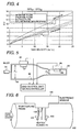
- the calculated value ⁇ u as a function of gas velocity may be graphed as illustrated in FIG. 4. From FIG. 4, it can therefore be seen that the quantity ⁇ u, as well as the slope of the graph ⁇ u, varies as a function of different gas types.
- the microprocessor based processing means 44 utilizing lookup tables stored in memory 45 (FIG. 3), mapping, or mathematical equations, then determines the type of gas as a function of both ⁇ u and the slope of ⁇ u.
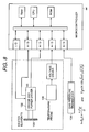
- a first hot element mass flow transducer 80 has its hot element 82 positioned within the conduit 84 in contact with the gas between the source 32 and outlet 34.
- a second heated element mass flow sensor 86 has its heated element 88 positioned in the conduit 84 in contact with the gas but in a portion of the conduit 84 having a different bore size than the portion of the conduit 84 in which the heated element 82 of the first sensor 80 is positioned.
- Both sensors 80 and 86 are calibrated for the same gas, e.g. methane, and both provide electrical output signals to the processing means 44.
- the output signals V o from the sensor 80 and V o ' from the second sensor 86 are proportional to the mass flow rate or gas velocity through the conduit 84.
- a temperature sensor 90 also provides an electrical output signal to the processing means 44 representative of the temperature of the ambient gas flowing through the conduit 84.
- V o 24.123* A * C 1 + C 2 u 0.35 1 + B u 1 : velocity in bore 1
- V ' o 24.123* A * C 1 + C 2 u 0.35 2 + B u 2 : velocity in bore 2
- V o is the output from sensor 80 while V o ' is the output from the sensor 86.
- the processing means 44 by utilizing mapping, lookup tables, or mathematical equations as well as the output from the temperature sensor 90 then estimates the gas type as a function of the value of ⁇ u and its slope.
- FIG. 6 a still further embodiment of the present invention is there shown in which a single gas flow sensor 100 is mounted to the conduit 102 through which the gas flows.
- the flow sensor 100 utilizes two heated elements 104 and 106 as well as an ambient temperature sensor 108.
- Each heated element 104 and 106 furthermore, includes its own circuitry, like the type illustrated in FIG. 1, except that the heated elements 104 and 106 each have internal temperature compensation and trim for a specific and different type of gas.
- the circuitry driving the heated element 104 may be trimmed and calibrated for methane while the heated element 106 may be calibrated and trimmed for a different gas, such as propane.
- the third embodiment of the invention illustrated in FIG. 6 is thus essentially identical to the first embodiment of the invention illustrated in FIG. 3 except that instead of using two separate sensors 40 and 50 (FIG. 1), each calibrated for a different gas, the third embodiment of the invention utilizes a single sensor 100 having two discrete heated elements 104 and 106.
- the calculations and method for determining the type of gas for the third embodiment of the invention is substantially identical to the first embodiment of the invention and, for that reason, is incorporated by reference.
- FIG. 7 a fourth embodiment of the present invention is there shown diagrammatically in which two different heated elements 110 and 112 are both disposed within the gas flow of the system.
- Each heated element 110 and 112 has its associated bridge and power driver 114 and 116, respectively, such that the outputs V o and V o ' from the drivers 114 and 116, respectively, are proportional to the gas mass flow rate across the heated elements 110 and 112.
- These output signals V o and V o ' are coupled as input signals to the microprocessor based processing means 44.
- a temperature probe in contact with the gas in the system provides an electrical output signal proportional to the temperature of the ambient gas within the system.
- the output from the temperature probe 118 is also coupled as an input signal to the processing means 44.
- the ⁇ T between the ambient air and the temperature of heated element was maintained at a constant 200°C as is conventional.
- the ⁇ T between the ambient temperature and the first heated element 110 is maintained at a first difference, for example 200°C.
- the ⁇ T between the ambient temperature and the. second heated element 112 is maintained at a different amount, for example 160°C.
- the system includes a heated element 120 which is powered through a bridge and power driver 122.
- the bridge and power driver 122 provides an output signal V o to the processing means 44 as in the previously described fashion.
- a temperature probe 126 also provides an electrical output signal as an input signal to the processing means 44 representative of the ambient temperature of the gas.
- a pressure transducer 128 is also in contact with the gas. in the system and generates an electrical output signal to the processing means 44 representative of the gas pressure.
- the thermal conductivity changes as well.
- the gas pressure transducer 128 is required. As the pressure, and thus the density, of the gas increases, the losses from the hot element 120 to the gas increase so that the output voltage will likewise increase.
- a processing means 44 by utilizing lookup tables, mapping or mathematical equations, is then able to determine the gas type by solving the above-identified simplification of King's law.
- the temperature difference between the heated element 120 and the ambient air may be varied to obtain multiple data points. A slope is then calculated between those different points and the gas type is determined based upon that slope. Such lookup tables may be based upon either experimental or simulated values.
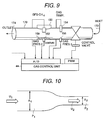
- a sixth embodiment of the present invention is there shown utilizing a hot element flow sensor 150, a temperature sensor 154 and two gas pressure sensors 152 and 156. All of the sensors 150, 152, 154 and 156 are disposed in a conduit 170 fluidly connected in series between the gas source 172 and outlet 174 and thus in contact with the gas flow. Each of these sensors 150-156 produce electrical output signals representative of their measured gas condition as input signals to the microprocessor based processing means 44.
- the mass flow sensors 150 and pressure 152 are both disposed within a venturi 158 in the conduit 170 while the gas pressure sensor 156 is positioned upstream from the venturi 158.
- u 2 A 1 A 2 u 1
- the error between the two detection methods can be evaluated and a compensation factor and gas type can be derived by lookup table or other dynamic method.
- the present invention provides a novel system and method for detecting the type of gas in a gaseous system using two or more sensors, each of which generate output signals representative of a condition of the gas.
- the hot element mass flow sensor may be calibrated or trimmed in accordance with the then identified gas type.
Landscapes
- Chemical & Material Sciences (AREA)
- Health & Medical Sciences (AREA)
- Engineering & Computer Science (AREA)
- Life Sciences & Earth Sciences (AREA)
- Analytical Chemistry (AREA)
- General Physics & Mathematics (AREA)
- General Chemical & Material Sciences (AREA)
- Food Science & Technology (AREA)
- Medicinal Chemistry (AREA)
- Physics & Mathematics (AREA)
- Chemical Kinetics & Catalysis (AREA)
- Biochemistry (AREA)
- General Health & Medical Sciences (AREA)
- Oil, Petroleum & Natural Gas (AREA)
- Immunology (AREA)
- Pathology (AREA)
- Measuring Volume Flow (AREA)
- Details Of Flowmeters (AREA)
- Investigating Or Analyzing Materials By The Use Of Electric Means (AREA)
- Investigating Or Analyzing Materials Using Thermal Means (AREA)
- Investigating Or Analyzing Materials By The Use Of Fluid Adsorption Or Reactions (AREA)
Abstract
Description
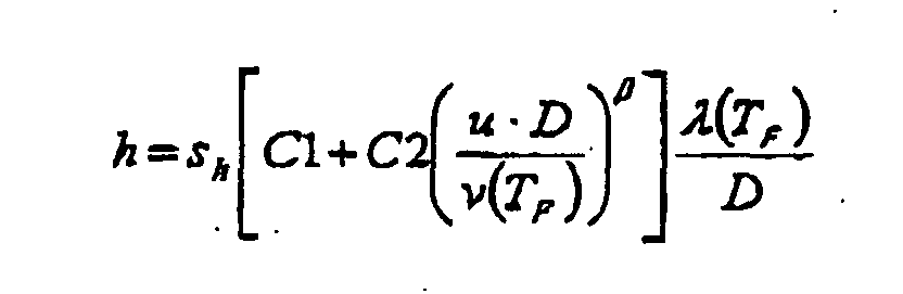
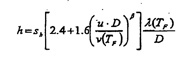
- C1 and C2:
- Constants
- sh:
- Surface area of the hot wire (π·D·L)
- u:
- Gas velocity [m/s]
- D:
- Hot wire diameter [m]
- v(TF):
- Kinematic viscosity [m2/s]
- λ(TF):
- Thermal conductivity [W/m·K]
- TF:
- Hot wire surface (film) temperature [K]
- L:
- Hot wire length [m]
- β:
- Empirically determined constant
- P =
- power,
- h =
- transfer coefficient from King's law, and
- ΔT =
- temperature difference between the hot element and the ambient air (conventionally 200° centigrade).

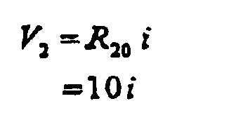
- R20 =
- resistance of resistor 20 = 10 ohms
- i =
- current through hot element.
- V1 =
- first voltage output from sensor 40 at a first air velocity
- V2 =
- voltage output from sensor 40 at a second air velocity
- V1' =
- voltage output from the second sensor 50 at the first gas velocity
- V2' =
- voltage output from the second sensor 50 at the second gas velocity
- u1 =
- gas flow rate from the first sensor 40,
- u2 =
- gas flow rate from the sensor 50, and
- Δu =
- the difference between the mass flow rate u1 and u2 at a given time.
Which simplifies to
- Q
- is the mass flow rate,
- u
- is the mass flow velocity,
- P1
- is the pressure at the pressure transducer 156,
- P2
- is the pressure at the pressure transducer 152, and
- TG
- is the gas temperature determined by temperature sensor 154.
Claims (19)
- A system for identifying a type of gas comprising:wherein each of said first and second conditions of the gas are selected from the group of temperature, mass flow rate, temperature and pressure.a first sensor in contact with the gas, said first sensor providing a first electrical output signal indicative of a first condition of the gas,a second sensor in contact with the gas, said second sensor providing a second electrical output signal indicative of a second condition of the gas,processing means (44) which receives said first and second output signals as input signals for determining the type of gas,
- The invention as defined in claim 1 wherein said first sensor comprises a non-linear mass flow sensor (40) having preset temperature compensation for a first predetermined gas type and said second sensor comprises a non-linear mass flow sensor (50) having preset temperature compensation for a second predetermined gas type, said first and second predetermined gas types being different from each other.
- The invention as defined in claim 1 wherein said first sensor comprises a mass flow sensor (80) positioned in a first bore of a first cross sectional area, said second sensor comprises a mass flow sensor (86) positioned in a second bore of a second cross sectional area different than said first cross sectional area, said first and second bores being fluidly connected in series with each other.
- The invention as defined in claim 3 wherein said first and second sensors (80, 86) each comprise a non-linear mass flow sensor having preset temperature compensation for a predetermined gas type.
- The invention as defined in claim 4 wherein both said first and second sensors (80, 86) have said preset temperature compensation for the same gas type, and comprising a temperature sensor (90) in contact with the gas, said temperature sensor (90) producing an electrical output signal proportional to the gas temperature, said temperature sensor output signal being coupled as an input signal to said processing means (44).
- The invention as defined in claim 2 wherein said first and said second flow sensors (40, 50) comprise a hot element mass flow sensor (100), said hot element for said flow sensors being mounted in a common housing.
- The invention as defined in claim 1 wherein said first sensor comprises a flow sensor having a heated element and said second sensor comprises a temperature sensor which measures the temperature of the gas, means for varying the temperature differential between said heated element and said gas temperature at a constant mass flow rate through said flow sensor.
- The invention as defined in claim 1 wherein said first sensor comprises a flow sensor having a heated element (110) and said second sensor comprises a temperature sensor (118) which measures the temperature of the gas, a second flow sensor having a heated element (112), means for maintaining a first temperature differential between said heated element of said first sensor, and means for maintaining a second temperature differential between said heated element of said second flow sensor, said first and second temperature differentials being different from each other.
- The invention as defined in claim 1 wherein said first sensor comprises a flow sensor having a heated element (120) and wherein said second sensor comprises a pressure sensor (128).
- The invention as defined in claim 9 and comprising a temperature sensor which produces an output signal representative of the temperature of the gas, and means for varying the temperature differential between said heated element and the gas temperature.
- The invention as defined in claim 1 wherein said first sensor comprises a mass flow sensor (150), said second sensor comprises a pressure sensor (152) positioned in a bore of a first predetermined cross sectional area in series with said mass flow sensor, and a second pressure sensor (156) positioned in a bore of a second predetermined cross sectional area in series with said first bore, said second pressure sensor providing an output signal to said processing means representative of the gas pressure.
- The invention as defined in claim 1 wherein said processing means comprises a microprocessor having accessible electronic memory, and at least one lookup table stored in said electronic memory.
- A method for determining the type of gas in a volume of gas comprising the steps of:wherein said first and second conditions of the gas are each selected from the group of temperature, mass flow rate, temperature and pressure.measuring a first condition of the gas in the gas volume with a first sensor in contact with the gas, said first sensor providing a first electrical output signal representative of said first condition,measuring a second condition of the gas in the gas volume with a second sensor in contact with the gas, said second sensor providing a first electrical output signal representative of said second condition, andprocessing said outputs from said first and second sensors to determine the gas type by comparing said sensor outputs with predetermined values,
- The invention as defined in claim 13 wherein said first and second conditions each comprise mass flow rate of the gas.
- The invention as defined in claim 14 and comprising the further step of measuring the temperature of the gas and utilizing the gas temperature as a variable factor in said processing step.
- The invention as defined in claim 13 wherein one of said conditions comprises the pressure of the gas.
- The invention as defined in claim 13 wherein one of said conditions comprises the temperature of the gas.
- The invention as defined in claim 13 wherein said processing step comprises the step of comparing said outputs from said sensors to predetermined tables stored in electronic memory.
- A system for identifying a type of gas in a gaseous fuel automotive internal combustion engine comprising:wherein each of said first and second conditions of the gas are selected from the group of temperature, mass flow rate, temperature and pressure.a first sensor in contact with the gas, said first sensor providing a first electrical output signal indicative of a first condition of the gas,a second sensor in contact with the gas, said second sensor providing a second electrical output signal indicative of a second condition of the gas,processing means which receives said first and second output signals as input signals for determining the type of gas,
Applications Claiming Priority (2)
| Application Number | Priority Date | Filing Date | Title |
|---|---|---|---|
| US51318 | 2002-01-18 | ||
| US10/051,318 US6640626B2 (en) | 2002-01-18 | 2002-01-18 | Method and system for identifying a type of gas |
Publications (3)
| Publication Number | Publication Date |
|---|---|
| EP1329715A2 true EP1329715A2 (en) | 2003-07-23 |
| EP1329715A3 EP1329715A3 (en) | 2004-03-17 |
| EP1329715B1 EP1329715B1 (en) | 2006-07-19 |
Family
ID=21970554
Family Applications (1)
| Application Number | Title | Priority Date | Filing Date |
|---|---|---|---|
| EP03000692A Expired - Lifetime EP1329715B1 (en) | 2002-01-18 | 2003-01-17 | Method and system for identifying gas type |
Country Status (5)
| Country | Link |
|---|---|
| US (1) | US6640626B2 (en) |
| EP (1) | EP1329715B1 (en) |
| JP (1) | JP2003262596A (en) |
| CN (1) | CN1495424A (en) |
| DE (1) | DE60306819T2 (en) |
Cited By (2)
| Publication number | Priority date | Publication date | Assignee | Title |
|---|---|---|---|---|
| EP2189764A1 (en) * | 2008-11-19 | 2010-05-26 | Endress + Hauser Flowtec AG | Method and measuring system for determining and/or monitoring a phase change of a measuring medium in a thermal flow meter |
| US9354220B2 (en) | 2013-09-27 | 2016-05-31 | Caterpillar Inc. | Engine system having fuel quality sensor |
Families Citing this family (36)
| Publication number | Priority date | Publication date | Assignee | Title |
|---|---|---|---|---|
| AU2003239621A1 (en) * | 2002-05-24 | 2003-12-12 | Mykrolis Corporation | System and method for mass flow detection device calibration |
| US6829930B2 (en) * | 2002-05-29 | 2004-12-14 | Degree Controls, Inc. | Gas velocity and temperature sensor system |
| US6712084B2 (en) | 2002-06-24 | 2004-03-30 | Mks Instruments, Inc. | Apparatus and method for pressure fluctuation insensitive mass flow control |
| US7809473B2 (en) * | 2002-06-24 | 2010-10-05 | Mks Instruments, Inc. | Apparatus and method for pressure fluctuation insensitive mass flow control |
| US7136767B2 (en) * | 2002-06-24 | 2006-11-14 | Mks Instruments, Inc. | Apparatus and method for calibration of mass flow controller |
| US7654128B2 (en) * | 2005-12-23 | 2010-02-02 | Ford Motor Company | Gas analyzing apparatus and method |
| JP4933192B2 (en) * | 2006-08-09 | 2012-05-16 | キヤノン株式会社 | Combustible gas detector and fuel cell system equipped with combustible gas detector |
| US7895890B2 (en) * | 2007-07-03 | 2011-03-01 | Van Ee William J | Liquid depth sensing and identification system |
| JP5511470B2 (en) * | 2010-03-30 | 2014-06-04 | アズビル株式会社 | Thermal flow meter, thermal gas type discrimination device, and automatic gas type judgment method |
| US20120036925A1 (en) * | 2010-08-10 | 2012-02-16 | Sentry Equipment Corporation | Digital Flow Meter with Enhanced Turndown Ratio |
| DE102010043686A1 (en) | 2010-11-10 | 2012-05-10 | Agilent Technologies Inc. | Determining a liquid composition from differently obtained flow signals |
| EP2677283A4 (en) * | 2011-02-18 | 2015-05-20 | Tohoku Gakuin | Heat conduction-type sensor having influence of temperature and kind of fluid corrected therein, and heat-type flow sensor and heat-type barometric sensor using the heat conduction-type sensor |
| US9506888B2 (en) | 2011-04-13 | 2016-11-29 | 3M Innovative Properties Company | Vapor sensor including sensor element with integral heating |
| WO2012141925A1 (en) | 2011-04-13 | 2012-10-18 | 3M Innovative Properties Company | Method of detecting volatile organic compounds |
| US9279792B2 (en) | 2011-04-13 | 2016-03-08 | 3M Innovative Properties Company | Method of using an absorptive sensor element |
| US8746158B2 (en) * | 2011-09-09 | 2014-06-10 | Cnh Industrial Canada, Ltd. | System and method for measuring product flow to an agricultural implement |
| JP6038950B2 (en) | 2011-12-13 | 2016-12-07 | スリーエム イノベイティブ プロパティズ カンパニー | Method for identification and quantitative measurement of unknown organic compounds in gaseous media |
| JP5874613B2 (en) * | 2012-11-22 | 2016-03-02 | 株式会社島津製作所 | Predetermined room gas displacement device for analysis or measurement |
| US9121773B2 (en) | 2013-03-13 | 2015-09-01 | Bascom-Turner Instruments | Gas sensors and methods of calibrating same |
| SI24577A (en) * | 2013-12-13 | 2015-06-30 | Univerza v Ljubljani, Fakulteta za strojništvo - LMPS | Thermal mass flow meter and the gas-identification method |
| US10302609B2 (en) | 2014-02-07 | 2019-05-28 | Detector Electronics Corporation | Calibration for gas detection |
| CN104216425B (en) * | 2014-08-29 | 2017-07-25 | 湖南三德科技股份有限公司 | Carrier gas type automatic identifying method and electronic flow controller for electronic flow controller |
| JP6534849B2 (en) * | 2015-04-01 | 2019-06-26 | 日本特殊陶業株式会社 | Fluid condition detection device |
| CN105181005B (en) * | 2015-04-24 | 2017-10-20 | 西安交通大学 | The integral measurement method and device of gas flow and concentration of component |
| WO2017196293A1 (en) * | 2016-05-09 | 2017-11-16 | Cummins Inc. | Fuel type prediction from mass flow measurements and thermal conductivity sensor |
| DE102016117215A1 (en) * | 2016-09-13 | 2018-03-15 | Bundesrepublik Deutschland, Vertreten Durch Das Bundesministerium Für Wirtschaft Und Energie, Dieses Vertreten Durch Den Präsidenten Der Physikalisch-Technischen Bundesanstalt | A method of determining a composition of a gaseous fluid and gas composition sensor |
| WO2018135100A1 (en) * | 2017-01-19 | 2018-07-26 | Tdk株式会社 | Gas sensor |
| US10942157B2 (en) | 2018-02-21 | 2021-03-09 | Stmicroelectronics Pte Ltd | Gas sensor device for detecting gases with large molecules |
| JP2019178899A (en) * | 2018-03-30 | 2019-10-17 | アズビル株式会社 | Thermal flowmeter and flow rate correction method |
| JP2019183801A (en) * | 2018-04-16 | 2019-10-24 | いすゞ自動車株式会社 | Internal combustion engine and method for controlling internal combustion engine |
| JP7248455B2 (en) * | 2019-03-04 | 2023-03-29 | アズビル株式会社 | Thermal flow meter and flow correction method |
| US12369558B2 (en) | 2019-03-15 | 2025-07-29 | TZero Research & Development LLC | System for monitoring and displaying status of processing a dairy product |
| US12127527B2 (en) | 2019-03-15 | 2024-10-29 | TZero Research & Development LLC | System for monitoring and displaying status of processing a dairy product |
| US11326996B2 (en) | 2019-03-15 | 2022-05-10 | TZero Research & Development LLC | System for monitoring and displaying status of processing of a fluid |
| US11300535B2 (en) * | 2019-04-05 | 2022-04-12 | Honeywell International Inc. | Integrated sensor apparatus with pressure sensing element and flow sensing element |
| US11874028B2 (en) * | 2021-03-22 | 2024-01-16 | Rheem Manufacturing Company | Modulating gas orifice |
Family Cites Families (10)
| Publication number | Priority date | Publication date | Assignee | Title |
|---|---|---|---|---|
| US4163390A (en) * | 1977-04-14 | 1979-08-07 | Rodder Jerome A | Bipolar fluid measuring apparatus |
| JPS5826221A (en) * | 1981-08-10 | 1983-02-16 | Hitachi Ltd | Measuring device for flow rate of air in internal-combustion engine |
| US4542640A (en) * | 1983-09-15 | 1985-09-24 | Clifford Paul K | Selective gas detection and measurement system |
| GB8702390D0 (en) * | 1987-02-03 | 1987-03-11 | Warwick University Of | Identifying/measuring odorants |
| US5099697A (en) * | 1990-04-02 | 1992-03-31 | Agar Corporation Ltd. | Two and three-phase flow measurement |
| AU3055992A (en) * | 1991-10-23 | 1993-05-21 | Niagara Mohawk Power Corporation | On-line combustionless measurement of gaseous fuels fed to gas consumption devices |
| EP0554095A3 (en) * | 1992-01-30 | 1994-12-14 | Honeywell Inc | Determination of fuel characteristics |
| US5415024A (en) * | 1992-12-16 | 1995-05-16 | Marathon Oil Company | Composition analyzer for determining composition of multiphase multicomponent fluid mixture |
| CA2236615C (en) * | 1998-04-30 | 2006-12-12 | Konstandinos S. Zamfes | Differential total-gas determination while drilling |
| GB9909217D0 (en) * | 1999-04-22 | 1999-06-16 | British Gas Plc | Measurement of fluid concentrations |
-
2002
- 2002-01-18 US US10/051,318 patent/US6640626B2/en not_active Expired - Fee Related
-
2003
- 2003-01-08 JP JP2003001629A patent/JP2003262596A/en active Pending
- 2003-01-17 DE DE60306819T patent/DE60306819T2/en not_active Expired - Fee Related
- 2003-01-17 EP EP03000692A patent/EP1329715B1/en not_active Expired - Lifetime
- 2003-01-17 CN CNA031017126A patent/CN1495424A/en active Pending
Cited By (3)
| Publication number | Priority date | Publication date | Assignee | Title |
|---|---|---|---|---|
| EP2189764A1 (en) * | 2008-11-19 | 2010-05-26 | Endress + Hauser Flowtec AG | Method and measuring system for determining and/or monitoring a phase change of a measuring medium in a thermal flow meter |
| US8191418B2 (en) | 2008-11-19 | 2012-06-05 | Endress + Hauser Flowtec Ag | Method and measuring system for determining and/or monitoring an aggregate state change of a measured medium on a thermal, flow measuring device |
| US9354220B2 (en) | 2013-09-27 | 2016-05-31 | Caterpillar Inc. | Engine system having fuel quality sensor |
Also Published As
| Publication number | Publication date |
|---|---|
| CN1495424A (en) | 2004-05-12 |
| DE60306819D1 (en) | 2006-08-31 |
| US20030136175A1 (en) | 2003-07-24 |
| US6640626B2 (en) | 2003-11-04 |
| JP2003262596A (en) | 2003-09-19 |
| EP1329715B1 (en) | 2006-07-19 |
| EP1329715A3 (en) | 2004-03-17 |
| DE60306819T2 (en) | 2007-02-08 |
Similar Documents
| Publication | Publication Date | Title |
|---|---|---|
| EP1329715A2 (en) | Method and system for identifying gas type | |
| US5535614A (en) | Thermal conductivity gas sensor for measuring fuel vapor content | |
| US4283944A (en) | Apparatus for measuring the mass of a fluid medium | |
| EP0152942A2 (en) | Device for detecting air-fuel ratio of mixture over wide range from below to above stoichiometric ratio | |
| EP0387025B1 (en) | Temperature compensating circuit | |
| JPH03237353A (en) | Electrostatic capacity type alcohol concentration measuring instrument | |
| US4502325A (en) | Measurement of mass airflow into an engine | |
| US20040211253A1 (en) | Thermal type flow measuring device | |
| US5419187A (en) | Air flow rate meter and detection method | |
| JPH05209551A (en) | Inspection of function of electric car heater and its device | |
| US8844350B2 (en) | Flow quantity measuring apparatus including branched conductive lines connected to midpoints of series circuits of the bridge circuit | |
| EP0172440B1 (en) | Hot-wire flow rate measuring apparatus | |
| US4534218A (en) | Thermal flow meter | |
| US6862930B1 (en) | Fluid flow amount measuring apparatus responsive to fluid flow in forward and reverse directions | |
| US6981411B2 (en) | Measuring element for a flow rate sensor, in particular an air-mass flowsensor for internal combustion engines | |
| US7493802B2 (en) | Liquid type identification device | |
| EP1657532A1 (en) | Thermal mass flow sensor | |
| US4384484A (en) | Gas flow measuring device | |
| EP0890827A1 (en) | Thermal type flow measuring instrument and temperature-error correcting apparatus thereof | |
| EP1742025B1 (en) | Thermal type flow measuring apparatus | |
| US5394746A (en) | Hot wire flow rate measuring circuit | |
| US4261199A (en) | Air flow measurement apparatus | |
| US5656938A (en) | Temperature compensation in mass flow sensors employing the hot-wire anemometer principle | |
| JP2003302271A (en) | Flow measurement unit package and flow measurement unit using the same | |
| US20110107826A1 (en) | Apparatus and method for mass air measuring |
Legal Events
| Date | Code | Title | Description |
|---|---|---|---|
| PUAI | Public reference made under article 153(3) epc to a published international application that has entered the european phase |
Free format text: ORIGINAL CODE: 0009012 |
|
| AK | Designated contracting states |
Designated state(s): AT BE BG CH CY CZ DE DK EE ES FI FR GB GR HU IE IT LI LU MC NL PT SE SI SK TR |
|
| AX | Request for extension of the european patent |
Extension state: AL LT LV MK RO |
|
| PUAL | Search report despatched |
Free format text: ORIGINAL CODE: 0009013 |
|
| AK | Designated contracting states |
Kind code of ref document: A3 Designated state(s): AT BE BG CH CY CZ DE DK EE ES FI FR GB GR HU IE IT LI LU MC NL PT SE SI SK TR |
|
| AX | Request for extension of the european patent |
Extension state: AL LT LV MK RO |
|
| RIC1 | Information provided on ipc code assigned before grant |
Ipc: 7G 01N 33/00 A Ipc: 7G 01N 33/22 B Ipc: 7F 02D 35/00 B Ipc: 7G 01N 25/20 B |
|
| 17P | Request for examination filed |
Effective date: 20040708 |
|
| 17Q | First examination report despatched |
Effective date: 20041020 |
|
| AKX | Designation fees paid |
Designated state(s): DE IT |
|
| GRAP | Despatch of communication of intention to grant a patent |
Free format text: ORIGINAL CODE: EPIDOSNIGR1 |
|
| GRAC | Information related to communication of intention to grant a patent modified |
Free format text: ORIGINAL CODE: EPIDOSCIGR1 |
|
| GRAS | Grant fee paid |
Free format text: ORIGINAL CODE: EPIDOSNIGR3 |
|
| GRAA | (expected) grant |
Free format text: ORIGINAL CODE: 0009210 |
|
| RAP1 | Party data changed (applicant data changed or rights of an application transferred) |
Owner name: HITACHI, LTD. |
|
| AK | Designated contracting states |
Kind code of ref document: B1 Designated state(s): DE IT |
|
| PG25 | Lapsed in a contracting state [announced via postgrant information from national office to epo] |
Ref country code: IT Free format text: LAPSE BECAUSE OF FAILURE TO SUBMIT A TRANSLATION OF THE DESCRIPTION OR TO PAY THE FEE WITHIN THE PRESCRIBED TIME-LIMIT;WARNING: LAPSES OF ITALIAN PATENTS WITH EFFECTIVE DATE BEFORE 2007 MAY HAVE OCCURRED AT ANY TIME BEFORE 2007. THE CORRECT EFFECTIVE DATE MAY BE DIFFERENT FROM THE ONE RECORDED. Effective date: 20060719 |
|
| REF | Corresponds to: |
Ref document number: 60306819 Country of ref document: DE Date of ref document: 20060831 Kind code of ref document: P |
|
| PLBE | No opposition filed within time limit |
Free format text: ORIGINAL CODE: 0009261 |
|
| STAA | Information on the status of an ep patent application or granted ep patent |
Free format text: STATUS: NO OPPOSITION FILED WITHIN TIME LIMIT |
|
| 26N | No opposition filed |
Effective date: 20070420 |
|
| PGFP | Annual fee paid to national office [announced via postgrant information from national office to epo] |
Ref country code: DE Payment date: 20090219 Year of fee payment: 7 |
|
| PGFP | Annual fee paid to national office [announced via postgrant information from national office to epo] |
Ref country code: IT Payment date: 20090128 Year of fee payment: 7 |
|
| PG25 | Lapsed in a contracting state [announced via postgrant information from national office to epo] |
Ref country code: DE Free format text: LAPSE BECAUSE OF NON-PAYMENT OF DUE FEES Effective date: 20100803 |
|
| PG25 | Lapsed in a contracting state [announced via postgrant information from national office to epo] |
Ref country code: IT Free format text: LAPSE BECAUSE OF NON-PAYMENT OF DUE FEES Effective date: 20100117 |